Table of Contents
Advertisement
Quick Links
Advertisement
Table of Contents

Related Manuals for Asus M5A99FX PRO R2.0


Summary of Contents for Asus M5A99FX PRO R2.0
- Page 1 M5A99FX PRO R2.0...
- Page 2 Product warranty or service will not be extended if: (1) the product is repaired, modified or altered, unless such repair, modification of alteration is authorized in writing by ASUS; or (2) the serial number of the product is defaced or missing.
-
Page 3: Table Of Contents
Contents Safety information ... vi About this guide ... vii M5A99FX PRO R2.0 specifications summary ... ix Package contents ... xiii Installation tools and components ... xiv Chapter 1: Product introduction Special features... 1-1 1.1.1 Product highlights... 1-1 1.1.2 Dual Intelligent Processors 3 with New DIGI+ Power Control ... 1-2 1.1.3... - Page 4 CPU Core On/Off Function ... 3-23 Onboard Devices Configuration ... 3-23 APM ... 3-25 Network Stack ... 3-26 ASUS EZ Flash 2 Utility ... 3-32 ASUS SPD Information ... 3-32 ASUS O.C. Profile ... 3-33 ASUS Update ... 3-35 ASUS EZ Flash 2 ... 3-38 ASUS BIOS Updater ...
- Page 5 Installing two SLI-ready graphics cards ... 6-5 6.2.3 Installing the device drivers ... 6-6 6.2.4 Enabling the NVIDIA Appendices Notices ... A-1 ASUS contact information ... A-4 ... 5-6 ® OS installation ... 5-7 ® CrossFireX™ technology ... 6-3 ®...
-
Page 6: Electrical Safety
Safety information Electrical safety • To prevent electrical shock hazard, disconnect the power cable from the electrical outlet before relocating the system. • When adding or removing devices to or from the system, ensure that the power cables for the devices are unplugged before the signal cables are connected. If possible, disconnect all power cables from the existing system before you add a device. -
Page 7: About This Guide
Refer to the following sources for additional information and for product and software updates. ASUS websites The ASUS website provides updated information on ASUS hardware and software products. Refer to the ASUS contact information. Optional documentation Your product package may include optional documentation, such as warranty flyers, that may have been added by your dealer. -
Page 8: Conventions Used In This Guide
Conventions used in this guide To ensure that you perform certain tasks properly, take note of the following symbols used throughout this manual. DANGER/WARNING: Information to prevent injury to yourself when trying to complete a task. CAUTION: Information to prevent damage to the components when trying to complete a task IMPORTANT: Instructions that you MUST follow to complete a task. -
Page 9: M5A99Fx Pro R2.0 Specifications Summary
Dual channel memory architecture * Due to CPU spec., AMD 100 Series CPUs support up to DDR3 1066MHz. With ASUS design, this motherboard can support up to DDR3 1333MHz. ** Due to OS limitation, when installing total memory of 4GB capacity or more, Windows®... - Page 10 ASUS EPU - EPU ASUS TPU - Auto Tuning, TurboV ASUS Exclusive Features - ASUS UEFI BIOS EZ Mode featuring friendly graphics user interface - Remote GO! - Front Panel USB 3.0 Support - Network iControl - USB 3.0 Boost...
- Page 11 M5A99FX PRO R2.0 specifications summary ASUS overclocking features Back Panel I/O Ports Internal I/O Ports Precision Tweaker 2: - vCore: Adjustable CPU voltage at 0.00625V increment - vDDNB: Adjustable CPU/NB voltage at 0.00625V increment - vNB: Adjustable NB voltage at 0.00625V increment - vNB HT bus: Adjustable HT voltage at 0.00625V increment...
- Page 12 Specifications are subject to change without notice. 64 Mb Flash ROM, UEFI BIOS, PnP, DMI2.0, WfM2.0, SM BIOS 2.7, ACPI 2.0a, Multi-language BIOS, ASUS EZ Flash 2, F12 PrintScreen, F3 Shortcut Function and ASUS DRAM SPD (Serial Presence Detect) memory information WfM 2.0, DMI 2.0, WOL by PME, WOR by PME, PXE...
-
Page 13: Package Contents
Check your motherboard package for the following items. ASUS M5A99FX PRO R2.0 motherboard 4 x Serial ATA 6.0 Gb/s cables 1 x ASUS SLI™ bridge connector • If any of the above items is damaged or missing, contact your retailer. •... -
Page 14: Installation Tools And Components
Installation tools and components 1 bag of screws Philips (cross) screwdriver PC chassis Power supply unit AMD AM3+ CPU AMD AM3+ compatible CPU Fan DIMM SATA hard disk drive SATA optical disc drive (optional) Graphics card (optional) The tools and components in the table above are not included in the motherboard package. -
Page 15: Chapter 1: Product Introduction
PCI Express 2.0 interface. Complete USB 3.0 Integration ASUS facilitates strategic USB 3.0 accessibility for both the front and rear panel – 4 USB 3.0 ports in total. Experience the latest plug & play connectivity at speeds up to 10 times faster than USB 2.0. -
Page 16: Dual Intelligent Processors 3 With New Digi+ Power Control
TPU with the All-New SMART DIGI+ Key for a Blazing Performance Boost Always at the forefront of power design, ASUS propels you into the future standard of power management again by giving you a complete CPU, memory and new SMART DIGI+ Technology with profile tuning digital power solution, which works with the TPU to ramp up performance to its maximum. -
Page 17: Asus Exclusive Features
ASUS Fan Xpert ASUS Fan Xpert intelligently allows you to adjust both the CPU and chassis fan speeds according to different ambient temperatures caused by different climate conditions in different geographic regions and your PC’s loading. The built-in variety of useful profiles offer flexible controls of fan speed to achieve a quiet and cool environment. -
Page 18: Asus Ez Diy
ASUS EZ-Flash 2 ASUS EZ Flash 2 is a user-friendly utility that allows you to update the BIOS without using a bootable floppy disk or an OS-based utility. Chapter 1: Product introduction... -
Page 19: Other Special Features
The motherboard is European Union’s Energy-related Products (ErP) ready, and ErP requires products to meet certain energy efficiency requirement in regards to energy consumptions. This is in line with ASUS vision of creating environment-friendly and energy-efficient products through product design and innovation to reduce carbon footprint of the product and thus mitigate environmental impacts. -
Page 20: Motherboard Overview
Motherboard overview 1.2.1 Before you proceed Take note of the following precautions before you install motherboard components or change any motherboard settings. • Unplug the power cord from the wall socket before touching any component. • Before handling components, use a grounded wrist strap or touch a safely grounded object or a metal object, such as the power supply case, to avoid damaging them due to static electricity. -
Page 21: Motherboard Layout
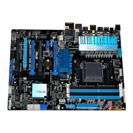
1.2.2 Motherboard layout Refer to 1.2.9 Internal connectors and 2.3.1 Rear I/O connection for more information about rear panel connectors and internal connectors. ASUS M5A99FX PRO R2.0... -
Page 22: Layout Contents
Layout contents Connectors/Jumpers/Slots 1. ATX power connectors (24-pin EATXPWR, 8-pin EATX12V) 2. AM3+/AM3 CPU Socket 3. CPU, CPU optional, and chassis fan connectors (4-pin CPU_FAN; CPU_OPT; CHA_FAN1/2/3) 4. DDR3 DIMM slots 5. MemOK! button 6. USB 3.0 connector (20-1 pin USB3_34) 7. -
Page 23: Central Processing Unit (Cpu)
Opteron processor. Ensure that you use a CPU designed for the AM3+ socket. The CPU fits in only one correct orientation. DO NOT force the CPU into the socket to prevent bending the connectors on the socket and damaging the CPU! ASUS M5A99FX PRO R2.0 ®... -
Page 24: System Memory
1.2.4 System memory The motherboard comes with four Double Data Rate 3 (DDR3) Dual Inline Memory Modules (DIMM) slots. A DDR3 module is notched differently from a DDR or DDR2 module. DO NOT install a DDR or DDR2 memory module to the DDR3 slot. Recommended memory configurations 1-10 Chapter 1: Product introduction... -
Page 25: Memory Configurations
• Due to the CPU spec., AMD AM3 100 series CPUs support up to DDR3 1066MHz. With ASUS design, this motherboard can support up to DDR3 1333MHz. • When overclocking, some AMD CPU models may not support DDR3 1600 or higher frequency DIMMs. - Page 26 M5A99FX PRO R2.0 Motherboard Qualified Vendors Lists (QVL) DDR3 2400(O.C.) MHz capability Vendors Part No. A-DATA AX3U2400GC4G10(XMP) G.SKILL F3-19200CL11Q- 16GBZHD(XMP) G.SKILL F3-19200CL11Q- 16GBZHD(XMP) G.SKILL F3-19200CL9Q- 16GBZMD(XMP) G.SKILL F3-19200CL10Q- 32GBZHD(XMP) G.SKILL F3-19200CL9D- 4GBPIS(XMP) GEIL GOC316GB2400 C10QC(XMP) GEIL GOC316GB2400 C11QC(XMP) Kingston KHX2400C11D3...
- Page 27 PV736G2000ELK(XMP) (3x2GB) Patriot PVT36G2000LLK(XMP) (3x2GB) Silicon SP002GBLYU200S02 Power (XMP) Team TXD32048M2000C9 (XMP) Team TXD32048M2000C9-L (XMP) Team TXD32048M2000C9-L (XMP) ASUS M5A99FX PRO R2.0 Chip Chip No. Timing Brand 9-11-9-27 9-9-9-27 10-10- 10-27 8-9-8-24 9-9-9-24 9-9-9-24 9-9-9-28 Hynix H5TQ2G83BF 9-9-9-27 RH9C 7-7-7-20...
- Page 28 DDR3 1866 MHz capability Vendors Part No. A-DATA AX3U1866GC2G9B(XMP) A-DATA AX3U1866GC4G9B(XMP) CORSAIR CMZ32GX3M4X1866 C10(Ver3.23)(XMP) CORSAIR CMZ8GX3M2A1866 C9(XMP) Crucial BLE4G3D1869DE1XT 0.16FMD(XMP) G.SKILL F3-14900CL9Q- 16GBXL(XMP) G.SKILL F3-14900CL9Q- 16GBZL(XMP) G.SKILL F3-14900CL10Q2- 64GBZLD(XMP) G.SKILL F3-14900CL9D- 8GBSR(XMP) G.SKILL F3-14900CL9Q- 8GBFLD(XMP) Patriot PXD34G1866ELK(XMP) Patriot PXD38G1866ELK(XMP) Patriot PXD38G1866ELK(XMP) Team TXD34096M1866HC9K-...
- Page 29 G.SKILL F3-12800CL9D-8GB SR2(XMP) (2x 4GB) G.SKILL F3-12800CL8D-8GB ECO(XMP) (2x4GB) GEIL GET316GB1600C9 16GB QC(XMP) (4x 4GB) GEIL GUP34GB1600C7DC(XMP) (2x 2GB) ASUS M5A99FX PRO R2.0 Chip Timing Chip NO. Brand A-DATA 3CCD- 1509A A-DATA 3CCD- 1509A 8-8-8-24 9-9-9-24 9-9-9-24 Heat-Sink Package 9-9-9-24...
- Page 30 DDR3 1600 MHz capability Vendors Part No. KINGMAX FLGE85F- C8KL9A(XMP) KINGSTON KHX1600C9D3K3/ 12GX(XMP) KINGSTON KHX1600C9D3T1BK3/ 12GX(XMP) KINGSTON KHX1600C9D3K3/ 12GX(XMP) KINGSTON KHX1600C9D3K6/ 24GX(XMP) Kingston KHX1600C9D3K8/ 32GX(XMP) KINGSTON KHX1600C9D3LK2/ 4GX(XMP) KINGSTON KHX1600C9D3X2K2/ 4GX(XMP) KINGSTON KHX1600C9D3K3/ 6GX(XMP) KINGSTON KHX1600C9D3K3/ 6GX(XMP) KINGSTON KHX1600C9D3T1K3/ 6GX(XMP) OCZ3BE1600C8LV4GK Transcend TS256MLK64V6N...
- Page 31 Silicon SP004GBLTU160V02(XMP) Power Team TXD31024M1600C8- D(XMP) Team TXD32048M1600C7- L(XMP) Team TXD32048M1600HC8- D(XMP) Team TED34096M1600HC11 Team TXD34096M1600HC9- D(XMP) ASUS M5A99FX PRO R2.0 Chip Chip No. Timing Brand GoodRam GF1008 K C-JN 6-8-6-24 6-8-6-24 23EY4587 MB6H 8-9-8-24 8-8-8-24 7-7-7-20 9-9-9-24 8-9-8-24 Hynix...
- Page 32 DDR3 1333 MHz capability Vendors Part No. A-DATA AD63I1B0823EV A-DATA AXDU1333GC2G9 (XMP) A-DATA AD63I1C1624EV A-DATA SU3U1333W8G9 (XMP) Apacer 78.A1GC6.9L1 Apacer 78.B1GDE.9L10C CORSAIR TW3X4G1333C9A CORSAIR CMX8GX3M2A1333 C9(XMP) G.SKILL F3-10600CL9D-4 GBNT G.SKILL F3-10666CL9D-8 GBRL G.SKILL F3-10666CL9D-8 GBRL G.SKILL F3-10666CL9D-8 GBXL GEIL GET316GB1333C GEIL GG34GB1333C9DC GEIL...
- Page 33 (574206) Transcend JM1333KLN-4G ( 583782 ) Transcend JM1333KLN-4G Transcend TS512MLK64V3N ( 585538 ) Transcend TS512MLK64V3N (574831) Transcend TS1GLK64V3H ASUS M5A99FX PRO R2.0 Chip Brand Chip No. Timing KINGMAX KFB8FNLXL- BN F-15A KINGMAX KFC8FNLBF-G XX-12A KINGMAX KFC8FNLXF-D XX-15A Micron IFD77 D9LGK...
- Page 34 DDR3 1333 MHz capability Vendors Part No. ACTICA ACT1GHU64B8F 1333S ACTICA ACT1GHU72C8G 1333S ACTICA ACT2GHU64B8G 1333M ACTICA ACT2GHU64B8G 1333S ACTICA ACT2GHU72D8G 1333M ACTICA ACT2GHU72D8G 1333S ACTICA ACT4GHU64B8H1 333H ACTICA ACT4GHU72D8H1 333H AQ56M72E8BJH9S AQ12M72E8BKH9S BUFFALO D3U1333-1G BUFFALO D3U1333-2G BUFFALO D3U1333-4G EK Memory EKM324L28BP8-I13 Elixir M2F2G64CB88B7...
- Page 35 (4) Supports four (4) modules inserted into both the blue and black slots as two pairs of Dual-channel memory configuration. • When overclocking, some AMD CPU models may not support DDR3 1600 or higher frequency DIMMS. • Visit the ASUS website for the latest QVL. ASUS M5A99FX PRO R2.0 Chip Brand Chip No. Timing 7-7-7-...
-
Page 36: Expansion Slots
1.2.5 Expansion slots Unplug the power cord before adding or removing expansion cards. Failure to do so may cause you physical injury and damage motherboard components. Slot No. Slot Description PCIe 2.0 x16_1 slot (dual at x16/x16 mode) PCIe 2.0 x1_1 slot PCIe 2.0 x16_2 slot [black] (at x4 mode, compatible with PCIe x1 and x4 devices) PCIe 2.0 x16_3 slot (dual at x16/x16 mode) -
Page 37: Irq Assignments For This Motherboard
– Realtek 8111F (LAN) – On Chip SATA – On Chip USB_1 – On Chip USB_2 – On Chip USB_3 – HD Audio shared ASUS M5A99FX PRO R2.0 – – – – – – – – – – – –... -
Page 38: Onboard Buttons And Switches
1.2.6 Onboard buttons and switches Onboard switches and buttons allow you to fine-tune performance when working on a bare or open-case system. This is ideal for overclockers and gamers who continually change settings to enhance system performance. Direct Key button (DirectKey) This feature allows your system to go to the BIOS Setup program with the press of a button. - Page 39 BIOS has been restored to its default settings. • We recommend that you download and update to the latest BIOS version from the ASUS website at www.asus.com after using the MemOK! function. ASUS M5A99FX PRO R2.0 1-25...
-
Page 40: Clear Rtc Ram
1.2.7 Jumpers Clear RTC RAM (3-pin CLRTC) This jumper allows you to clear the Real Time Clock (RTC) RAM in CMOS. You can clear the CMOS memory of date, time, and system setup parameters by erasing the CMOS RTC RAM data. The onboard button cell battery powers the RAM data in CMOS, which include system setup information such as system passwords. -
Page 41: Onboard Leds
The POST State LEDs provide the status of these key components during POST (Power-On-Self Test): CPU, memory modules, VGA card, and hard disk drive.s If an error is found, the critical component’s LED stays lit up until the problem is solved. ASUS M5A99FX PRO R2.0 1-27... -
Page 42: Internal Connectors
1.2.9 Internal connectors Serial ATA 6.0 Gb/s connectors (7-pin SATA6G_1-5 [gray]) ® These connectors are for the Serial ATA 6.0 Gb/s signal cables for Serial ATA hard disk drives and optical disc drives. If you installed Serial ATA hard disk drives, you can create a RAID 0, RAID 1, RAID 5, or RAID 10 configuration through the onboard AMD •... - Page 43 • When using NCQ, set the ASM1061 Storage Controller item in the BIOS to [Enabled]. Refer to section 3.5.6 Onboard Devices Configuration for details. ASUS M5A99FX PRO R2.0 XP Service Pack 3 or later versions before using Serial ATA ®...
- Page 44 USB 3.0 connector, you can have a front panel USB 3.0 solution. • You can connect the ASUS front panel USB 3.0 box to this connector to obtain the front panel USB 3.0 solution. •...
-
Page 45: Usb 2.0 Connectors
Never connect a 1394 cable to the USB connectors. Doing so will damage the motherboard! You can connect the front panel USB cable to the ASUS Q-Connector (USB, blue) first, and then install the Q-Connector (USB) to the USB connector onboard if your chassis supports front panel USB ports. - Page 46 Digital audio connector (4-1 pin SPDIF_OUT) This connector is for an additional Sony/Philips Digital Interface (S/PDIF) port. Connect the S/PDIF Out module cable to this connector, then install the module to a slot opening at the back of the system chassis. The S/PDIF module is purchased separately.
- Page 47 Only the CPU_FAN, CHA_FAN1, CHA_FAN2 and CHA_FAN3 connectors support the ASUS FAN Xpert feature. • If you install two VGA cards, we recommend that you plug the rear chassis fan cable to the motherboard connector labeled CHA_FAN1, CHA_FAN2 or CHA_FAN3 for better thermal environment. ASUS M5A99FX PRO R2.0 1-33...
- Page 48 Front panel audio connector (10-1 pin AAFP) This connector is for a chassis-mounted front panel audio I/O module that supports either HD Audio or legacy AC`97 audio standard. Connect one end of the front panel audio I/O module cable to this connector. •...
- Page 49 • If you are uncertain about the minimum power supply requirement for your system, refer to the Recommended Power Supply Wattage Calculator at http://support.asus. com/PowerSupplyCalculator/PSCalculator.aspx?SLanguage=en-us for details. • If you want to use two high-end PCI Express x16 cards, use a PSU with 1000W power or above to ensure the system stability.
-
Page 50: System Panel Connector
System panel connector (20-8 pin PANEL) This connector supports several chassis-mounted functions. • System power LED (2-pin PLED) This 2-pin connector is for the system power LED. Connect the chassis power LED cable to this connector. The system power LED lights up when you turn on the system power, and blinks when the system is in sleep mode. - Page 51 Connect the button cable that supports DirectKey, from the chassis to this connector on the motherboard. Ensure that your chassis comes with the button cable that supports the DirectKey feature. Refer to the technical documentation that came with the chassis for details. ASUS M5A99FX PRO R2.0 1-37...
- Page 52 Chapter 1: Product introduction 1-38...
-
Page 53: Chapter 2: Basic Installation
The diagrams in this section are for reference only. The motherboard layout may vary with models, but the installation steps are the same for all models. Install the ASUS I/O Shield to the chassis rear I/O panel. ASUS M5A99FX PRO R2.0... - Page 54 Place the motherboard into the chassis, ensuring that its rear I/O ports are aligned to the chassis’ rear I/O panel. Chapter 2: Getting started...
- Page 55 Place nine screws into the holes indicated by circles to secure the motherboard to the chassis. DO NOT overtighten the screws! Doing so can damage the motherboard. ASUS M5A99FX PRO R2.0...
-
Page 56: Cpu Installation
2.1.2 CPU installation The AMD AM3+ socket is compatible with AMD AM3+ and AM3 processors. Ensure you use a CPU designed for the AM3+ socket. The CPU fits in only one correct orientation. DO NOT force the CPU into the socket to prevent bending the connectors on the socket and damaging the CPU! Chapter 2: Getting started... -
Page 57: Cpu Heatsink And Fan Assembly Installation
2.1.3 CPU heatsink and fan assembly installation ASUS M5A99FX PRO R2.0 Apply the Thermal Interface Material to the CPU heatsink and CPU before you install the heatsink and fan if necessary. - Page 58 To install the CPU heatsink and fan assembly Chapter 2: Getting started...
- Page 59 ASUS M5A99FX PRO R2.0...
-
Page 60: Dimm Installation
2.1.4 DIMM installation To remove a DIMM Chapter 2: Getting started... -
Page 61: Atx Power Connection
2.1.5 ATX Power connection ASUS M5A99FX PRO R2.0... -
Page 62: Sata Device Connection
2.1.6 SATA device connection Chapter 2: Getting started 2-10... -
Page 63: Front I/O Connector
2.1.7 Front I/O Connector To install ASUS Q-Connector To install USB 2.0 connector USB 2.0 To install USB 3.0 connector USB 3.0 ASUS M5A99FX PRO R2.0 To install front panel audio connector AAFP 2-11... -
Page 64: Expansion Card Installation
2.1.8 Expansion Card installation To install PCIe x16 cards To install PCIe x1 cards To install PCI cards Chapter 2: Getting started 2-12... -
Page 65: Bios Update Utility
Flashback Wizard. Follow the onscreen instructions to complete the installation. You can also download the BIOS from the ASUS official website (www.asus.com). Rename the file as M5A99FX.CAP, save it to a USB portable device, and place it in the root directory. - Page 66 • Updating BIOS may have risks. If the BIOS program is damaged during the process and results to the system’s failure to boot up, please contact your local ASUS Service Center. 2-14...
-
Page 67: Motherboard Rear And Audio Connections
5. PS/2 keyboard port 6. Optical S/PDIF Out port *: Refer to the tables on the next page for LAN port LEDs, and audio port definitions. ASUS M5A99FX PRO R2.0 7. USB 2.0 ports 1 and 2 8. External SATA port 9. - Page 68 • Press the Clear CMOS switch to clear BIOS setup information only when the system hangs due to overclocking. • DO NOT insert a different connector to the external SATA port. • Due to USB 3.0 controller limitation, USB 3.0 devices can only be used under Windows ®...
-
Page 69: Audio I/O Connections
2.3.2 Audio I/O connections Audio I/O ports Connect to Headphone and Mic Connect to Stereo Speakers ASUS M5A99FX PRO R2.0 2-17... - Page 70 Connect to 2.1 channel Speakers Connect to 4.1 channel Speakers Connect to 5.1 channel Speakers Chapter 2: Getting started 2-18...
- Page 71 Connect to 7.1 channel Speakers When the DTS UltraPC II and DTS Connect functions are enabled, ensure to connect the rear speaker to the gray port. ASUS M5A99FX PRO R2.0 2-19...
-
Page 72: Starting Up For The First Time
Starting up for the first time After making all the connections, replace the system case cover. Ensure that all switches are off. Connect the power cord to the power connector at the back of the system chassis. Connect the power cord to a power outlet that is equipped with a surge protector. Turn on the devices in the following order: Monitor External SCSI devices (starting with the last device on the chain) -
Page 73: Chapter 3: Bios Setup
BIOS setup Knowing BIOS The new ASUS UEFI BIOS is a Unified Extensible Interface that complies with UEFI architecture, offering a user-friendly interface that goes beyond the traditional keyboard- only BIOS controls to enable a more flexible and convenient mouse input. You can easily navigate the new UEFI BIOS with the same smoothness as your operating system. -
Page 74: Bios Setup Program
BIOS setup program Use the BIOS Setup to update the BIOS or configure its parameters. The BIOS screen include navigation keys and brief onscreen help to guide you in using the BIOS Setup program. Entering BIOS at startup To enter BIOS Setup at startup: •... -
Page 75: Ez Mode
The boot device options vary depending on the devices you installed to the system. The Boot Menu (F8) button is available only when the boot device is installed to the • system. ASUS M5A99FX PRO R2.0 Selects the display language of the BIOS setup program Exits the BIOS setup program without saving... -
Page 76: Advanced Mode
3.2.2 Advanced Mode The Advanced Mode provides advanced options for experienced end-users to configure the BIOS settings. The figure below shows an example of the Advanced Mode. Refer to the following sections for the detailed configurations. To access the Advanced Mode, click Exit, then select Advanced Mode or press F7 hotkey. Back button Menu items UEFI BIOS Utility - Advanced Mode... -
Page 77: Configuration Fields
Configuration fields These fields show the values for the menu items. If an item is user-configurable, you can change the value of the field opposite the item. You cannot select an item that is not user- configurable. ASUS M5A99FX PRO R2.0... -
Page 78: Main Menu
Main menu The Main menu screen appears when you enter the Advanced Mode of the BIOS Setup program. The Main menu provides you an overview of the basic system information, and allows you to set the system date, time, language, and security settings. UEFI BIOS Utility - Advanced Mode Main Ai Tweaker... -
Page 79: Administrator Password
Installed. To set a user password: Select the User Password item and press <Enter>. From the Create New Password box, key in a password, then press <Enter>. Confirm the password when prompted. ASUS M5A99FX PRO R2.0... -
Page 80: Ai Tweaker Menu
To change a user password: Select the User Password item and press <Enter>. From the Enter Current Password box, key in the current password, then press <Enter>. From the Create New Password box, key in a new password, then press <Enter>. Confirm the password when prompted. - Page 81 [Auto] Automatic configuration. [Disabled] Enhances the PCIe overclocking ability. [Enabled] Sets to [Enabled] for EMI control. EPU Power Saving Mode [Disabled] Allows you to enable or disable the EPU power saving function. Configuration options: [Disabled] [Enabled] ASUS M5A99FX PRO R2.0...
-
Page 82: Dram Timing Control
EPU Setting [Auto] This item appears only when you set the EPU Power Saving Mode item to [Enabled] and allows you to select the EPU power saving mode. Configuration options: [AUTO] [Light Power Saving Mode] [Medium Power Saving Mode] [Max Power Saving Mode] DRAM Timing Control DRAM CAS# Latency [Auto] Configuration options: [Auto] [4 CLK] –... - Page 83 Configuration options: [Auto] [0.75x] [1x] [1.25x] [1.5x] DQS drive strength [Auto] Configuration options: [Auto] [0.75x] [1x] [1.25x] [1.5x] Processor ODT [Auto] Configuration options: [Auto] [240 ohms +/- 20%] [120 ohms +/- 20%] [60 ohms +/- 20%] ASUS M5A99FX PRO R2.0 3-11...
- Page 84 Switching frequency will affects the VRM transient response and component thermal. Higher frequency gets quicker transient response. Configuration options: [Auto] [Manual] 3-12 Proceeds phase control depending on the CPU loading. Loads the ASUS optimized phase tuning profile. Proceeds the full phase mode. Allows manual adjustment. Chapter 3: BIOS setup...
- Page 85 This item appears only when you set the CPU & NB Voltage item to [Offset Mode] and allows you to set the Offset voltage. The values range from 0.00625V to 0.70000V with a 0.00625V interval. ASUS M5A99FX PRO R2.0 3-13...
-
Page 86: Dram Voltage [Auto]
CPU/NB Offset Mode Sign [+] To offset the voltage by a positive value. [–] To offset the voltage by a negative value. CPU/NB Offset Voltage [Auto] This item appears only when you set the CPU & NB Voltage item to [Offset Mode] and allows you to set the CPU/NB Offset voltage. -
Page 87: Advanced Menu
> USB Configuration > CPU Core On/Off Function > Onboard Devices Configuration > APM > Network Stack Version 2.00.1208. Copyright (C) 2012 American Megatrends, Inc. ASUS M5A99FX PRO R2.0 Advanced Monitor Boot CPU Configuration Parameters →←: Select Screen ↑↓: Select Item Enter: Select +/-: Change Opt. -
Page 88: Cpu Configuration
3.5.1 CPU Configuration The items in this menu show the CPU-related information that the BIOS automatically detects. The items shown in this screen may be different due to the CPU you installed. Cool‘n’Quiet [Enable] Allows you to enable or disable AMD Cool’n’Quiet function. Configuration options: [Enabled] [Disabled] C1E [Enabled] Enable this feature will let your system utilize the AMD specific ACPI states to save power... -
Page 89: North Bridge Configuration
ECC Mode [Enable] Enables or disables the DRAM ECC mode that allows the hardware to report and correct memory errors. [Disabled] Disables the DRAM ECC mode. [Enable] Set to [Enable] to adjust ECC mode automatically. ASUS M5A99FX PRO R2.0 3-17... -
Page 90: Initiate Graphic Adapter [Peg/Pci]
Power Down Enable [Disabled] Enables or disables the DDR power down mode. Configuration options: [Disabled] [Enabled] Memory Hole Remapping [Enabled] Configuration options: [Disabled] [Enabled] DCT Unganged Mode [Enabled] Configuration options: [Disabled] [Enabled] Initiate Graphic Adapter [PEG/PCI] Allows you to decide which graphics controller to use as the primary boot device. Configuration options: [PCI/PEG] [PEG/PCI] 3.5.3 South Bridge Configuration... -
Page 91: Sata Configuration
SATA Port5–eSATA [AHCI] Setting this item to [IDE] instead of [RAID] or [AHCI] allows the system to recognize the optical drives connected to the SATA connectors 5 or eSATA when installing Windows ASUS M5A99FX PRO R2.0 Advanced Monitor Boot Options for SATA Configuration. - Page 92 When the SATA Port1–Port 4 and the SATA Port5–eSATA items are set to [AHCI], • the information of the SATA connectors 1–5 & eSATA can be seen only under the OS environment or during POST. • For Windows SATA connectors 1–5 & eSATA in AHCI mode under the OS environment. If you use a SATA optical drive to run the recommend that you install the optical drive to the SATA connector 5 &...
-
Page 93: Usb Configuration
EHCI Hand-off [Disabled] [Enabled] Enables the support for operating systems without an EHCI hand-off feature. [Disabled] Disables the function. ASUS M5A99FX PRO R2.0 Advanced Monitor Boot Enables Legacy USB support. AUTO option disables legacy support if no USB devices are connected. DISABLE option will keep USB devices available only for EFI applications. -
Page 94: Sb Usb Configuration
SB USB Configuration Options for SB USB Configuration. OHCI HC (Bus 0 Dev 18 Fn 0) [Enabled] Configuration options: [Enabled] [Disabled] OHCI HC (Bus 0 Dev 19 Fn 0) [Enabled] Configuration options: [Enabled] [Disabled] OHCI HC (Bus 0 Dev 22Fn 0) [Enabled] Configuration options: [Enabled] [Disabled] OHCI HC (Bus 0 Dev 20 Fn 5) [Enabled] Configuration options: [Enabled] [Disabled]... -
Page 95: Cpu Core On/Off Function
[Disabled] Disables the controller. ASUS M5A99FX PRO R2.0 Advanced Monitor Boot Auto Enabled ASUS Core Unlocker to get FULL computing power of processor. [Warning] System might become unstable due to different CPU margins. Advanced Monitor Boot (1) IDE Mode. (2) AHCI Mode. (3) RAID Mode. - Page 96 ASM1061 Storage OPROM [Enabled] This item appears only when you set the previous item to [Enabled] and allows you to enable or disable the ASM1061 Storage OptionRom. Configuration options: [Enabled] [Disabled] Asmedia USB 3.0 Controller (Rear) [Enabled] [Enabled] Enables the USB 3.0 controller. [Disabled] Disables the controller.
-
Page 97: Sb Hd Azalia Configuration
Sets the front panel audio connector (AAFP) mode to legacy AC’97 [HD] Sets the front panel audio connector (AAFP) mode to high definition audio. SPDIF Out Type [SPDIF] [SPDIF] Sets to [SPDIF] for SPDIF audio output. [HDMI] Sets to [HDMI] for HDMI audio output. 3.5.8 ASUS M5A99FX PRO R2.0 3-25... -
Page 98: Network Stack
ErP Ready [Disabled] [Disabled] Disables the Energy Related Products (ErP) Ready function. [Enabled] Allows BIOS to switch off some power at S5 state to get system ready for the ErP requirement. When set to [Enabled], power for WOL, WO_USB, audio and onboard LEDs will be switched off at S5 state. Restore AC Power Loss [Power Off] When set to [Power Off], the system goes into off state after an AC power loss. -
Page 99: Monitor Menu
The onboard hardware monitor automatically detects and displays the CPU and motherboard temperatures. VCORE Voltage, 3.3V Voltage, 5V Voltage, 12V Voltage, VDDA2.5V Voltage The onboard hardware monitor automatically detects the voltage output through the onboard voltage regulators. ASUS M5A99FX PRO R2.0 3-27... -
Page 100: Cpu Q-Fan Control [Enabled]
CPU Fan Speed [xxxx RPM] / [N/A] Chassis Fan 1/2/3 Speed [xxxx RPM] / [N/A] CPU Opt Fan Speed [xxxx RPM] / [N/A] The onboard hardware monitor automatically detects and displays the CPU, chassis, and CPU optional fan speed in rotations per minute (RPM). If the fan is not connected to the motherboard, the field shows N/A. -
Page 101: Boot Menu
Full Screen Logo [Enabled] [Enabled] Enables the full screen logo display feature. [Disabled] Disables the full screen logo display feature. Set this item to [Enabled] to use the ASUS MyLogo 2™ feature. Wait For ‘F1’ If Error [Enabled] [Disabled] Disables this function. [Enabled] The system waits for the <F1>... -
Page 102: Fast Boot [Disabled]
Fast Boot [Disabled] Enable or disable boot with initialization of a minimal set of devices to launch active boot option. Configuration options: [Disabled] [Enabled] The following four items appear only when you set Fast Boot to [Enabled]. Skip VGA [Disabled] Configuration option: [Disabled] [Enabled] Skip USB [Disabled] Configuration option: [Disabled] [Enabled]... -
Page 103: Boot Option Priorities
Press <F5> when ASUS Logo appears. • Press <F8> after POST. • To select the boot device during system startup, press <F8> when ASUS Logo appears. Boot Override These items display the available devices. The number of device items that appears on the screen depends on the number of devices installed in the system. -
Page 104: Tools Menu
3.8.1 ASUS EZ Flash 2 Utility Allows you to run ASUS EZ Flash 2. When you press <Enter>, a confirmation message appears. Use the left/right arrow key to select between [Yes] or [No], then press <Enter> to confirm your choice. -
Page 105: Asus O.c. Profile
DO NOT shut down or reset the system while updating the BIOS to prevent the system boot failure! • We recommend that you update the BIOS file only coming from the same memory/ CPU configuration and BIOS version. ASUS M5A99FX PRO R2.0 Advanced Monitor Boot Save BIOS settings to Profile... -
Page 106: Exit Menu
Load Optimized Defaults Save Changes & Reset Discard Changes & Exit ASUS EZ Mode Launch EFI Shell from filesystem device Load Optimized Defaults This option allows you to load the default values for each of the parameters on the Setup menus. -
Page 107: Updating Bios
BIOS in the future. Copy the original motherboard BIOS using the ASUS Update or BIOS Updater utilities. 3.10.1 ASUS Update The ASUS Update is a utility that allows you to manage, save, and update the motherboard BIOS in Windows environment. ®... - Page 108 Launching ASUS Update To launch ASUS Update, click Update > ASUS Update on the AI Suite II main menu bar. Quit all Windows® applications before you update the BIOS using this utility. Updating the BIOS through the Internet To update the BIOS through the Internet:...
- Page 109 The screenshots in this section are for reference only. The actual BIOS information vary by models. • Refer to the software manual in the support DVD or visit the ASUS website at www.asus.com for detailed software configuration. ASUS M5A99FX PRO R2.0...
-
Page 110: Asus Ez Flash 2
3.10.2 ASUS EZ Flash 2 ASUS EZ Flash 2 allows you to update the BIOS without having to use a bootable floppy disk or an OS-based utility. Before you start using this utility, download the latest BIOS from the ASUS website at www.asus.com. - Page 111 DO NOT shut down or reset the system while updating the BIOS to prevent system boot failure! Ensure to load the BIOS default settings to ensure system compatibility and stability. Select the Load Optimized Defaults item under the Exit menu. See section 3.9 Exit Menu for details. ASUS M5A99FX PRO R2.0 3-39...
-
Page 112: Asus Bios Updater
3.10.3 ASUS BIOS Updater The ASUS BIOS Updater allows you to update the BIOS in DOS environment. This utility also allows you to copy the current BIOS file that you can use as a backup when the BIOS fails or gets corrupted during the updating process. - Page 113 ASUSTek BIOS Updater for DOS V1.30 [2012/12/22] Current ROM BOARD: M5A99FX PRO R2.0 VER: 0204 DATE: 08/05/2010 PATH: BIOS backup is done! Press any key to continue. Note Saving BIOS: ASUS M5A99FX PRO R2.0 Update ROM BOARD: Unknown VER: Unknown DATE: Unknown 3-41...
- Page 114 At the FreeDOS prompt, type bupdater /pc /g and press <Enter>. D:\>bupdater /pc /g The BIOS Updater screen appears as below. ASUSTek BIOS Updater for DOS V1.30 [2012/12/22] FLASH TYPE: MX1C 25L1065A Current ROM BOARD:M5A99FX PRO R2.0 VER: 0204 DATE: 08/05/2010 PATH: M5A99FXPRO.CAP 2097152 2012-01-06 17:30:48...
-
Page 115: Chapter 4: Software Support
Support DVD information The contents of the support DVD are subject to change at any time without notice. Visit the ASUS website at www.asus.com for updates. 4.2.1 Running the support DVD Place the support DVD into the optical drive. -
Page 116: Obtaining The Software Manuals
The software manual files are in Portable Document Format (PDF). Install the Adobe® Acrobat® Reader from the Utilities menu before opening the files. Click the Manual tab. Click ASUS Motherboard Utility Guide from the manual list on the left. -
Page 117: Software Information
4.3.1 AI Suite II AI Suite II is an all-in-one interface that integrates several ASUS utilities and allows users to launch and operate these utilities simultaneously. Installing AI Suite II To install AI Suite II on your computer: Place the support DVD to the optical drive. -
Page 118: Digi+ Power Control
4.3.2 DIGI+ Power Control ASUS DIGI+ Power Control allows you to adjust VRM voltage and frequency modulation to enhance reliability and stability. It also provides the highest power efficiency, generating less heat to prolong the component lifespan and minimize power loss. -
Page 119: Cpu Power
A higher value setting gets higher VRM power consumption delivery. CPU Voltage Frequency Switching frequency will affect the VRM transient response and component thermal. Higher frequency gets quicker transient response. ASUS M5A99FX PRO R2.0 Application aids Applies all the changes immediately... - Page 120 Function no. Function description CPU/NB Load-line Calibration Set to a higher value for system performance, or to a lower value for better thermal solution. CPU/NB Current Capability Setting CPU/NB Current Capability to a higher value increases the overclocking frequency range of the DRAM Controller. CPU Power Phase Control Increase phase number under heavy system loading to get more transient and better thermal performance.
- Page 121 OC Range. DRAM Power Phase Control Select Extreme for full phase mode to increase system performance or select Optimized for ASUS optimized phase tuning profile to increase DRAM power efficiency. • The actual performance boost may vary depending on your CPU specification.
-
Page 122: Turbov Evo
To launch AI Suite II, click Tool > TurboV EVO on the AI Suite II main menu bar. Refer to the software manual in the support DVD or visit the ASUS website at www.asus.com for detailed software configuration. -
Page 123: Cpu Ratio
TurboV. Refer to the BIOS chapter of your motherboard user manual for details. • The CPU Ratio bars show the status of the CPU cores, which vary with your CPU model. ASUS M5A99FX PRO R2.0 Voltage Adjustment bars Undoes all the changes... -
Page 124: Auto Tuning
Auto Tuning ASUS TurboV EVO provides you with these two auto-tuning modes for the most flexible auto- tuning options. • The overclocking result varies with the CPU model and the system configuration. • We recommend that you set up a better thermal environment to prevent overheating from damaging the motherboard. - Page 125 Click Stop if you want to cancel the overclocking process. TurboV automatically adjusts and saves the BIOS settings and restarts the system. After the system has restarted, a message appears indicating that the auto-tuning process is successful. Click OK to exit. ASUS M5A99FX PRO R2.0 4-11...
-
Page 126: Launching Epu
*Select From the Last Reset to show the total CO2 that has been reduced since you • click the Clear button • Refer to the software manual in the support DVD or visit the ASUS website at www. asus.com for detailed software configuration. 4-12 Displays the following message if no VGA power saving engine is detected. -
Page 127: Remote Go
File Transfer: Allows you to transfer files between your computer and mobile device. Launch W-Fi GO! Remote on your mobile device to use W-Fi GO! Remote control functions. For more details, refer to next section W-Fi GO! Remote. ASUS M5A99FX PRO R2.0 ® Allows you to set a... - Page 128 Wi-Fi GO! Remote supports iOS 4.0/Android 2.3 mobile devices or later versions. • For iOS devices, download the W-Fi GO! Remote from iTunes store. For Android devices, download the W-Fi GO! Remote from Google Play Store or from ASUS support DVD. Launching W-Fi GO! Remote Turn on your mobile device’s wireless connection.
- Page 129 (240 x 432) WVGA800 (480 x 800) Large screen WVGA854 (480 x 854) Extra large 1024 x 600 screen ASUS M5A99FX PRO R2.0 Medium Density High Density (160, mdpi) (240, hdpi) 480 x 640 WVGA800 (480 x 800) HVGA WVGA854...
- Page 130 DLNA Media Hub DLNA Media Hub allows you to stream your multimedia files to your DLNA-supported device and remotely control playback using your mobile device or your computer. Click to select media file type Tick to select source location Click to refresh media files Media files pane Click to go back...
-
Page 131: To Play Music
Save Profile. Select the profile name and click Save. To add as a new playlist, key in your profile name and click Save. To delete playlist, select the profile and click ASUS M5A99FX PRO R2.0 4-17... - Page 132 To play a video file: Click Video tab. Tick Library to view the video files from your local computer. Tick Playlist to view the video files saved in your profile. Click the video file you want to watch, and click Change the resolution from the Quality dropdown list.
-
Page 133: To View Images
Save Profile. Select the profile name and click Save. To add as a new playlist, key in your profile name and click Save. To delete playlist, select the profile and click ASUS M5A99FX PRO R2.0 4-19... -
Page 134: Using The Remote Desktop
Using the DLNA Media Hub via W-Fi GO! Remote You can access the DLNA Media Hub on your mobile device via W-Fi GO! Remote. Tap DLNA Media Hub. Select and tap the receiver name. The mobile device shows the information of the DLNA Media Hub function. Tap Enter to proceed to the Remote GO! function. - Page 135 When the Remote Desktop is enabled, the mobile device shows the contents of your desktop. The W-Fi GO! Remote’s user interface shown above is for reference only and may vary with the mobile device’s operating system. ASUS M5A99FX PRO R2.0 Application help 4-21...
-
Page 136: Using File Transfer
File Transfer Allows you to transfer files wirelessly between your computer and mobile device. Before using File Transfer, ensure that your computer is connected to your mobile device. For more details, refer to the section Wi-Fi GO! Remote. Destination path for the files transferred from mobile device to desktop... - Page 137 When you launch the Wi-Fi GO! Remote, the application prompts you to key in the computer’s password. • Your password must contain 6-12 letters or numbers. ASUS M5A99FX PRO R2.0 Tap to send Tap to select Tap to clear all...
-
Page 138: Usb 3.0 Boost
Turbo mode or UASP mode (if UASP is supported by the USB 3.0 device). You can manually switch the USB 3.0 mode back to Normal mode at any time. • Refer to the software manual in the support DVD or visit the ASUS website at www. asus.com for detailed software configuration. •... -
Page 139: Network Icontrol
4.3.7 Network iControl ASUS Network iControl is an intuitive one-stop network control center that makes it easier for you to manage your network bandwidth and allows you to set, monitor, and schedule the bandwidth priorities for your network programs. It also allows you to automatically connect to a PPPoE for a more convenient online experience. - Page 140 Using Quick Connection Configuring the PPPoE connection settings Before enabling the Network iControl’s Quick Connection functions, you must configure the PPPoE connection settings To configure the PPPoE settings: in the taskbar, and select Open Network and Sharing Center. Right-click Right-click the PPPoE Connection, and select Properties. Click the Options tab, and deselect Prompt for name and password, certificate, etc.
- Page 141 Tick Automatically connect online anytime option, then select the connection name in the Connection Name dropdown box. Click Apply to enable the PPPoE automatic network connection. Click to select Connection Name ASUS M5A99FX PRO R2.0 Tick to set the auto PPPoE connection Click to apply...
- Page 142 Using EZ Profile To use the EZ Profile: EZ Profile allows you to load, edit, and save your own network program priority profile. Click the EZ Profile tab. The programs are shown in the network program column. Select the network program, and click Click to save the changes and/or rename your profile.
-
Page 143: Usb Bios Flashback Wizard
USB port. Click Check for New BIOS Update to check for the latest BIOS version. Wait for the system to check the latest BIOS firmware. ASUS M5A99FX PRO R2.0 Current BIOS information Cancels all the changes Applies all the changes... - Page 144 From the Save to dropdown list, select the USB storage device that you want to save the BIOS file to, then click Download. When the download process is completed, click OK to exit. 4-30 Chapter 4: Software support...
-
Page 145: Fan Xpert
Turbo: maximizes the fan speed for the best cooling effect. • User: Allows you to configure the CPU fan profile under certain limitations. • ASUS M5A99FX PRO R2.0 Click to select a fan profile Click to apply the settings Click to discard the settings... -
Page 146: Ai Charger
4.3.10 Ai Charger+ This utility allows you to fast-charge your portable BC 1.1* mobile devices on your computer’s USB port three times faster than the standard USB devices**. • * Check your manufacturer if your USB device is a Battery Charging Specification 1.1 (BC 1.1) compliant or compatible device. -
Page 147: Probe Ii
Click Monitor > Sensor on the AI Suite II main menu bar and the system status will appear on the right panel. • Refer to the software manual in the support DVD or visit the ASUS website at www. asus.com for detailed software configuration. ASUS M5A99FX PRO R2.0... -
Page 148: Sensor Recorder
4.3.12 Sensor Recorder Sensor Recorder monitors the changes in the system voltage, temperature, and fan speed on a timeline. The History Record function allows you to designate specific time spans on record to keep track of the three system statuses for certain purposes. Launching Sensor Recorder To launch Sensor Recorder, click Tool >... - Page 149 To track the recorded contents, set Type/ Date/ Select display items to display the history details. Click Monitor > Sensor on the AI Suite II main menu bar and the system status will appear on the right panel. ASUS M5A99FX PRO R2.0 4-35...
-
Page 150: Asus Update
Windows environment. ® Launching ASUS Update To launch ASUS Update, click Update > ASUS Update on the AI Suite II main menu bar. Using ASUS Update Select any of these options to update the BIOS: Update BIOS from Internet •... -
Page 151: Mylogo2
Change the boot logo of a downloaded BIOS file and update (or do not update) this BIOS to the motherboard From the BIOS file field, click Browse to locate the BIOS file. From the Picture File field, click Browse the image for your boot logo, then click Next. ASUS M5A99FX PRO R2.0 4-37... - Page 152 Do any of the following: Click Auto Tune to adjust the image size or the image resolution. • Click Booting Preview to preview the boot image. • Click Next. Click Flash to update the boot logo. When prompted, click Yes to reboot the system. You will see the new boot logo the next time you start up the system.
-
Page 153: Audio Configurations
A. Realtek HD Audio Manager with DTS UltraPC II for Windows Configuration option tabs (vary with the audio devices connected) Device advanced settings Information button Control settings ASUS M5A99FX PRO R2.0 Audio Driver from the support DVD that ® Analog and digital connector status proprietary UAJ ®... - Page 154 • DTS UltraPC II and DTS Connect only support Windows 7/Vista operating systems. • Refer to the software manual in the support DVD or visit the ASUS website at www.asus.com for detailed software configuration. 4-40 Exit button Minimize button...
-
Page 155: Chapter 5: Raid Support
With the RAID 10 configuration you get all the benefits of both RAID 0 and RAID 1 configurations. Use four new hard disk drives or use an existing drive and three new drives for this setup. ASUS M5A99FX PRO R2.0 SB950 chipset that allows you to configure ®... -
Page 156: Installing Serial Ata Hard Disks
5.1.2 Installing Serial ATA hard disks The motherboard supports Serial ATA hard disk drives. For optimal performance, install identical drives of the same model and capacity when creating a disk array. To install the SATA hard disks for a RAID configuration: Install the SATA hard disks into the drive bays. -
Page 157: Amd ® Option Rom Utility
The RAID BIOS setup screens shown in this section are for reference only and may not exactly match the items on your screen. The utility supports maximum four hard disk drives for RAID configuration. ASUS M5A99FX PRO R2.0 [ Main Menu ] ...[ 1 ] ...[ 2 ]... -
Page 158: Creating A Raid Volume
Creating a RAID volume To create a RAID volume: In the Main Menu, press <2> to enter the LD View / LD Define Menu function. Press <Ctrl> + <C>, and the following screen appears. Option ROM Utility (c) 2009 Advanced Micro Devices, Inc. LD No LD Name Logical Drive 1... -
Page 159: Deleting A Raid Configuration
Strip Block 64 KB [ Drives Assignments ] Port:ID Drive Model Capabilities 01:00 xxxxxxxxx 02:00 xxxxxxxxx Any Key To Continue... ASUS M5A99FX PRO R2.0 Capacity(GB) Status xxxxxx Functional [Del/Alt+D] Delete LD RAID Mode Capacity(GB) RAID 0 157.99 Cache Mode WriteThru... -
Page 160: Creating A Raid Driver Disk
Creating a RAID driver disk A floppy disk with the RAID driver is required when installing a Windows on a hard disk drive that is included in a RAID set. • The motherboard does not provide a floppy drive connector. You have to use a USB floppy disk drive when creating a SATA RAID driver disk. -
Page 161: Installing The Raid Driver During Windows ® Os Installation
Follow the succeeding screen instructions to complete the installation. Before loading the RAID driver from a USB flash drive, you have to use another computer to copy the RAID driver from the support DVD to the USB flash drive. ASUS M5A99FX PRO R2.0 ® Vista or later OS: ®... -
Page 162: Using A Usb Floppy Disk Drive
5.2.4 Using a USB floppy disk drive Due to OS limitation, Windows install the RAID driver from a floppy disk during the OS installation. To solve this issue, add the USB floppy disk drive’s Vendor ID (VID) and Product ID (PID) to the floppy disk containing the RAID driver. - Page 163 “PCI\VEN_1002&DEV_4391&CC_0106”,”ahcix86” id= “PCI\VEN_1002&DEV_4393&CC_0104”,”ahcix86” id= “USB\VID_03EE&PID_6901”, “usbstor” [HardwareIds.SCSI.Napa_amd64_ahci] id= “PCI\VEN_1002&DEV_4392&CC_0104”,”ahcix64” id= “PCI\VEN_1002&DEV_4391&CC_0106”,”ahcix64” id= “PCI\VEN_1002&DEV_4393&CC_0104”,”ahcix64” id= “USB\VID_03EE&PID_6901”, “usbstor” Add the same line to both sections. The VID and PID vary with different vendors. Save and exit the file. ASUS M5A99FX PRO R2.0...
- Page 164 Chapter 5: RAID configurations 5-10...
-
Page 165: Chapter 6: Multiple Gpu Support
For Windows 7, go to Control Panel > Programs and Features. Select your current graphics card driver/s. For Windows XP, select Add/Remove. For Windows 7, select Uninstall. Turn off your computer. ASUS M5A99FX PRO R2.0 CrossFireX™ technology that allows you to install ®... -
Page 166: Installing Two Crossfirex™ Graphics Cards
6.1.3 Installing two CrossFireX™ graphics cards The following pictures are for reference only. The graphics cards and the motherboard layout may vary with models, but the installation steps remain the same. Prepare two CrossFireX-ready graphics cards. Insert the two graphics card into the PCIEX16 slots. -
Page 167: Installing The Device Drivers
AMD VISION Engine Control Center in Windows environment. Launching the AMD VISION Engine Control Center To launch the AMD VISION Engine Control Center: Right-click on the Windows VISION Engine Control Center. ASUS M5A99FX PRO R2.0 CrossFireX™ technology ® desktop and select AMD ®... - Page 168 Enabling Dual CrossFireX technology In the AMD VISION Engine Control Center window, click Performance > AMD CrossFireX Select Enable CrossFireX Select a GPU combination from the drop-down list. Click Apply to save and activate the GPU settings made. Chapter 6: Multiple GPU support...
-
Page 169: Nvidia ® Sli™ Technology
Chapter 2 in this user manual for the locations of the PCIEX16 slots recommended for multi-graphics card installation. Ensure that the cards are properly seated on the slots. ASUS M5A99FX PRO R2.0 SLI™ (Scalable Link Interface) technology that ® ®... -
Page 170: Installing The Device Drivers
Align and firmly insert the SLI bridge connector to the goldfingers on each graphics card. Ensure that the connector is firmly in place. Connect two independent auxiliary power sources from the power supply to the two graphics cards separately. Connect a VGA or a DVI cable to the graphics card. -
Page 171: Enabling The Nvidia ® Sli™ Technology
Configure SLI, Surround, PhysX. In the Quad-SLI enabled, click Maximize 3D Performance SLI to set the display for viewing SLI rendered content. When done, click Apply. ASUS M5A99FX PRO R2.0 SLI™ technology ® desktop and select NVIDIA Control ®... - Page 172 Chapter 6: Multiple GPU support...
-
Page 173: Appendices
The use of shielded cables for connection of the monitor to the graphics card is required to assure compliance with FCC regulations. Changes or modifications to this unit not expressly approved by the party responsible for compliance could void the user’s authority to operate this equipment. ASUS M5A99FX PRO R2.0... -
Page 174: Canadian Department Of Communications Statement
IC: Canadian Compliance Statement Complies with the Canadian ICES-003 Class B specifications. This device complies with RSS 210 of Industry Canada. This Class B device meets all the requirements of the Canadian interference-causing equipment regulations. This device complies with Industry Canada license exempt RSS standard(s). Operation is subject to the following two conditions: (1) this device may not cause interference, and (2) this device must accept any interference, including interference that may cause undesired operation of the device. -
Page 175: Asus Recycling/Takeback Services
ASUS Recycling/Takeback Services ASUS recycling and takeback programs come from our commitment to the highest standards for protecting our environment. We believe in providing solutions for you to be able to responsibly recycle our products, batteries, other components as well as the packaging materials. -
Page 176: Asus Contact Information
ASUS COMPUTER INTERNATIONAL (America) Address Telephone Web site Technical Support Telephone Support fax Online support ASUS COMPUTER GmbH (Germany and Austria) Address Web site Online contact Technical Support Telephone Support Fax Online support * EUR 0.14/minute from a German fixed landline; EUR 0.42/minute from a mobile phone. - Page 177 ASUS M5A99FX PRO R2.0...
- Page 178 Appendices...
Need help?
Do you have a question about the M5A99FX PRO R2.0 and is the answer not in the manual?
Questions and answers