Table of Contents
Advertisement
Advertisement
Table of Contents

Related Manuals for Asus M5A78L-M LE/USB3


Summary of Contents for Asus M5A78L-M LE/USB3
- Page 1 M5A78L-M LE/USB3...
- Page 2 Product warranty or service will not be extended if: (1) the product is repaired, modified or altered, unless such repair, modification of alteration is authorized in writing by ASUS; or (2) the serial number of the product is defaced or missing.
-
Page 3: Table Of Contents
Contents Safety information ....................... v About this guide ......................v Package contents ...................... vii M5A78L-M LE/USB3 specifications summary ............vii Chapter 1: Product introduction Before you proceed ..................1-1 Motherboard overview ................. 1-2 Central Processing Unit (CPU) ..............1-4 1.3.1 CPU installation ................ - Page 4 Boot menu ....................2-19 2.6.1 Boot Device Priority ..............2-19 2.6.2 Boot Settings Configuration ............2-19 2.6.3 Security ..................2-20 Tools menu ....................2-22 2.7.1 ASUS EZ Flash 2 ................2-22 2.7.2 ASUS O.C. Profile ................. 2-22 Exit menu ....................2-23...
-
Page 5: Safety Information
Safety information Electrical safety • To prevent electrical shock hazard, disconnect the power cable from the electrical outlet before relocating the system. • When adding or removing devices to or from the system, ensure that the power cables for the devices are unplugged before the signal cables are connected. If possible, disconnect all power cables from the existing system before you add a device. -
Page 6: Conventions Used In This Guide
Refer to the following sources for additional information and for product and software updates. ASUS websites The ASUS website provides updated information on ASUS hardware and software products. Refer to the ASUS contact information. Optional documentation Your product package may include optional documentation, such as warranty flyers, that may have been added by your dealer. -
Page 7: Package Contents
Due to CPU specification, AMD AM3 CPUs on this motherboard ® support up to DDR3 1333MHz. *** Refer to www.asus.com for the latest Memory QVL (Qualified Vendors List). Expansion slots 1 x PCIe 2.0 x16 slot 1 x PCIe 2.0 x1 slot... - Page 8 ASUS EPU Features - EPU Core Unlocker ASUS Exclusive Features - Anti-Surge - ASUS All 5K-Hour Solid Capacitors - RAM Overcurrent Protection - ESD Guards - Stainless Steel Back I/O ASUS Quiet Thermal Solution - ASUS Fan Xpert ASUS EZ DIY...
-
Page 9: Chapter 1: Product Introduction
• Unplug the power cord from the wall socket before touching any component. • Before handling components, use a grounded wrist strap or touch a safely grounded object or a metal object, such as the power supply case, to avoid damaging them due to static electricity. • Hold components by the edges to avoid touching the ICs on them. • Whenever you uninstall any component, place it on a grounded antistatic pad or in the bag that came with the component. • Before you install or remove any component, ensure that the ATX power supply is switched off or the power cord is detached from the power supply. Failure to do so may cause severe damage to the motherboard, peripherals, or components. ASUS M5A78L-M LE/USB3... -
Page 10: Motherboard Overview
1.2.2 Screw holes Place six screws into the holes indicated by circles to secure the motherboard to the chassis. Do not overtighten the screws! Doing so can damage the motherboard. Place this side towards the rear of the chassis M5A78L-M LE/USB3 Chapter 1: Product introduction... -
Page 11: Motherboard Layout
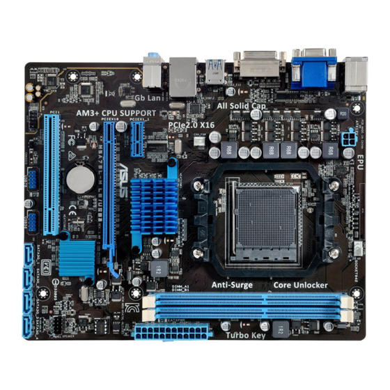
1.2.3 Motherboard layout 19.8cm(7.8in) KBMS_USB34 CPU_FAN ATX12V USB3_E12 1042A CHA_FAN LAN_USB12 ® AUDIO 760G PCIEX1_1 Realtek 8111GR PCIEX16 16Mb M5A78L-M LE/USB3 BIOS Super ® SB710 PCI1 887-VD2 USB78 USB56 SATA3G_1 SATA3G_2 SATA3G_3 SATA3G_4 CLRTC AAFP ASUS M5A78L-M LE/USB3... -
Page 12: Central Processing Unit (Cpu)
5. Speaker connector (4-pin SPEAKER) 1-17 6. System panel connector (10-1 pin F_PANEL) 1-18 7. SATA 3.0 Gb/s connectors (7-pin SATA3G_1~4) 1-17 8. USB 2.0 connectors (10-1 pin USB56, USB78) 1-19 9. Clear RTC RAM (2-pin CLRTC) 1-12 10. Front panel audio connector (10-1 pin AAFP) 1-19 Central Processing Unit (CPU) The motherboard comes with an AM3+ socket designed for AMD FX™ Series/Phenom™ II/ ® Athlon™ II/Sempron™ 100 Series Processors. The AM3+ socket has a different pinout from the AM2+/AM2 socket. Ensure that you usd a CPU designed for the AM3+ socket. The CPU fits in only one correct orientation. DO NOT force the CPU into the socket to prevent bending the pins and damaging the CPU! M5A78L-M LE/USB3 M5A78L-M LE/USB3 CPU socket AM3+ Chapter 1: Product introduction... -
Page 13: Cpu Installation
1.3.1 CPU installation ASUS M5A78L-M LE/USB3... -
Page 14: Cpu Heatsink And Fan Assembly Installation
1.3.2 CPU heatsink and fan assembly installation Apply the Thermal Interface Material to the CPU heatsink and CPU before you install the heatsink and fan if necessary. To install the CPU heatsink and fan assembly Chapter 1: Product introduction... - Page 15 To uninstall the CPU heatsink and fan assembly ASUS M5A78L-M LE/USB3...
-
Page 16: System Memory
Overview This motherboard comes with two Double Data Rate 3 (DDR3) Dual Inline Memory Modules (DIMM) sockets. A DDR3 module has the same physical dimensions as a DDR2 DIMM but is notched differently to prevent installation on a DDR2 DIMM socket. DDR3 modules are developed for better performance with less power consumption. The figure illustrates the location of the DDR3 DIMM sockets: Channel Sockets Channel A DIMM_A1 Channel B DIMM_B1 M5A78L-M LE/USB3 M5A78L-M LE/USB3 240-pin DDR3 DIMM sockets 1.4.2 Memory configurations You may install 1GB, 2GB, 4GB, and 8GB unbuffered non-ECC DDR3 DIMMs into the DIMM sockets. • You may install varying memory sizes in Channel A and Channel B. The system maps the total size of the lower-sized channel for the dual-channel configuration. Any excess memory from the higher-sized channel is then mapped for single-channel operation. • Always install DIMMs with the same CAS latency. For optimal compatibility, we recommend that you install memory modules of the same version or date code (D/C) from the same vendor. Check with the retailer to get the correct memory modules. •... -
Page 17: Installing A Dimm
• The default memory operation frequency is dependent on its Serial Presence Detect (SPD), which is the standard way of accessing information from a memory module. Under the default state, some memory modules for overclocking may operate at a lower frequency than the vendor-marked value. To operate at the vendor-marked or at a higher frequency, refer to section 2.4 Advanced menu for manual memory frequency adjustment. • For system stability, use a more efficient memory cooling system to support a full memory load (2 DIMMs) or overclocking condition. • Visit the ASUS website at: www.asus.com for the latest QVL. 1.4.3 Installing a DIMM ASUS M5A78L-M LE/USB3... -
Page 18: Expansion Slots
To remove a DIMM Expansion slots In the future, you may need to install expansion cards. The following sub-sections describe the slots and the expansion cards that they support. Unplug the power cord before adding or removing expansion cards. Failure to do so may cause you physical injury and damage motherboard components. 1.5.1 Installing an expansion card To install an expansion card: Before installing the expansion card, read the documentation that came with it and make the necessary hardware settings for the card. Remove the system unit cover (if your motherboard is already installed in a chassis). -
Page 19: Pci Slot
OnChip SATA – – – – – – shared – OnChip OHCI 1 shared – – – – – – – OnChip OHCI 2 – – shared – – – – – ASM1042A – – – shared – – – – ASUS M5A78L-M LE/USB3 1-11... -
Page 20: Headers
Headers Clear RTC RAM (2-pin CLRTC) This header allows you to clear the Real Time Clock (RTC) RAM in CMOS. You can clear the CMOS memory of date, time, and system setup parameters by erasing the CMOS RTC RAM data. The onboard button cell battery powers the RAM data in CMOS, which include system setup information such as system passwords. CLRTC M5A78L-M LE/USB3 PIN 1 M5A78L-M LE/USB3 Clear RTC RAM To erase the RTC RAM: Turn OFF the computer and unplug the power cord. Use a metal object such as a screwdriver to short the two pins. Plug the power cord and turn ON the computer. Hold down the <Del> key during the boot process and enter BIOS setup to re- enter data. • If the steps above do not help, remove the onboard battery and short the two pins again to clear the CMOS RTC RAM data. After clearing the CMOS, reinstall the battery. • You do not need to clear the RTC when the system hangs due to overclocking. For system failure due to overclocking, use the CPU Parameter Recall (C.P.R.) feature. Shut down and reboot the system, then the BIOS automatically resets parameter settings to default values. -
Page 21: Connectors
10Mbps connection ORANGE Linked ORANGE 100Mbps connection BLINKING Data activity GREEN 1Gbps connection LAN port Line In port (light blue). This port connects to the tape, CD, DVD player, or other audio sources. Line Out port (lime). This port connects to a headphone or a speaker. In the 2.1, 4.1, 5.1, and 7.1-channel configurations, the function of this port becomes Front Speaker Out. Microphone port (pink). This port connects to a microphone. Refer to the audio configuration table below for the function of the audio ports in 2.1, 4.1, 5.1 or 7.1-channel configuration. ASUS M5A78L-M LE/USB3 1-13... - Page 22 Audio 2.1, 4.1, 5.1 or 7.1-channel configuration Headset Port 4.1-channel 5.1-channel 7.1-channel 2.1-channel Light Blue (Rear Line In Rear Speaker Out Rear Speaker Out Rear Speaker Out panel) Front Speaker Lime (Rear panel) Line Out Front Speaker Out Front Speaker Out Pink (Rear panel) Mic In Mic In Bass/Center Bass/Center Lime (Front panel) — — — Side Speaker Out To configure a 7.1-channel audio output: Use a chassis with HD audio module in the front panel to support a 7.1-channel audio output. USB 2.0 ports 1 and 2. These two 4-pin Universal Serial Bus (USB) ports are for USB 2.0/1.1 devices. USB 3.0 ports 1 and 2. These two 9-pin Universal Serial Bus (USB) ports connect to USB 3.0/2.0 devices.
-
Page 23: Internal Connectors
CPU and chassis fan connectors (4-pin CPU_FAN, 3-pin CHA_FAN) Connect the fan cables to the fan connectors on the motherboard, ensuring that the black wire of each cable matches the ground pin of the connector. CPU_FAN CHA_FAN +12V M5A78L-M LE/USB3 FANIN M5A78L-M LE/USB3 Fan connectors DO NOT forget to connect the fan cables to the fan connectors. Insufficient air flow inside the system may damage the motherboard components. These are not jumpers! DO NOT place jumper caps on the fan connectors. • The CPU_FAN connector supports a CPU fan of maximum 2A (24W) fan power. • Only the 4-pin CPU fan support the ASUS Fan Xpert feature. -
Page 24: Atx Power Connectors
Power OK -5 Volts PIN 1 +5 Volts +5 Volts PSON# +3 Volts -12 Volts M5A78L-M LE/USB3 +3 Volts +3 Volts PIN 1 M5A78L-M LE/USB3 ATX power connectors • We recommend that you use an ATX 12V Specification 2.0-compliant power supply unit (PSU) with a minimum of 300W power rating. This PSU type has 24-pin and 4-pin power plugs. • If you intend to use a PSU with 20-pin and 4-pin power plugs, ensure that the 20-pin power plug can provide at least 15 A on +12 V and that the PSU has a minimum power rating of 300W. The system may become unstable or may not boot up if the power is inadequate. • DO NOT forget to connect the 4-pin ATX +12V power plug. Otherwise, the system will not boot up. - Page 25 Serial ATA 3.0 Gb/s connectors (7-pin SATA3G 1~4) These connectors are for the Serial ATA 3.0 Gb/s signal cables for Serial ATA hard disk drives and optical disc drives. If you installed Serial ATA hard disk drives, you can create a RAID 0, RAID 1, RAID 10 and JBOD configuration through the onboard controller. SATA3G_1 SATA3G_2 SATA3G_3 SATA3G_4 M5A78L-M LE/USB3 M5A78L-M LE/USB3 SATA 3.0Gb/s connectors • These connectors are set to IDE mode by default. If you intend to create a Serial ATA RAID set using these connectors, set the type of the SATA connectors in the BIOS to [RAID]. See section 2.3.4 SATA Configuration for details. • You must install Windows XP Service Pack 3 or later version before using Serial ® ATA hard disk drives. The Serial ATA RAID feature is available only if you are using Windows XP SP3 or later version. ® • When using hot-plug and NCQ, set the type of the SATA connectors in the BIOS to [AHCI]. See section 2.3.4 SATA Configuration for details.
-
Page 26: System Panel Connector
System panel connector (10-1 pin F_PANEL) This connector supports several chassis-mounted functions. F_PANEL +PWR LED PWR BTN PIN 1 M5A78L-M LE/USB3 +HDD_LED RESET M5A78L-M LE/USB3 System panel connector • System power LED (2-pin +PWR_LED) This 2-pin connector is for the system power LED. Connect the chassis power LED cable to this connector. The system power LED lights up when you turn on the system power, and blinks when the system is in sleep mode. • Hard disk drive activity LED (2-pin +HDD_LED) This 2-pin connector is for the HDD Activity LED. Connect the HDD Activity LED cable to this connector. The HD LED lights up or flashes when data is read from or written to the HDD. • ATX power button/soft-off button (2-pin PWR_BTN) This 2-pin connector is for the system power button. - Page 27 AAFP PIN 1 PIN 1 M5A78L-M LE/USB3 HD-audio-compliant Legacy AC’97 pin definition compliant definition M5A78L-M LE/USB3 Front panel audio connector • We recommend that you connect a high-definition front panel audio module to this connector to avail of the motherboard high-definition audio capability. • If you want to connect a high definition front panel audio module to this connector, set the Azalia Front Panel item in the BIOS to [HD]. See section 2.4.4 Onboard Devices Configuration for details. • The front panel audio I/O module is purchased separately. USB 2.0 connectors (10-1 pin USB56, USB78) These connectors are for USB 2.0 ports. Connect the USB module cable to any of...
-
Page 28: Software Support
Ensure that you install Windows XP Service Pack 3 or later versions before installing ® the drivers for better compatibility and system stability. 1.8.2 Support DVD information The Support DVD that comes with the motherboard package contains the drivers, software applications, and utilities that you can install to avail all motherboard features. The contents of the Support DVD are subject to change at any time without notice. Visit the ASUS website at www.asus.com for updates. To run the Support DVD Place the Support DVD into the optical drive. If Autorun is enabled in your computer, the DVD automatically displays the Specials screen. Click Drivers, Utilities, Make Disk, Manual, and Contact tabs to display their respective menus. The following screen is for reference only. Click an icon to display Support DVD/motherboard information Click an item to install If Autorun is NOT enabled on your computer, browse the contents of the Support DVD to locate the file ASSETUP.EXE from the BIN folder. Double-click the ASSETUP.EXE to run... -
Page 29: Chapter 2: Bios Information
BIOS in the future. Copy the original motherboard BIOS using the ASUS Update utility. 2.1.1 ASUS Update utility The ASUS Update is a utility that allows you to manage, save, and update the motherboard BIOS in Windows environment. ®... -
Page 30: Asus Ez Flash 2 Utility
Follow the onscreen instructions to complete the updating process. 2.1.2 ASUS EZ Flash 2 utility The ASUS EZ Flash 2 feature allows you to update the BIOS without using an OS‑based utility. Before you start using this utility, download the latest BIOS file from the ASUS website at www.asus.com. -
Page 31: Asus Crashfree Bios 3
2.1.3 ASUS CrashFree BIOS 3 ASUS CrashFree BIOS 3 is an auto recovery tool that allows you to restore the BIOS file when it fails or gets corrupted during the updating process. You can restore a corrupted BIOS file using the motherboard support DVD or a USB flash drive that contains the updated BIOS file. -
Page 32: Bios Setup Program
• The BIOS setup screens in this chapter are for reference only. They may not exactly match what you see on your screen. • Visit the ASUS website at www.asus.com to download the latest BIOS file for this motherboard. Chapter 2: BIOS information... -
Page 33: Bios Menu Screen
2.2.1 BIOS menu screen Menu items Menu bar Configuration fields General help M5A78L-M LE/USB3 BIOS Setup Version 0211 Main Advanced Power Boot Tools Exit Main Settings Use [ENTER], [TAB] System Time [19:34:30] or [SHIFT-TAB] to System Date [Thu 2/20/2014] select a field. -
Page 34: Menu Items
A configurable field is enclosed in brackets, and is highlighted when selected. To change the value of a field, select it then press <Enter> to display a list of options. Refer to 2.2.7 Pop-up window. M5A78L-M LE/USB3 BIOS Setup Version 0211 2.2.7... -
Page 35: Main Menu
When you enter the BIOS Setup program, the Main menu screen appears, giving you an overview of the basic system information. Refer to section 2.2.1 BIOS menu screen for information on the menu screen items and how to navigate through them. M5A78L-M LE/USB3 BIOS Setup Version 0211 Main Advanced... -
Page 36: Sata Configuration
PIO Mode [Auto] Selects the PIO mode. Configuration options: [Auto] [0] [1] [2] [3] [4] DMA Mode [Auto] Selects the DMA mode. Configuration options: [Auto] SMART Monitoring [Auto] Sets the Smart Monitoring, Analysis, and Reporting Technology. Configuration options: [Auto] [Disabled] [Enabled] 32Bit Data Transfer [Enabled] Enables or disables 32‑bit data transfer. -
Page 37: Advanced Menu
The Advanced menu items allow you to change the settings for the CPU and other system devices. Take caution when changing the settings of the Advanced menu items. Incorrect field values can cause the system to malfunction. M5A78L-M LE/USB3 BIOS Setup Version 0211 Main Advanced... - Page 38 PCIE Overclocking [Auto] Configures the PCIE overclocking. Configuration options: [Auto] [Manual] The following item only appears when you set PCIE Overclocking to [Manual]. PCIE Clock [100] Sets the PCIE Clock. Use <+> / <‑> keys to adjust the ratio or input a number between 100 and 150.
-
Page 39: Dram Timing Configuration
DRAM Command Rate [Auto] Configuration options: [Auto] [1T] [2T] Memory Voltage [Auto] Sets the memory voltage. Configuration options: [Auto] [1.350V] [1.500V] [1.650V] [1.800V] PCI/PCIe CLK Status [Enabled] Enables or disables clock for PCI/PCIe slot. Configuration options: [Disabled] [Enabled] ASUS M5A78L-M LE/USB3 2-11... -
Page 40: Cpu Configuration
2.4.2 CPU Configuration The items in this menu show the CPU‑related information that the BIOS automatically detects. GART Error Reporting [Disabled] This option should remain disabled for the normal operation. The driver developer may enable it for testing purpose. Configuration options: [Disabled] [Enabled] Microcode Updation [Enabled] Enables or disables Microcode Updation. -
Page 41: Chipset
Selects the primary display adapter. Configuration options: [GFX0‑GPP‑IGFX‑PCI] [GPP‑ GFX0‑IGFX‑PCI] [PCI‑GFX0‑GPP‑IGFX] [IGFX‑GFX0‑GPP‑PCI] GFX0: primary video controller on a PCIe x16 slot GPP: primary video controller on a PCIe x1 slot IGFX: onboard display output port PCI: primary video controller on a PCI slot ASUS M5A78L-M LE/USB3 2-13... -
Page 42: Onboard Devices Configuration
UMA Frame Buffer Size [Auto] Selects the UMA frame buffer size. Configuration options: [Auto] [32MB] [64MB] [128MB] [256MB] [512MB] • The [512MB] option only appears when you install 1GB system memory or more. • The [1GB] option only appears when you install 2GB system memory or more. Surround View [Auto] Disables or enables the Surround View function. -
Page 43: Pcipnp
USB hard drives. Setting to Auto allows the system to detect the presence of USB devices at startup. If detected, the USB controller legacy mode is enabled. If no USB device is detected, the legacy USB support is disabled. Configuration options: [Disabled] [Enabled] [Auto] ASUS M5A78L-M LE/USB3 2-15... -
Page 44: Power Menu
The Power menu items allow you to change the settings for the Advanced Configuration and Power Interface (ACPI) and the Advanced Power Management (APM). Select an item then press <Enter> to display the configuration options. M5A78L-M LE/USB3 BIOS Setup Version 0211 Main... -
Page 45: Hw Monitor Configuration
CPU Q-Fan Function [Enabled] Enables or disables the ASUS Q‑Fan feature that smartly adjusts the CPU fan speeds for more efficient system operation. Configuration options: [Disabled] [Enabled] The following items appear only when you set CPU Q-Fan Function to [Enabled]. -
Page 46: Anti Surge Support [Enabled]
CPU Fan Max. Duty Cycle(%) [100%] Allows you to select the maximum CPU fan duty cycle. When the CPU temperature reaches the upper limit, the CPU fan will operate at the maximum duty cycle. Configu- ration options: [20%] [30%] [40%] [50%] [60%] [70%] [80%] [90%] [100%]. CPU Lower Temperature [20 C/68 Displays the lower limit of the CPU temperature. -
Page 47: Boot Menu
Configuration options: [Removable Dev.] [Hard Drive] [ATAPI CD‑ROM] [Disabled] • To select the boot device during system startup, press <F8> when ASUS logo appears. • To access Windows OS in Safe Mode, press <F8> after POST. -
Page 48: Security
AddOn ROM Display Mode [Force BIOS] Sets the display mode for option ROM. Configuration options: [Force BIOS] [Keep Current] Bootup Num-Lock [On] Selects the power‑on state for the NumLock. Configuration options: [Off] [On] Wait for ‘F1’ If Error [Enabled] When this item is set to [Enabled], the system waits for the F1 key to be pressed when error occurs. -
Page 49: Change User Password
Password Check [Setup] When set to [Setup], BIOS checks for user password when accessing the Setup utility. When set to [Always], BIOS checks for user password both when accessing Setup and booting the system. Configuration options: [Setup] [Always] ASUS M5A78L-M LE/USB3 2-21... -
Page 50: Tools Menu
2.7.1 ASUS EZ Flash 2 Allows you to run ASUS EZ Flash 2. When you press <Enter>, a confirmation message appears. Use the left/right arrow key to select between [Yes] or [No], then press <Enter> to confirm your choice. See section 2.1.2 for details. -
Page 51: Exit Menu
Exit menu The Exit menu items allow you to load the optimal or failsafe default values for the BIOS items, and save or discard your changes to the BIOS items. M5A78L-M LE/USB3 BIOS Setup Version 0211 Main Advanced Power Boot... - Page 52 2-24 Chapter 2: BIOS information...
-
Page 53: Federal Communications Commission Statement
Consult the dealer or an experienced radio/TV technician for help. The use of shielded cables for connection of the monitor to the graphics card is required to assure compliance with FCC regulations. Changes or modifications to this unit not expressly approved by the party responsible for compliance could void the user’s authority to operate this equipment. ASUS M5A78L-M LE/USB3... -
Page 54: Canadian Department Of Communications Statement
IC: Canadian Compliance Statement Complies with the Canadian ICES-003 Class B specifications. This device complies with RSS 210 of Industry Canada. This Class B device meets all the requirements of the Canadian interference-causing equipment regulations. This device complies with Industry Canada license exempt RSS standard(s). Operation is subject to the following two conditions: (1) this device may not cause interference, and (2) this device must accept any interference, including interference that may cause undesired operation of the device. - Page 55 ASUS Recycling/Takeback Services ASUS recycling and takeback programs come from our commitment to the highest standards for protecting our environment. We believe in providing solutions for you to be able to responsibly recycle our products, batteries, other components as well as the packaging materials.
- Page 56 Slovenščina AsusTek Inc. tukaj izjavlja, da je ta naprava skladna s di conformità CE. temeljnimi zahtevami in drugimi relevantnimi določili direktiv CE. Za več Компания ASUS заявляет, что это устройство соответствует основным informacij glejte Izjavo CE o skladnosti. требованиям и другим соответствующим условиям европейских...
-
Page 57: Asus Contact Information
+1-510-739-3777 +1-510-608-4555 Web site http://www.asus.com/us/ Technical Support Support fax +1-812-284-0883 Telephone +1-812-282-2787 Online support http://www.service.asus.com/ ASUS COMPUTER GmbH (Germany and Austria) Address Harkort Str. 21-23, D-40880 Ratingen, Germany +49-2102-959911 Web site http://www.asus.com/de Online contact http://eu-rma.asus.com/sales Technical Support Telephone +49-1805-010923* Support Fax... - Page 58 Appendices...
Need help?
Do you have a question about the M5A78L-M LE/USB3 and is the answer not in the manual?
Questions and answers