Table of Contents
Advertisement
Advertisement
Table of Contents

Related Manuals for Asus M4A77T


Summary of Contents for Asus M4A77T
- Page 1 M4A77T...
- Page 2 Product warranty or service will not be extended if: (1) the product is repaired, modified or altered, unless such repair, modification of alteration is authorized in writing by ASUS; or (2) the serial number of the product is defaced or missing.
-
Page 3: Table Of Contents
Contents Notices ... vi Safety information ... vii About this guide ... vii M4A77T specifications summary ... ix Chapter 1: Product introduction Welcome! ... 1-1 Package contents ... 1-1 Special features ... 1-1 1.3.1 Product highlights ... 1-1 1.3.2 Innovative ASUS features ... 1-2 Before you proceed ... - Page 4 Installing an operating system ... 1-27 Support DVD information ... 1-27 BIOS information ASUS Update utility ... 2-1 ASUS EZ Flash 2 ... 2-2 ASUS CrashFree BIOS ... 2-3 BIOS menu screen ... 2-5 Menu bar ... 2-5 Navigation keys ... 2-5 Menu items ...
- Page 5 Boot Device Priority ... 2-18 2.6.2 Boot Settings Configuration ... 2-18 2.6.3 Security ... 2-19 Tools menu ... 2-20 2.7.1 ASUS EZ Flash 2 ... 2-20 2.7.2 Express Gate ... 2-21 2.7.3 AI NET 2... 2-21 Exit menu ... 2-22...
-
Page 6: Canadian Department Of Communications Statement
Complying with the REACH (Registration, Evaluation, Authorisation, and Restriction of Chemicals) regulatory framework, we published the chemical substances in our products at ASUS REACH website at http://green.asus.com/english/REACH.htm. DO NOT throw the motherboard in municipal waste. This product has been designed to enable proper reuse of parts and recycling. -
Page 7: Electrical Safety
Safety information Electrical safety • To prevent electric shock hazard, disconnect the power cable from the electric outlet before relocating the system. • When adding or removing devices to or from the system, ensure that the power cables for the devices are unplugged before the signal cables are connected. If possible, disconnect all power cables from the existing system before you add a device. -
Page 8: Conventions Used In This Guide
Refer to the following sources for additional information and for product and software updates. ASUS websites The ASUS website provides updated information on ASUS hardware and software products. Refer to the ASUS contact information. Optional documentation Your product package may include optional documentation, such as warranty flyers, that may have been added by your dealer. -
Page 9: M4A77T Specifications Summary
Memory Dual-channel memory architecture 4 x 240-pin DIMM slots support maximum 16GB unbuffered ECC * Refer to www.asus.com for the latest Memory QVL (Qualified ** When you install a total memory of 4GB or more, Windows Expansion slots 1 x PCIe x16 slot... - Page 10 1MHz increment – PCIe frequency tuning from 100MHz up to 150MHz at 1MHz increment Overclocking protection: – ASUS C.P.R. (CPU Parameter Recall) 1 x PS/2 Keyboard / Mouse Combo port 1 x LPT port 1 x COM port 1 x LAN (RJ-45) port 6 x USB 2.0/1.1 ports...
-
Page 11: Chapter 1: Product Introduction
® The motherboard delivers a host of new features and latest technologies, making it another standout in the long line of ASUS quality motherboards! Before you start installing the motherboard, and hardware devices on it, check the items in your package with the list below. -
Page 12: Innovative Asus Features
1.3.2 Innovative ASUS features ASUS EPU ASUS EPU is a unique power saving technology that detects the current system loadings and adjusts the power consumption in real time. ASUS Turbo Key ASUS Turbo Key allows you to turn the PC power button into an overclocking button. -
Page 13: Asus Crashfree Bios 3
BIOS file using the bundled support DVD or a USB flash disk that contains the BIOS file. ASUS EZ Flash 2 ASUS EZ Flash 2 allows you to update the BIOS from a USB flash disk before entering the OS. ASUS MyLogo 2™... -
Page 14: Before You Proceed
This motherboard and its packaging comply with the European Union’s Restriction on the use of Hazardous Substances (RoHS). This is in line with the ASUS vision of creating environment-friendly and recyclable products/packaging to safeguard consumers’ health while minimizing the impact on the environment. -
Page 15: Motherboard Overview
Screw holes Place six screws into the holes indicated by circles to secure the motherboard to the chassis. DO NOT overtighten the screws! Doing so can damage the motherboard. Place this side towards the rear of the chassis. ASUS M4A77T... -
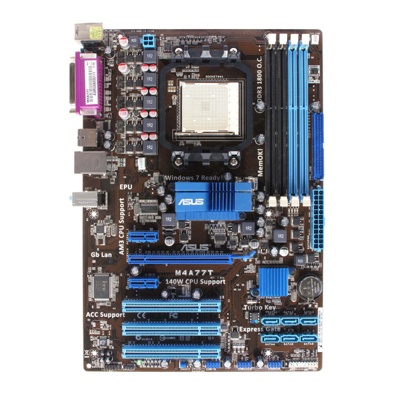
Page 16: Motherboard Layout
1.5.3 Motherboard layout 1.5.4 Layout contents Connectors/Jumpers/Slots/LED CPU and chassis fan connectors (4-pin CPU_FAN and 3-pin CHA_FAN) ATX power connectors (24-pin EATXPWR, 4-pin ATX12V) CPU Socket AM3 DDR3 DIMM slots MemOK! switch IDE connector (40-1 pin PRI_IDE) SATA connectors (7-pin SATA1~6) Page Connectors/Jumpers/Slots/LED 1-20 System panel connector (20-8 pin PANEL) -
Page 17: Central Processing Unit (Cpu)
Carefully insert the CPU into the socket until it fits in place. The CPU fits only in one correct orientation. DO NOT force the CPU into the socket to prevent bending the pins and damaging the CPU! ASUS M4A77T Phenom™ II / Athlon™ II / ® Socket lever Small triangle... - Page 18 When the CPU is in place, push down the socket lever to secure the CPU. The lever clicks on the side tab to indicate that it is locked. Install a CPU heatsink and fan following the instructions that comes with the heatsink package. You can also refer to section 1.6.2 Installing heatsink and fan for instructions.
-
Page 19: Installing The Heatsink And Fan
CPU, heatsink, and the retention mechanism. If the instructions in this section do not match the CPU documentation, follow the latter. Attach one end of the retention bracket to the retention module base. ASUS M4A77T Retention Module Base Retention bracket lock... -
Page 20: System Memory
Align the other end of the retention bracket to the retention module base. A clicking sound denotes that the retention bracket is in place. Ensure that the fan and heatsink assembly perfectly fits the retention mechanism module base, otherwise you cannot snap the retention bracket in place. Push down the retention bracket lock on the retention mechanism to secure the heatsink and fan to the module base. -
Page 21: Memory Configurations
Install a maximum of 3GB system memory if you are using a 32-bit Windows Use a 64-bit Windows motherboard. • This motherboard does not support DIMMs made up of 256 megabits (Mb) chips or less. M4A77T Motherboard Qualified Vendors Lists (QVL) DDR3-1866(O.C.)MHz capability Vendor Part No. - Page 22 DDR3-1600(O.C.)MHz capability Vendor Part No. A-Data AD31600X002GMU Corsair CM3X1G1600C9DHX CRUCIAL BL12864BA1608.8SFB(XMP) CRUCIAL BL12864BE2009.8SFB3(EPP) Crucial BL25664TB1608.K16SF(XMP) Crucial BL25664TG1608.K16SF(XMP) Crucial BL25664TR1608.K16SF(XMP) G.SKILL F3-12800CL9D-2GBNQ G.SKILL F3-12800CL8T-6GBHK G.SKILL F3-12800CL9T-6GBNQ kingmax FLGD45F-B8KG9 kingmax FLGE85F-B8KG9 Kingston KHX12800D3LLK3/3GX(XMP) Kingston KHX12800D3K2/4G Kingston KHX12800D3LLK3/6GX(XMP) We recommend that you install the DDR3 1600+ memory modules on the blue slots for better overclocking performance.
- Page 23 CENTURY PC3-10600 DDR3-1333 9-9-9 Kingtiger 2GB DIMM PC3-10666 Kingtiger KTG2G1333PG3 PATRIOT PSD31G13332H Patriot PSD31G13332 Takems TMS1GB364D081-107EY Takems TMS1GB364D081-138EY ASUS M4A77T Size Chip Brand Chip NO. 1024MB G.SKILL Heat-Sink Package 2048MB G.SKILL Heat-Sink Package 6144MB(Kit Heat-Sink Package of 3 ) 6144MB(Kit...
- Page 24 • C*: Supports two pairs of modules inserted into both the blue slots and the black slots as two pairs of dual-channel memory configuration. Visit the ASUS website at www.asus.com for the latest QVL. 1-14 Chip Size Chip NO.
-
Page 25: Installing A Dimm
Support the DIMM lightly with your fingers when pressing the retaining clips. The DIMM might get damaged when it flips out with extra force. Remove the DIMM from the socket. ASUS M4A77T Unlocked retaining clip Locked Retaining Clip DIMM notch DIMM notch... -
Page 26: Expansion Slots
Expansion slots In the future, you may need to install expansion cards. The following sub-sections describe the slots and the expansion cards that they support. Unplug the power cord before adding or removing expansion cards. Failure to do so may cause you physical injury and damage motherboard components. -
Page 27: To Erase Rtc Ram
• You do not need to clear the RTC when the system hangs due to overclocking. For system failure due to overclocking, use the CPU Parameter Recall (C.P.R) feature. Shut down and reboot the system so the BIOS can automatically reset parameter settings to default values. ASUS M4A77T 1-17... -
Page 28: Memok! Switch
• If the installed DIMMs still fail to boot after the whole tuning process, the DRAM_LED lights continuously. Replace the DIMMs with ones recommended in the Memory QVL (Qualified Vendors Lists) in this user manual or on the ASUS website at www.asus.com. -
Page 29: Connectors
Microphone port (pink). This port connects to a microphone. Refer to the audio configuration table on the next page for the function of the audio ports in a 2, 4, 6, or 8-channel configuration. ASUS M4A77T Speed LED Status Description... -
Page 30: Internal Connectors
DO NOT forget to connect the fan cables to the fan connectors. Insufficient air flow inside the system may damage the motherboard components. These are not jumpers! DO NOT place jumper caps on the fan connectors. Only the 4-pin CPU fan supports the ASUS Q-Fan feature. 1-20 Headset 2-channel... - Page 31 The system may become unstable or may not boot up if the power is inadequate. • If you are uncertain about the minimum power supply requirement for your system, refer to the Recommended Power Supply Wattage Calculator at http://support.asus. com/PowerSupplyCalculator/PSCalculator.aspx?SLanguage=en-us for details. ASUS M4A77T...
-
Page 32: Ide Connector (40-1 Pin Pri_Ide)
IDE connector (40-1 pin PRI_IDE) The onboard IDE connector is for Ultra DMA 133/100/66 signal cable. There are three connectors on each Ultra DMA 133/100/66 signal cable: blue, black, and gray. Connect the blue connector to the motherboard’s IDE connector, then select one of the following modes to configure your devices: Single device Two devices... - Page 33 • For more details on RAID/AHCI, refer to the RAID/AHCI Supplementary Guide included in the folder named Manual in the support DVD. ASUS M4A77T XP Service Pack 2 or later versions before using Serial ATA. ® XP operating system on a hard disk drive ®...
-
Page 34: System Panel Connector
System panel connector (20-8 pin PANEL) This connector supports several chassis-mounted functions. • System power LED (2-pin PLED) This 2-pin connector is for the system power LED. Connect the chassis power LED cable to this connector. The system power LED lights up when you turn on the system power, and blinks when the system is in sleep mode. -
Page 35: Digital Audio Connector (4-1 Pin Spdif_Out)
• If you want to connect a high definition front panel audio module to this connector, set the Front Panel Select item in the BIOS to [HD Audio]. See section 2.4.4 Onboard Devices Configuration for details. • The front panel audio I/O module is purchased separately. ASUS M4A77T 1-25... -
Page 36: Usb Connectors
USB connectors (10-1 pin USB78, USB910, USB1112) These connectors are for USB 2.0 ports. Connect the USB module cable to any of these connectors, then install the module to a slot opening at the back of the system chassis. These USB connectors comply with USB 2.0 specification that supports up to 480Mbps connection speed. -
Page 37: Software Support
The contents of the Support DVD are subject to change at any time without notice. Visit the ASUS website at www.asus.com for updates. To run the Support DVD Place the Support DVD into the optical drive. - Page 38 1-28 Chapter 1: Product introduction...
-
Page 39: Bios Information
BIOS in the future. Copy the original motherboard BIOS using the ASUS Update utility. 2.1.1 ASUS Update utility The ASUS Update is a utility that allows you to manage, save, and update the motherboard BIOS in Windows environment. ®... -
Page 40: Asus Ez Flash 2
Follow the onscreen instructions to complete the updating process. 2.1.2 ASUS EZ Flash 2 The ASUS EZ Flash 2 feature allows you to update the BIOS without using an OS-based utility. Before you start using this utility, download the latest BIOS file from the ASUS website at www.asus.com. -
Page 41: Asus Crashfree Bios
2.1.3 ASUS CrashFree BIOS The ASUS CrashFree BIOS is an auto recovery tool that allows you to restore the BIOS file when it fails or gets corrupted during the updating process. You can restore a corrupted BIOS file using the motherboard support DVD or a removable device that contains the updated BIOS file. -
Page 42: Entering Bios Setup At Startup
• The BIOS setup screens in this chapter are for reference only. They may not exactly match what you see on your screen. • Visit the ASUS website at www.asus.com to download the latest BIOS file for this motherboard. Chapter 2: BIOS information... -
Page 43: Bios Menu Screen
At the bottom right corner of a menu screen are the navigation keys for that particular menu. Use the navigation keys to select items in the menu and change the settings. Some of the navigation keys differ from one screen to another. ASUS M4A77T Configuration fields BIOS SETUP UTILITY... -
Page 44: Menu Items
2.2.4 Menu items The highlighted item on the menu bar displays the specific items for that menu. For example, selecting Main shows the Main menu items. The other items (Advanced, Power, Boot, Tools, and Exit) on the menu bar have their respective menu items. -
Page 45: Main Menu
CD-ROM drive. Select [ARMD] (ATAPI Removable Media Device) if your device is either a ZIP, LS-120, or MO drive. Configuration options: [Not Installed] [Auto] [CDROM] [ARMD] This item only appears in the Primary IDE Master/Slave and SATA5/6 menus. ASUS M4A77T BIOS SETUP UTILITY Boot... -
Page 46: Sata Configuration
LBA/Large Mode [Auto] Enables or disables the LBA mode. Setting this item to [Auto] enables the LBA mode if the device supports this mode, and if the device was not previously formatted with LBA mode disabled. Configuration options: [Disabled] [Auto] Block (Multi-Sector Transfer) M [Auto] Enables or disables data multi-sectors transfers. -
Page 47: System Information
CPU Level Up [Auto] Selects the desired CPU level, and other relevant parameters will be adjusted automatically based on the selected CPU level. Configuration options: [Auto] [Phenom II-955] [Phenom II-3.4G] [Phenom II-3.6G] ASUS M4A77T BIOS SETUP UTILITY Boot Tools Exit... -
Page 48: Loadline Calibration [Auto]
Ai Overclock Tuner [Auto] Selects the CPU overclocking options to achieve desired CPU internal frequency. Configuration options: [Manual] [Auto] [Overclock Profile] [Test Mode] [CPU Level Up] The following items only appear when you set Ai Overclock Tuner to [Manual]. OC From CPU Level Up [200] Selects the desired CPU level, and other relevant parameters will be adjusted automatically based on the selected CPU level. -
Page 49: Dram Frequency [Auto]
Configuration options: [Auto] [5 CLK] [6 CLK] [7 CLK] [8 CLK] [10 CLK] [12 CLK] TRRD [Auto] Configuration options: [Auto] [4 CLK] ~ [7 CLK] TRWTTO [Auto] Configuration options: [Auto] [3 CLK] ~ [17 CLK] TWRRD [Auto] Configuration options: [Auto] [2 CLK] ~ [10 CLK] ASUS M4A77T 2-11... -
Page 50: Cpu Configuration
TWTR [Auto] Configuration options: [Auto] [4 CLK] ~ [7 CLK] TWRWR [Auto] Configuration options: [Auto] [3 CLK] ~ [10 CLK] TRDRD [Auto] Configuration options: [Auto] [3 CLK] ~ [10 CLK] TRFC0/1 [Auto] Configuration options: [Auto] [90ns] [110ns] [160ns] [300ns] [350ns] TREF [Auto] Configuration options: [Auto] [Every 7.8ms] [Every 3.9ms] DCT0:CKE drive strength [Auto] / DCT1:CKE drive strength [Auto]... -
Page 51: Chipset
Configuration options: [Disabled] [Enabled] DCT Unganged Mode [Always] Allows you to select the unganged DRAM mode (64-bit width). Configuration options: [Auto] [Always] Power Down Enable [Disabled] Allows you to enable or disable DDR power down mode. Configuration options: [Disabled] [Enabled] ASUS M4A77T 2-13... -
Page 52: Ecc Configuration
ECC Configuration ECC Mode [Disabled] Enables or disables the DRAM ECC that allows the hardware to report and correct memory errors automatically. Configuration options: [Disabled] [Basic] [Good] [Super] [Max] [User] Primary Display Adapter [GFX-GPP-PCI] Allows you to set the primary display adapter. Configuration options: [GFX-GPP-PCI] [GPP- GFX-PCI] [PCI-GFX-GPP] GFX: primary display adapter on the PCIe x16_1 slot GPP: primary display adapter on the PCIe x16_2 or PCIe x1 slot... -
Page 53: Pcipnp
Sets the maximum time that the BIOS waits for the USB storage device to initialize. Configuration options: [10 Sec] [20 Sec] [30 Sec] [40 Sec] Emulation Type [Auto] Allows you to set the emulation type. Configuration options: [Auto] [Floppy] [Forced FDD] [Hard Disk] [CDROM] ASUS M4A77T 2-15... -
Page 54: Power Menu
Power menu The Power menu items allow you to change the settings for the Advanced Configuration and Power Interface (ACPI) and the Advanced Power Management (APM). Select an item then press <Enter> to display the configuration options. Main Advanced Power Settings Suspend Mode ACPI 2.0 Support ACPI APIC support... -
Page 55: Hw Monitor Configuration
Select [Ignored] if you do not want the detected voltage to be displayed. Smart Q-Fan Function [Enabled] Allows you to enable or disable the ASUS Q-Fan feature that smartly adjusts the CPU fan speed for more efficient system operation. Configuration options: [Disabled] [Enabled] Fan Auto Mode Start Voltage [5.0V]... -
Page 56: Boot Menu
Configuration options: [Removable Dev.] [Hard Drive] [ATAPI CD-ROM] [Disabled] • To select the boot device during system startup, press <F8> when ASUS Logo appears. • To access Windows •... -
Page 57: Bootup Num-Lock [On]
View Only allows access but does not allow change to any field. Limited allows changes only to selected fields, such as Date and Time. Full Access allows viewing and changing all the fields in the Setup utility. ASUS M4A77T 2-19... -
Page 58: Tools Menu
(C)Copyright 1985-2009, American Megatrends, Inc. 2.7.1 ASUS EZ Flash 2 Allows you to run ASUS EZ Flash 2. When you press <Enter>, a confirmation message appears. Use the left/right arrow key to select between [Yes] or [No], then press <Enter> to confirm your choice. -
Page 59: Express Gate
2.7.2 Express Gate [Auto] Enables or disables the ASUS Express Gate feature. ASUS Express Gate is a unique instant-on environment that provides quick access to the Internet and Skype. Configuration options: [Disabled] [Enabled] [Auto] Enter OS Timer [10 Seconds] Sets countdown duration that the system waits at the Express Gate’s first screen before starting Windows or other installed OS. -
Page 60: Exit Menu
Exit menu The Exit menu items allow you to load the optimal or failsafe default values for the BIOS items, and save or discard your changes to the BIOS items. Main Advanced Exit Options Exit & Save Changes Exit & Discard Changes Discard Changes Load Setup Defaults Pressing <Esc>...
Need help?
Do you have a question about the M4A77T and is the answer not in the manual?
Questions and answers