Table of Contents

Summary of Contents for Abrams Logic 1100
- Page 1 LGS-1100-H Abrams Logic 1100 Programmable Handheld Siren System & Light Controller Firmware Ver. A/B and Ver. C/B NOTICE TO INSTALLER Before installation and operation ― read all instructions and warnings. Deliver this manual to the end user of this product.
-
Page 2: Table Of Contents
TABLE OF CONTENTS WARNING ......................1 CONTENTS ...................... 2 SPECIFICATIONS .................... 2 WIRING......................3 CONTROLLER FUNCTION ................5 PROGRAMMING....................5 INSTALLATION ....................9 WARNING 1. Proper installation of the product requires the installer to have a good understanding of automotive electronics, systems and procedures. -
Page 3: Contents
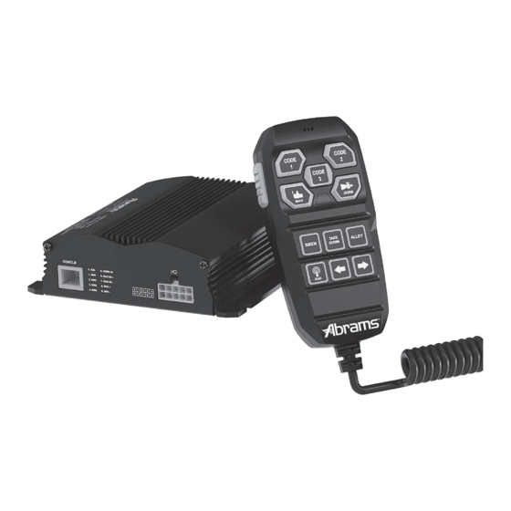
CONTENTS Front View Siren amplifier x 1 pc Control wire harness x 1 pc (30cm) Terminal block x 1 pc Sheet metal screws x 4 pcs (ø3/16" x 3/4") Rear View Tooth lock washers x 4 pcs ... -
Page 4: Wiring
WIRING ● Wire Gage vs Maximum Current Draw Through The Wire FEET METERS (American Wire Gauge) (IEC 60228:2004 Standard Wire Cross-Section) 22AWG 20AWG 18AWG 16AWG 14AWG 12AWG 10AWG 8AWG 6AWG 0.5mm² 0.75mm² 1mm² 1.5mm² 2.5mm² 4mm² 6mm² 10mm² 16mm² 3′ 5′... - Page 5 Power Wire Terminal Block (Connector A) ● Power +VDC & -GND 1. Connect to the positive (+) battery terminal. Fuse each wire independently @35 Amps (user-supplied). DO NOT install these fuses until the wiring for the entire system has been completed. 2.
-
Page 6: Controller Function
CONTROLLER FUNCTION Before any operation, apply positive voltage to the IGN (Ignition) wire at the rear to power-up the unit. Button Decal PTT: Activate Microphone for PA Broadcast through the siren speaker. This Button overrides all other acoustic function (i.e. Air Horn, Siren Tone and Radio Rebroadcast) while it is activated. - Page 7 3. Once set, press PTT and HORN buttons for 5 seconds to save and exit Tone Cycle Setting. Code 2 will stop blinking to indicate that you have exited. INDICATION CHART: TONE CYCLE COUNTRY TONE FREQUENCY CYCLE/MINUTE RADIO SW3 (Hz) 761-1592 WAIL 12 C/M 761-1592...
- Page 8 Volume Adjustment PA, Siren and Radio Re-broadcasting may be set to different INDICATION CHART Volume Level (total of 8 levels, default at 8). 1. Press and hold PTT, MAN and Code 1 for 5 seconds to enter Volume Adjustment Setting. 2.
- Page 9 Code Button Combo Setting Code 1, Code 2 and Code 3 buttons may be programmed to turn on and off switch button controls (SW1~SW4) and/or SIREN button together. 1. Press and hold PTT, MAN and RADIO for 5 seconds to enter Code Button Combo Setting. RADIO will blink to indicate that you are in Code Button Combo Setting.
-
Page 10: Installation
INSTALLATION Mounting ● Siren amplifier 1. Select a location that is not exposed directly to weather elements, such as the driver compartment firewall, below the seat, or in the trunk; avoid any interference of air bag deployment. 2. Using the siren amplifier as a template, mark four mounting holes to be drilled. 3.
Need help?
Do you have a question about the Logic 1100 and is the answer not in the manual?
Questions and answers