
Related Manuals for Viking CRVER3301


Summary of Contents for Viking CRVER3301
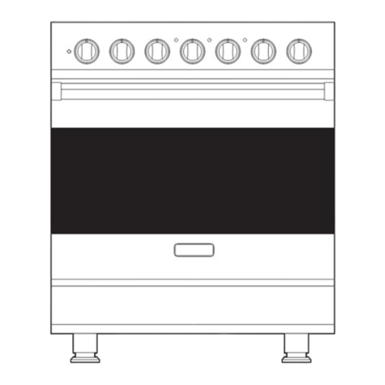
- Page 1 Installation 3 Series Freestanding 30” Electric Self-Clean Range RVER3301 / CRVER3301...
-
Page 2: Table Of Contents
Table of Contents Warnings & Important Safety Instructions _______________________________________________3 Dimensions _________________________________________________________________________6 Specifications _______________________________________________________________________7 Clearance Dimensions (Proximity to Cabinets) ___________________________________________8 Clearance Dimensions (Wood/Composite Overlay) ______________________________________9 Electrical Requirements _____________________________________________________________10 General Information ________________________________________________________________12 Installation _________________________________________________________________________13 Backguard Installation _______________________________________________________13 Door Removal ______________________________________________________________13 Leg Installation______________________________________________________________14 Electrical Connection (3-wire) _________________________________________________15 Electrical Connection (4-wire) _________________________________________________17 Leveling/Adjustments/Alignment ______________________________________________19... - Page 3 –Read and Follow! IMPORTANT • Before beginning, please read these Your safety and the safety of others is instructions completely and carefully. very important. We have provided many important safety • DO NOT remove permanently affixed messages in this manual and on your labels, warnings, or plates from product.
- Page 4 • The required use of a GFI is normally related to the location of a receptacle with respect to any significant sources of water or moisture. • Viking Range, LLC will NOT warranty any problems resulting from GFI outlets which are not installed properly or do not meet the requirements below.
- Page 5 WARNING WARNING TIPPING HAZARD ELECTRICAL SHOCK HAZARD To reduce the risk of the appliance tipping, it must be To avoid risk of electrical shock, secured by a properly installed personal injury or death; verify anti-tip bracket(s). To make your appliance has been properly sure the bracket has been grounded in accordance with local codes installed properly, look behind...
-
Page 6: Dimensions
Dimensions RVER/CRVER - 7 / ( 7 5 8 ” ( 9 1 - 7 / 8 ” i n . ( 9 4 ” 27-1/8” (68.9 cm) 25” (63.5 cm) 6” (15.2 cm) 29” (73.7 cm) 35-7/8” (91.1 cm) min. 25”... -
Page 7: Specifications
Specifications Electric 30” Range Description RVER/CRVER Overall width 29-7/8” (75.9 cm) Overall height To top of glass frame 35-7/8” (91.1 cm) min. to 37” (94.0 cm) max. Legs adjust 1-1/8” (2.9 cm) Overall depth from rear To end of side panel—25” (63.5 cm) To front of door—25-3/4”... -
Page 8: Clearance Dimensions (Proximity To Cabinets)
Clearance Dimensions (Proximity to Cabinets) • This range may be installed directly adjacent CAUTION to existing 36” (91.4 cm) high base cabinets. To prevent possible damage to cabinets IMPORTANT: The side trim MUST be and cabinet finishes, use only materials 3/8”... -
Page 9: Clearance Dimensions (Wood/Composite Overlay)
Clearance Dimensions (Wood/Composite Overlay) The bottom of a standard hood should be 30” (76.2 cm) min. to 36” (91.4 cm) max. / C o above the countertop. This would typically o s i e r l result in the bottom of the hood being 66”... -
Page 10: Electrical Requirements
Electrical Requirements Electrical Requirements Viking Range, LLC will NOT warranty any This product is manufactured with the problems resulting from GFI outlets which neutral terminal connected to the cabinet. are not installed properly or do not meet the Use a 3-wire, agency approved, power requirements below. - Page 11 Electrical Requirements Electric access area 6” (15.2 cm) 3-1/2” (8.9 cm) 6” 4-3/8” 4-3/8” 4-3/8” (15.2 cm) (11.1 cm) (11.1 cm) (11.1 cm) 3” (7.6 cm) SIDE VIEW REAR VIEW...
-
Page 12: General Information
MUST be installed with one unusual or excessive noise coming from the of the anti-tip devices. cooling fan, contact a Viking Authorized Service Center before continuing operation. Refer to “Anti-tip Device Installation” Failure to do so can result in damage to the section. -
Page 13: Installation
Installation CAUTION To avoid risk of personal injury or product damages, DO NOT use the handle or oven door to lift the oven. Remove door before installation to ensure that it is not used to lift the unit. DO NOT lift or carry the door by the handle. -
Page 14: Leg Installation
Leg Installation Legs are packed in styrofoam top pack. Note: It is strongly recommended Note: Legs should be installed near to where that a pallet or lift jack be used rather than tilting. appliance is to be used, as they are Raise unit about a foot. -
Page 15: Electrical Connection (3-Wire)
Electrical Connection (3-wire) Note: If you have a 4-wire connection, see following section for 4-wire connection instructions. WARNING WARNING ELECTRICAL SHOCK ELECTRICAL SHOCK HAZARD HAZARD To avoid risk or electrical To avoid risk of electrical shock, shock, personal injury or death; personal injury or death;... - Page 16 Electrical Connection (3-wire) (cont.) Bare Wire Connection Eyelet Connection To make a bare wire connection, use holes on the left Attach line #1 (black) and line #2 (red) side of the terminal block. To connect eyelet style leads to outside terminal. Attach neutral wire (white) wires, use holes on right side of terminal.
-
Page 17: Electrical Connection (4-Wire)
Electrical Connection (4-wire) WARNING WARNING ELECTRICAL SHOCK ELECTRICAL SHOCK HAZARD HAZARD To avoid risk or electrical To avoid risk of electrical shock, shock, personal injury or death; personal injury or death; verify grounding product to the frame of the unit your appliance has been properly may or may not be permitted through grounded in accordance with local codes... - Page 18 Electrical Connection (4-wire) (cont.) Bare Wire Connection Eyelet Connection Feed supply cord up through hole in bottom To make a bare wire connection, use holes on the left side of the terminal block. To connect eyelet style of range back. wires, use holes on right side of terminal.
-
Page 19: Leveling/Adjustments/Alignment
Leveling/Adjustments/Alignment Measure the four corners in cutout area to For uneven or sloped floors, level unit with verify if flooring is level. metal shims only, as the adjustment required may exceed the thread available in the leg. ” ” ” 3 / 8 3 / 8 3 / 8... -
Page 20: Anti-Tip Device Installation
Leveling/Adjustments/Alignment (cont.) Set the high corner of range so that the top of side trim is 3/8” (0.95 cm) above countertop. Level range to high corner. Anti-tip Device Installation WARNING WARNING TIPPING HAZARD TIPPING HAZARD To reduce the risk of the •... -
Page 21: Wall Mount Anti-Tip Installation
Wall Mount Anti-tip Installation 3 - 5 3 - 5 3 - 5 ( 9 . ( 9 . ( 9 . ” ” ” ( 1 . ( 1 . ( 1 . / 2 ” / 2 ” / 2 ”... -
Page 22: Floor Mount Anti-Tip Installation
Floor Mount Anti-tip Installation 3-7/8“ Dim A from Rear Wall WIthout Standoffs (9.8 cm) Dim A from Rear Wall 4-5/8” 8 - 1 8 - 1 8 - 1 WIth Standoffs (11.7 cm) ( 2 1 ( 2 1 ( 2 0 ”... -
Page 23: Final Installation
Final Installation Connect electrical in shaded area. See the “Electrical Slide range into place. Be sure anti-tip Requirements” section for more information. bracket slides into the anit-tip opening. ” ” ” 3 / 8 3 / 8 3 / 8 ( 0 . -
Page 24: Door Replacement
Door Replacement Open door completely. Carefully realign door on hinges. Fold latches forward until locked in place. Slide in and down. Close door... -
Page 25: Final Preparation
Final Preparation • All stainless steel body parts should be to remove encrusted materials, soak with wiped with hot, soapy water and with a hot, wet cloths to loosen the material, then liquid cleaner designed for this material. use a wool or nylon scraper. DO NOT use If buildup occurs, DO NOT use steel wool, a metal knife, spatula, or any other abrasive cloths, cleansers, or powders! -
Page 26: Service & Registration
Only authorized replacement parts may be used in performing service on the appliance. All servicing should be referred to a qualified technician. Contact Viking Range, LLC, 1-888-845-4641, for the nearest service parts distributor in your area or write to: VIKING RANGE, LLC... - Page 28 Viking Range, LLC 111 Front Street Greenwood, Mississippi 38930 USA (662) 455-1200 For product information, call 1-888-845-4641 or visit our website at vikingrange.com (093018) F21193C EN...
Need help?
Do you have a question about the CRVER3301 and is the answer not in the manual?
Questions and answers