Table of Contents
Advertisement
Quick Links
Advertisement
Table of Contents

Related Manuals for ROBOfiber HGW-2402A-PSE

Summary of Contents for ROBOfiber HGW-2402A-PSE
- Page 1 User Manual HGW-2402A-PSE 24 port Gigabit Unmanaged Industrial Smart PoE Switch...
- Page 2 User Manual This manual introduces ROBOfiber’s HGW-2402A-PSE Gigabit switch installation procedures, operation settings and user safety operating aspects. Contents: Introduction: PoE switch functions, features and physical appearance. Installation: basic installation guide for the PoE switch with necessary precautions for proper operation.
-
Page 3: Switch Description
Industrial Gigabit Smart Unmanaged PoE switch with 24 10/100/1000Mbps PoE ports and 2 Gigabit SFP uplink ports. HGW-2402A-PSE can deliver PoE power to end devices such as IP cameras, wireless AP/bridge devices or IP phones. Switch has DIP switch settings for 4 distinctive operating modes. In AI VLAN mode switch has all 24 ports isolated from each other, to prevent network storms and improve network performance. -
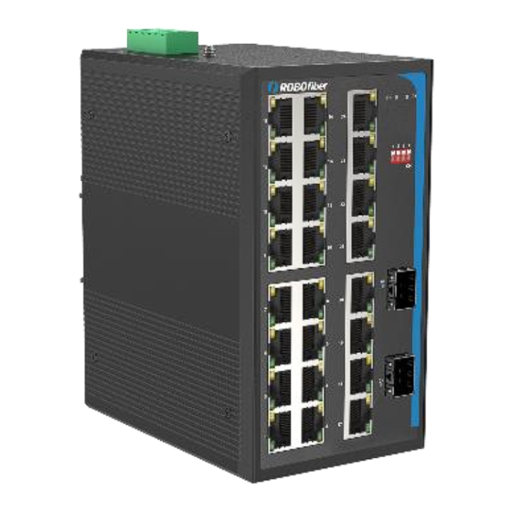
Page 4: Physical Appearance
IEEE802.3at standards. When set up in Extend mode (via DIP switches), port 1 to 24 can support 250m line PoE power at 10M speed only. SFP Ports HGW-2402A-PSE has two gigabit SFP ports (25, 26) requiring Gigabit rated SFP modules. DIP Switch Mode Settings ... - Page 5 Rear panel image ◼ Power Terminal Block 6 screw power terminal block offers PWR1 and PWR2 DC48V input for HGW-2402A-PSE switch; power supply requirement is DC 48-56V(no power switch to eliminate accidental shutdown). Ground Terminal Screw ...
-
Page 6: Installation
Installation Warning:Incorrect usage of this device can cause property damage and personal injury, please read carefully the list below before using the equipment: Please keep device unplugged from power sources during installation, wear ⚫ anti-static bracelet if available Please make sure that power source voltage matches requirements for power ⚫... - Page 7 Installation HGW-2402A-PSE switch is designed to be installed on a standard TS-35 DIN rail. Installation on rail should follow below diagram. For wall mounting the position of the wall brackets should change as above. Note: Before screwing the screws into the wall, make sure that the screw size matches the wall-mounting metal panels of the HGW-2402A-PSE switch.
-
Page 8: Rj45 Port Connections
Connectivity 3.1 RJ45 port connections Connect regular network equipment or PoE PD devices to any UTP ports 1 to 24 like in below diagram. -
Page 9: Sfp Ports
Ethernet cables can be used for network connectivity (please use Cat5e cabling or better) 3.2 SFP ports HGW-2402A-PSE SFP ports only support gigabit SFP modules. Please use Gigabit rated (1.25G) SFPs with the switch. Installing the SFP transceiver module: Hold the SFP module from the side, insert it smoothly along the SFP port slot of PoE switch, until a soft click is heard, denoting SFP is secure to switch;... -
Page 10: Hardware Specifications
Hardware Specifications 4.1 Technical Specifications IEEE 802.3i, IEEE 802.3u, IEEE 802.3x Standards IEEE 802.3ab, IEEE 802.3af, IEEE 802.3at 24x 10/100/1000Mbps RJ45 ports Ports 2x Gigabit SFP ports 24x 10/1000Mbps RJ45 PoE ports Total power budget: 480W Single port max. budget: 30W 26 Link/Act indicator lights Indicators 2 Power indicator lights...
Need help?
Do you have a question about the HGW-2402A-PSE and is the answer not in the manual?
Questions and answers