Advertisement
Quick Links
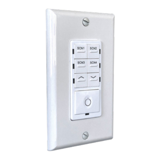
7 Button AC Powered Wall Switch (BCS05)
Installation Instructions
Wire Nuts
Switch
Wall plate
with mount screws
Screws
WHAT COMES IN THE BOX
Screws (2)
Switch
Installation instructions
Wall plate with mount screws
Wire nuts (3)
ATTENTION
1.
Please check if there is any damage during shipping. If so, please contact Litetronics
customer service.
2.
Please read the installation instruction carefully to check whether all the
accessories are included.
3.
After confirmation, install the switch according to installation steps.
Tip: This Bluetooth device is compatible with Litetronics lighting control system only.
WARNINGS
Risk of fire or electric shock. The 7 Button AC Powered Wall Switch installation requires knowledge
of electrical systems. If not qualified, do not attempt installation. Contact a qualified electrician.
Be certain electrical power is OFF before and during installation and maintenance.
Risque d'incendie ou d'électrocution. L'installation de l'interrupteur mural à 7 boutons alimenté en courant alternatif
nécessite une connaissance des systèmes électriques. Si vous n'êtes pas qualifié, ne tentez pas l'installation. Contactez un
électricien qualifié.
Assurez-vous que l'alimentation électrique est coupée avant et pendant l'installation et l'entretien.
SAFETY INSTRUCTIONS
WHEN USING ELECTRICAL EQUIPMENT, BASIC SAFETY PRECAUTIONS SHOULD ALWAYS BE OBSERVED.
READ CAREFULLY BEFORE INSTALLING FIXTURE. RETAIN THESE INSTRUCTIONS FOR FUTURE
REFERENCE.
Litetronics switches must be wired in accordance with the National Electrical Code and all applicable
local codes.
7 Button AC Powered Wall Switch must be connected to a wiring system with an
equipment – grounding conductor.
Make sure the supply voltage is the same as the rated switch voltage.
To prevent wiring damage or abrasion, do not expose wiring to edges of sheet metal
or sharp objects.
1
8/2/23 - V1.2
SWITCH FUNCTIONALITY
2
Dim Up
4
ON / OFF
TOOLS NEEDED
Note: Install LiteSmart App first and make sure light fixtures to be paired are added
Phillips and flathead screwdriver
to the App before setting the switch.
WIRING DIAGRAM
WIRING
1.
Turn the power off.
2.
Remove wall plate, switch mounting screws from existing switch.
3.
Carefully remove the existing switch from the switch box.
DO NOT disconnect the wires.
4.
There are three wiring connections on the switch, these are marked HOT, NEUTRAL,
GROUND.
5.
Disconnect the wires from the existing switch.
6.
Connect the green wire to the GROUND terminal. Connect the white wire to the
terminal marked NEUTRAL. Connect the black wire to the terminal marked HOT.
See Figure 1.
7.
Check connections to be sure they are tight and no bare conductors are exposed.
8.
Insert the switch into the outlet box carefully.
9.
Mount the switch to the box using the supplied screws.
10.
Attach the wall plate and replace plate screws.
11.
Restore power to the circuit breaker and test the system.
Tip: This Bluetooth device is compatible with Litetronics LiteSmart lighting control system only.
DOWNLOAD THE LITESMART APP
1
Scene Buttons:
Allows selection of 4 scenes
set up through app.
3
Dim Down
5
Indicator Lights
SWITCH SET UP
1.
Figure 1
• Wire Strip Length; 16 mm (5/8 in.)
• The switch installs into a standard outlet box.
2.
3.
4.
5.
6.
Flip to continue
2
LITESMART
1.
Download the LiteSmart mobile app for iOS or Android.
Scan QR code below.
Go to the Switches page and tap + icon to add a new switch.
LiteSmart will scan for recognizable switches.
2
3
On the switch, press buttons
and
(see switch functionality
illustration) together over 2 seconds to enter pairing mode or activate
reset function. This switch can be rescanned in the next 30 seconds.
Tap Done
Choose the new switch by tapping on the Gear/settings icon.
Rename the switch by tapping on the name. Rename and tap Save.
3
ID001
Advertisement

Related Manuals for LITETRONICS BCS05


Summary of Contents for LITETRONICS BCS05
- Page 1 Connect the green wire to the GROUND terminal. Connect the white wire to the REFERENCE. terminal marked NEUTRAL. Connect the black wire to the terminal marked HOT. Litetronics switches must be wired in accordance with the National Electrical Code and all applicable See Figure 1. local codes.
- Page 2 This information is subject to change without notice and without incurring liability. If you have questions regarding specific product details, please contact us at 800-860-3392 or via email at customerservice@litetronics.com. To check for an updated version of these instructions, please visit www.litetronics.com.
Need help?
Do you have a question about the BCS05 and is the answer not in the manual?
Questions and answers