Table of Contents
Advertisement
Quick Links
Advertisement
Table of Contents

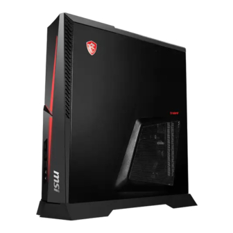
Summary of Contents for MSI Trident Series
- Page 1 Trident Series Personal Computer Trident B924 Service Guide...
-
Page 2: Table Of Contents
Contents How to Use this Service Guide ..................3 Necessary Tools ......................3 Safety Precautions ....................... 3 Other Notice ........................4 Upgrade and Warranty ....................4 Acquisition of Replaceable Parts ................4 Removing Side Cover ....................5 Right Side View ......................6 Left Side View ........................ -
Page 3: How To Use This Service Guide
∙ Place system components on a grounded antistatic pad or on the bed that came with the components whenever the components are separated from the system. ∙ If there are any difficulties installing hardware devices, please contact MSI for further information. -
Page 4: Other Notice
2 years at most since the product has been discontinued, depending on the official regulations declared at the time. Please contact the manufacturer via https://www.msi.com/support/ for the detailed information about the acquisition of spare parts. Other Notice... -
Page 5: Removing Side Cover
Removing Side Cover ⚠ Important Before you remove or install any components, make sure the system is not turned on or connected to the power. 1. Place the system on a flat and steady surface. Unlock the screws and keep the screws for later use. -
Page 6: Right Side View
Right Side View 2.5” HDD CPU & CPU Cooler Memory Module Left Side View Graphics Card M.2 SSD ⚠ Important Reference image only. Appearance will vary. Right Side View... -
Page 7: Removing Cpu Cooler
Removing CPU Cooler 1. Unlock screws of the CPU fan module. 2. Remove screws on the CPU thermal module. 3. Unplug the power cable and the RGB LED cable Follow the above procedures in ∙ reversed order to replace the CPU cooler if needed. -
Page 8: Installing Cpu
Installing CPU 1. Open the load lever. 2. Lift the load lever and load plate up to fully open position. 3. After confirming the CPU direction for correct mating, lower the CPU straight down without tilting or sliding the CPU in the socket. Inspect the CPU to check if it is properly seated in the socket. - Page 9 4. Close and slide the load plate under the retention knob. 5. Close the load lever. 6. Secure the load lever with the hook under the retention tab. Follow the above procedures in ∙ reverse order to replace the CPU if needed.
-
Page 10: Installing Memory
Installing Memory 1. Flip the slot clips outwards. 2. Align the notch on the memory with the key on the slot and insert the memory into the slot with correct orientation. Push the memory module gently downwards until the slot clips click and lock the memory in place. -
Page 11: Installing 2.5" Hdd
Installing 2.5” HDD 1. Put the bracket to the 2.5” HDD and lock the screws. 2. Locate the HDD and connect the power and signal cables. 3. Secure the bracket. ∙ Follow the above procedures in reverse order to replace the HDD if needed. -
Page 12: Installing Graphics Card
Installing Graphics Card ⚠ Important Reference image only. Graphics card appearance will vary. 1. Unlock the screws that secures the top cover. 2. Open the top cover. 3. Lock the screws of the auxiliary graphics card support to secure the bracket. - Page 13 ⚠ Important When removing the graphics card, you need to press the clip to release it. 5. Lock the screws of the auxiliary graphics card support. 6. Connect the power connectors to finish. ∙ Follow the above procedures in reverse order to replace the graphics card if needed.
-
Page 14: Installing M.2 Ssd (Optional)
Installing M.2 SSD (Optional) 1. Locate the M.2 SSD slot and remove the preinstalled screw. 2. Tear off the transparent protective film of the thermal pad and place the thermal pad on the SSD. Leave the topside protective film on to protect the thermal pad from damage.


Need help?
Do you have a question about the Trident Series and is the answer not in the manual?
Questions and answers