Table of Contents
Advertisement
Quick Links
Advertisement
Table of Contents

Related Manuals for Cloudray DM556S


Summary of Contents for Cloudray DM556S
- Page 1 DM556S USER MANUAL DM556S USER MANUAL...
-
Page 2: Table Of Contents
DM556S USER MANUAL Contents 1. Product Overview............................1 2.Application Environment and Installation....................... 1 2.1Environmental requirement........................1 2.2Drive installation dimensions........................2 3.Drive Port and Connection..........................3 3.1Port function description........................... 3 3.2 Power supply input ..........................3 Motor connection..........................4 3.4 Control signal connection........................5 3.4.1 PUL, DIR port: connection for pulse command................ -
Page 3: Product Overview
DM556S USER MANUAL 1. Product Overview Thank you for choosing Cloudray DM series digital stepper drive. DM series stepper drive, which surpasses the performance of common analog stepper drive comprehensively based on the new 32-bit DSP platform developed by TI, and adopting the micro-stepping technology and PID current control algorithm design. -
Page 4: Drive Installation Dimensions
DM556S USER MANUAL Item Cloudray DM 556S Installation environment Avoid dust, oil and corrosive environment Vibration 0.5G(4.9m/s ) Max Operating temperature/humidity 0℃ ~ 45℃ / 90% RH or less (no condensation) Storage and transportation temperature: -10℃ ~ 70℃ Cooling Natural cooling / away from the heat source... -
Page 5: Drive Port And Connection
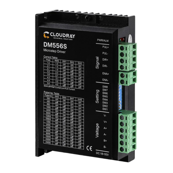
DM556S USER MANUAL 3. Drive Port and Connection 3.1 Port function description Function Grade Definition Remarks Input V+ power supply Power supply input port DC 24~50V Input V- power supply connect two terminals of motor’s phase-B winding Motor connection port connect two terminals of motor’s phase-A winding... -
Page 6: Motor Connection
DM556S USER MANUAL When the stepper motor is working, it also keeps the characteristics of the generator. At deceleration, the kinetic energy accumulated by the load is converted into electric energy, which will be superimposed on the drive circuit and the input power. In application, attention should be paid to the setting of acceleration and deceleration time to prevent the protection of the drive or power supply. -
Page 7: Control Signal Connection
DM556S USER MANUAL speed required. 3.4 Control signal connection 3.4.1 PUL, DIR port: connection for pulse command switch. The signal interface of standard DM series drive is The upper controller can be the pulse signal generating device, such as PLC, MCU, control card and controller. -
Page 8: Control Signal Wiring Example
DM556S USER MANUAL 3.4.3 Control signal wiring example Common anode Common cathode Difference www.cloudratmotor.com... -
Page 9: The Setting Of Current
DM556S USER MANUAL 4.1 The setting of current Peak Current Average Current Remarks 1.4A 1.0A 2.1A 1.5A 2.7A 1.9A Other Current 3.2A 2.3A can be 3.8A 2.7A custom-made. 4.3A 3.1A 4.9A 3.5A 5.6A 4.0A DIP SW1, SW2, SW3 are used to set current which is output from drive to motor. -
Page 10: Half / Full Flow Selection
DM556S USER MANUAL 1600 3200 6400 12800 25600 Other Subdivision can be custom-made 1000 2000 4000 5000 8000 10000 20000 25000 DIP SW5, SW6, SW7, SW8 are used to set the number of pulses required per revolution of the motor. -
Page 11: Common Faults And Troubleshooting
DM556S USER MANUAL One green and five red indicators Encoder phase error 6. Common Faults and Troubleshooting Phenomenon Possible situations Solutions Check the power supply circuit for normal Power indicator is off power supply The motor rotor is locked but the Pulse signal is weak;... -
Page 12: Appendix A. Guarantee Clause
DM556S USER MANUAL burned up Check whether there is any solder ball due to Internal resistance between excessive addition of solder on the wire terminals is too large connections Acceleration and deceleration time is Reduce command acceleration or increase too short...
Need help?
Do you have a question about the DM556S and is the answer not in the manual?
Questions and answers