
Related Manuals for Cloudray DM Series


Summary of Contents for Cloudray DM Series
- Page 1 DM320S USER MANUAL User Manual D M 3 2 0 S DM series Stepper Drive Address: No.10 Huashenmiao,Huashen Technology Park,Yuhuatai District,Nanjing, China 210000 Email: info@cloudray.com Web: www.cloudraymotor.com...
- Page 2 DM320S USER MANUAL Record of Revisions Revision Date Description of Release July 29, 2021 Initial Release...
-
Page 3: Table Of Contents
DM320S USER MANUAL Contents 1. Product Overview ..........................1 Application Environment and Installation ..................2 2.1 Electrical Specifications ......................2 Environmental requirement ....................2 Drive installation dimensions....................3 Drive installation requirements ....................3 Drive Port and Connection ......................4 Port function description ......................4 Power supply input......................... -
Page 4: Product Overview
1. Product Overview Thank you for choosing Cloudray DM series digital stepper drive. DM series stepper drive, which surpasses the performance of common analog stepper drive comprehensively based on the new 32-bit DSP platform developed by TI, and adopting the micro-stepping technology and PID current control algorithm design. -
Page 5: Application Environment And Installation
200K Stepper Pulse Width Direction Setup Time 2000 Input Signal Voltage 2.2 Environmental requirement Item Cloudray DM320S Installation environment Avoid dust, oil and corrosive environment ) Max Vibration 0.5G(4.9m/s 0℃ ~ 45℃ / 90% RH or less (no condensation) Operating temperature/humidity -10℃... -
Page 6: Drive Installation Dimensions
Application Environment and Installation 2.3 Drive installation dimensions 8.25 2.4 Drive installation requirements Please install the drive vertically or horizontally, with its front facing forward, top facing upward to facilitate cooling. During assembly, avoid drillings and other foreign matters falling inside the drive. During assembly, please use M3 screw to fix. -
Page 7: Drive Port And Connection
Drive Port and Connection 3. Drive Port and Connection 3.1 Port function description Function Grade Definition Remarks Input V+ power supply Power supply input port DC 12~36V Input V- power supply connect two terminals of motor’s phase-B winding Motor connection port connect two terminals of motor’s phase-A winding ENA+... -
Page 8: Motor Connection
Drive Port and Connection The work of the drive is to convert the input power supply with high voltage and low current to the low voltage and high current at both terminals of the motor winding.In this case, the current of power supply will be lower than the motor’s. -
Page 9: Control Signal Connection
3.4 Control signal connection 3.4.1 PUL, DIR port: connection for pulse command The signal interface of standard DM series drive is switch. The upper controller can be the pulse signal generating device, such as PLC, MCU, control card and controller. -
Page 10: Ena Port: Used To Enable Or Disable
Drive Port and Connection 3.4.2 ENA port: used to enable or disable When the default optocoupler is off, the driver outputs current to the motor. When the internal optocoupler is turned on, the driver will cut off the current of each phase of the motor to make the motor free. - Page 11 Drive Port and Connection Difference www.cloudraymotor.com...
-
Page 12: Dip Switch Configurations
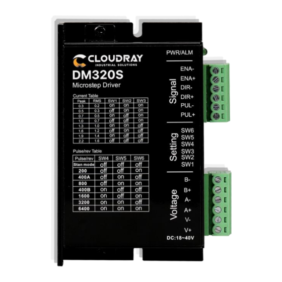
DIP Switch Configurations 4. DIP Switch Configurations 4.1 The setting of current The setting of DIP switches and operating parameters The seting of c urrent Semi / Full current option The setting of pulse per revolution Peak Current Average Current Remarks 0.3A 0.2A... -
Page 13: The Setting Of Pulse Per Revolution
DIP Switch Configurations 4.2 The setting of pulse per revolution Stepping Remarks count/revolution Stan Mode 400A Other Subdivision can be custom-made 400B 1600 3200 6400 DIP SW5, SW6, SW7, SW8 are used to set the number of pulses required per revolution of the motor. -
Page 14: Drive Working Status Led Indication
Drive working status LED indication 5. Drive working status LED indication LED status Drive status Green indicator is flickering Drive working normally One green indicator and one red indicator Drive alarm www.cloudraymotor.com... -
Page 15: Common Faults And Troubleshooting
Common Faults and Troubleshooting 6. Common Faults and Troubleshooting Phenomenon Possible situations Solutions Check the power supply circuit for normal Power indicator is off power supply The motor rotor is locked but the motor Pulse signal is weak; increase the signal does not work current to 7-16mA Motor does not... -
Page 16: Appendix A. Guarantee Clause
Appendix A. Guarantee Clause Appendix A. Guarantee Clause A.1 Warranty period: 12 months We provide quality assurance for one year from the date of delivery and free maintenance service for our products during the warranty period. A.2 Exclude the following: ■...
Need help?
Do you have a question about the DM Series and is the answer not in the manual?
Questions and answers