
Related Manuals for CLIVET ELFOFresh2 CPAN-U 70-120


Summary of Contents for CLIVET ELFOFresh2 CPAN-U 70-120
- Page 1 INSTALLATION AND OPERA- TING MANUAL ELFOFresh CPAN-U 70-500 make up and purification unit with active thermodynamic recovery ELFOFresh 70-120 ELFOFresh 200-500 Change living home 18-09-2019 M05E40C15-06...
- Page 2 Clivet is being working for years to offer systems able to assure the maximum comfort for long time with high reliability, efficiency , quality and safety.
- Page 3 1 - GENERAL It is advisable to read it carefully so you will save time during operations. Follow the indications so you will not cause damages to things and injuries to people Before going ahead with operations, read the GENERAL WARNINGS on page 97 Pay particular attention to : WARNING, identifies particularly important operations or...
- Page 4 TFT90X GPRX DAIR50X - DAIR80X CPRX AIRJET 50/I - 80/l supply diffuser - DN90 round flexible tube (Int. diam. Soundproofed plenum for air Manifold for DN150-200 air white frame and black inside 78mm) in a 20m. coil without insulation recirculation recirculation plenum GAIR50X - GAIR80X IT90X...
- Page 5 BD14CX BD8CX TFPNX RTPTX Grill for recirculation air return plenum 325x175 14-output distribution box, 8-output distribution box, Flat flexible tube 132x52mm Round/flat tube connecting joint mm white DN200 joint DN150-200 joint in a 20m. coil without insulation IT100X Insulation in a 20mt. coil REPPX for flat flexible tube 132x52 Flow controller for flat tube...
- Page 6 Filter Filter only on the intake grille...
- Page 7 Cover the plenum, openings, grilles with cardboard, adhesive tape, etc... Remove caps...
- Page 8 Consider sound emissions CPAN-U 70-120 Avoid installations next to For details see the manual bedrooms sections Respect the spaces to conduct normal and extraordinary maintenance Install in a local or compartment where the temperature can't drop below 0 ° C. Trapdoor opening * extraction air filters from below Aeraulic ducts...
- Page 9 Ceiling access Space to access: If there are electric heaters, CPAN-U 200-500 * 700 - filter access from below, electrical panel on increase access space board unit * 200 - filter access from below, remote electrical panel AE fresh air intake Trapdoor opening ES air expulsion ambient air distribution...
-
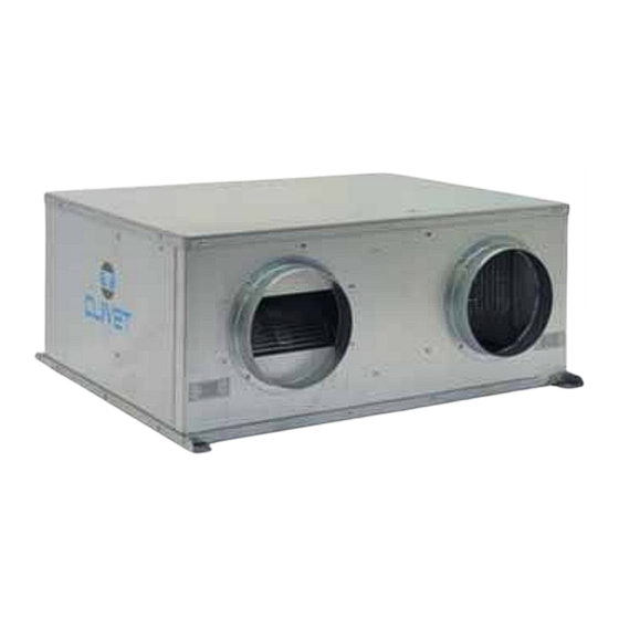
Page 10: Unit Description
1 - GENERAL 1.1 UNIT DESCRIPTION CPAN-U 70 - 120 CPAN-U 200 - 500 1 Serial number label 7 Electrical remote panel It is possible to remove the electrical panel and 2 Exhaust air fan make it remote to facilitate the installation It rejects the unhealthy air outdoors. - Page 11 1 - GENERAL 1.2 ACCESSORIES CDPX : Discharge condensate pump (size 200-500) EHPCX : Preheating elements 0,7 kW in duct (size 70-120) Preheating elements 1,5/3 kW in duct (size 200-500) FSEX : Electronic filter kit (size 70-500) HSE3LX: Immersed electrode steam humidifier for Elfofresh DN200 (size 200-500) HSE3MX: Immersed electrode steam humidifier for Elfofresh DN250 (size 200-500) FAEX : Kit of exhaust air filter (size 200-500) CMMBX : Serial communication module to supervisor (MODBUS)
- Page 12 1 - GENERAL CPAN-U 200 - 500 Ambient exhaust air Grid to prevent small animals or leaves from entering inside (option) Outdoor air intake Kit of electric resistance (option) Remote electrical panel Filter extraction with remote electrical panel Electronic filter (option) Filter extraction with built-in remote electrical panel Kit of exhaust air filter (optional) Ambient air intake...
-
Page 13: Unit Identification
1 - GENERAL 1.3 UNIT IDENTIFICATION PRELIMINARY INFORMATION Before beginning the work, ensure you that have the number Serial label final project for installing the aeraulic, hydraulic, elec- The serial number label is positioned on the unit, tric,drains and positioning the units. generally next to the electrical panel, and allows you to indentify all the unit features. -
Page 14: Delivery Control
2 - RECEPTION 2.1 DELIVERY CONTROL Do not trample Before accepting the delivery you have to check: Do not leave loose packages during the transport that the unit hasn’t been damaged during transport that the materials delivered correspond with that indicated on the transport document comparing the data with the identification label ‘A’... - Page 15 2 - RECEPTION Packing removing Be careful not to damage the unit. Cut the fixing strips. Remove the packaging lifting it upwards. Remove the protective nylon. Keep packing material out of children's reach it may be dangerous. Recycle and dispose of packing material in conformity with local regula- tions.
- Page 16 3 - POSITIONING 3.1 CLEARANCE ACCESS RECOMMENDED The installation has been implemented by qualified technical personnel only and that the instructions con- tained in the present manual and the local regulations in force have been adhered to. Intended use Use the unit for the air treatment. Follow the limits defined in the technical bulletin and on this manual.
- Page 17 3 - POSITIONING CPAN-U 70 - 120 A Distance to prevent vibrations from being transmitted. B Trap door for routine maintenance (access to the connections of the electrical panel, air filters and the optional electronic filter) C Trap door for extraordinary maintenance D Access to the electrical panel E Access to clean the filter (air filters) F Access to conduct extraordinary maintenance (to...
- Page 18 3 - POSITIONING CPAN-U 200 - 500 CPAN-U 200 - 500 A Space to access the electrical panel B Space necessary for the by-pass damper C Distance to prevent vibrations from being transmitted (insert a neoprene sheet) D Trap door for routine maintenance (access to electrical panel and optional electronic filter) E Access to conduct extraordinary maintenance (to replace the fan, compressor, etc.)
- Page 19 3 - POSITIONING 3.2 CEILING POSITIONING 3.3 FLOOR POSITIONING Fix some M8 threaded bars (not supplied) to the Insert the M8 threaded bar on the support base. ceiling. Match the upper hole of the antivibration device Pass the M8 threaded bars in the brackets on the with the hole of the support bracket.
-
Page 20: Electric Panel
3 - POSITIONING 3.4 ELECTRIC PANEL CPAN-U 70 - 120 CPAN-U 200 - 500 The electrical panel is provided assembled on the unit side but if necessary it can be remotely controlled up to 2 mt. away. Access to the electrical panel: from below Remote positioning lateral... -
Page 21: Access To Internal Parts
3 - POSITIONING 3.5 ACCESS TO INTERNAL PARTS CPAN-U 200 - 500 CPAN-U 70 - 120 Access from the upper side Access from the upper side Access from the bottom side... -
Page 22: Ambient Thermostat
3 - POSITIONING 3.6 AMBIENT THERMOSTAT The choice of the installation point is decisive for the environmental comfort and the energy consumption. The thermostat must be placed : In a room with medium temperature and humidity conditions, representative of the other rooms at a height of 150 cm preferably on an internal wall Positions to avoid :... -
Page 23: Water Connections
4 - WATER CONNECTIONS 4.1 CONDENSATE DISCHARGE CPAN-U 200 - 500 The condensate must be disposed in order to avoid damages to people and things. Unit discharge fitting: the connection must not transmit mechanical stresses and must be performed taking care not to damage the unit discharge fitting. -
Page 24: Aeraulic Connections
(not provided by Clivet), so as to prevent water from entering. During the design stage, their features must limit load losses so as not to affect the correct operation of the unit. - Page 25 (size 200-500) B. Avoid compressing the pipes and tight bends to prevent any pressure drop. The flexible pipe supplied by Clivet allows bends of 180° to be made without any compression and without any reduction in pressure drop...
- Page 26 5 - AERAULIC CONNECTIONS 1 - Introduce the perforated aluminium part The ducts should not be tilted towards unit to avoid the condensate and water return. 2 - Pull the polyester part down (plastic) Insulated ducts A - Flexible pipe fixing 3 - Tighten well using the strap Layers of the flexible pipe Sheath...
- Page 27 5 - AERAULIC CONNECTIONS 5 - Pull the sheath down AIRJET supply diffuser + extraction valve The extraction valve must not be positioned on the side facing the air supply. 6 - Tighten well using the strap Air distribution valve (VIEX) The air distribution valve must not be positioned above the bed, for example.
- Page 28 5 - AERAULIC CONNECTIONS 5.4 AERAULIC SYSTEM Before installing the aeraulic system, check the passages of the pipes and position of the accessories based on the design. Unit position: in a specific room (where temperature never drops below 0°C), away from bedrooms. Check useful height available in relation to the unit’s height and local regulatory constraints.
-
Page 29: Electric Connections
6 - ELECTRIC CONNECTIONS 6.1 ELECTRICAL CONNECTION DIAGRAM All electrical operations should be performed by trained personnel having the necessary requirements by the regulations in force and being informed about the risks relevant to these activities. This unit is required reliable earthing The unit must be installed with an Creepage Breaker near the power supply and must be effectively before usage, otherwise might cause earthed. -
Page 30: Remote Controls
6 - ELECTRIC CONNECTIONS 6.2 ELECTRICAL CONNECTION DIAGRAM CPAN-U 70 - 120 A - Remote control (costumer use ) B - 230/1/50 power supplì Provide the power outlet ( on/off switch + schuko) C - Electric heater D - Electrical panel REMOTE CONTROLS Refer to the unit electrical diagram (the number of the diagram is shown on the serial number label). - Page 31 6 - ELECTRIC CONNECTIONS Remote summer-winter selector switch (heat/cool) HID-P1 AMBIENT THERMOSTAT It allows the change of the operating mode from heating to cooling from an external control. Compulsory with humidifier option or if the Set parameter 161 ELFOCONTROL not present = 0 only from keypad/thermostat Connect the HID-P1 ambient thermostat as indicated in = 1 control only from remote control...
-
Page 32: Power Supply
6 - ELECTRIC CONNECTIONS REMOTE ELECTRIC PANEL - CPAN-U 200 - 500 Remote control inputs Fastening holes of the eletric panel Main control module Relay KAfiltr. Expansion module Aux. circuit transformer AP exp Compressor fuse RS485 Serial communication module 230v auxiliary circuit protection fuse Connection of the service keypad FU 12v Protection fuse 12v (AP1) 5x20 T 160mA... - Page 33 6 - ELECTRIC CONNECTIONS REMOTE CONTROLS Refer to the unit electrical diagram (the number of the diagram is shown on the serial number label). Remove the jumper (P) on the terminal block if the control is used The control connect HUMIDIFIER OPTION Silent Remote summer-winter selector switch (heat/cool)
- Page 34 6 - ELECTRIC CONNECTIONS Fire signalling (alarm AI) HID-Ti5 - REMOTE CONTROL WITH TOUCH SCREEN DISPLAY, FOR BUILT-IN INSTALLATION (BOX 503) OR In case of alarm signalling from a fire surveying station, FOR WALL INSTALLATION.(option) the unit can put the ambient: Remote user keypad, to control the unit main functions.
- Page 35 7 - START-UP 7.1 PRELIMINARY INFORMATION ducting are completed, connected and without obstructions General Grilles, outlets, and diffusers must be free of The indicated operations should be done by obstructions (furniture, shelves, etc.), open and pre- qualified technician with specific training on the calibrated, so as to ensure proper air distribution, product.
-
Page 36: Preliminary Checks
7 - START-UP PRELIMINARY CHECKS The indicated operations should be done by qualified technician with specific training on the product. Upon request, the service centres performing the start-up. The electrical, water connections and the other system works are by the installer. Agree upon in advance the star-up data with the service centre. -
Page 37: Start-Up Sequence
7 - START-UP START-UP SEQUENCE During the initial start-up procedure, the fan airflow rates must be adjusted in order to balance the amount of air entering and exiting the environment. Door and windows must be mounted. External doors and windows must be closed. Instruments needed in addition to normal instruments. - Page 38 7 - START-UP Adjustable vents VIEX - Extraction/intake valve Closed GQIEX - Extraction/intake squared grille 1 - Unhook 2 - Remove 3 - Overturn 6 - Rotate 4 - Extract 5 - Remove rubber PAIR50X/80X - Suction/supply plenum with control damper 1 - Closed 2 - Adjust with screwdriver...
- Page 39 7 - START-UP START-UP SEQUENCE START-UP SEQUENCE Pag. HEATER OPERATION CHECK (option) set the unit to heating mode temporarily set parameter 208=1 with the unit not powered, open the compressor's fuse holder (FU1 to sizes 200-500 / FUG to sizes 70-120) 29/32 start the unit and wait until the heaters begin treating the supply air with the unit not powered, set parameter 208=0...
-
Page 40: Airflow Tables
7 - START-UP AIRFLOW TABLES Airflows measured on the external inlets/outlets. Example of conduits: circular tube airflow speed medium rectangular tube airflow speed medium Ø mm (LxH) 1,59 1,62 1,10 1,08 0,62 0,78 2,72 2,60 1,89 1,85 1,06 1,11 2,76 2,78 1,77 1,85... -
Page 41: Parameter Modification
7 - START-UP 7.2 FAN CONFIGURATION - CPAN-U 200 - 500 Depending on the ducting pressure drops are available three configurations that can be set by the ambient thermostat through the parameter modification. The setting must be performed both for the exhaust fan and for the supply fan. -
Page 42: Return Air
7 - START-UP 5. RETURN AIR If the return air flow is high: If the return air flow is low: set P01 = 2 set P01 = 2 If it is still high: If it is still low: set P01 = 1 set P01 = 3 If it is still high: If it is still low:... -
Page 43: Start-Up Report
7 - START-UP CHECK OF THE AIR FLOW CPAN-U 70-120 The unit automatically configures the flow rate based on the system’s load losses. If needed, you can take action as indicated. RETURN AIR If the return air flow is high: If the return air flow is low: decrease the value of the parameters increase the value of the parameters... -
Page 44: Keys Functions
8 - CONTROL KEYS FUNCTIONS Ambient setpoint control up / down Ventilation Alarm Eco (used in combination with other keys) Cooling / Heating Clean ON / OFF KEYS COMBINATION It displays the temperature detected in ambient Long press It scrolls down the alarm list of one code at a time Single press Alarm reset in progress Long press... -
Page 45: First Start-Up
8 - CONTROL 8.1 FIRST START-UP Position the main switch of the installation on “On ”. The display is switched on in Off. 21.0 Hold the On-Off button ( I ) for 5 seconds until the unit start-up. The ambient setpoint is displayed. Select the desired operating mode between heating and cooling Ventilation only... -
Page 46: Other Configurations
If no action is performed, after 10 seconds the thermostat will exit from the scheduling mode thermostat temperature probe offset thermostat humidity probe offset Clivet Bus thermostat address A Ambient setpoint control button up B Ambient setpoint control button down On - Off... -
Page 47: Main Functions
8 - CONTROL 8.5 MAIN FUNCTIONS Winter HR control ELFOFresh treats fresh air: it is used for the air Only if is present the humidifier option. filtration, humidification or dehumidification and the The humidification is enabled only in heating. right temperature is reached to guarantee always fresh The set point can be modified by thermostat with the and clean air in the served rooms. - Page 48 8 - CONTROL 8.6 VENTILATION AIR FLOW MODULATION REDUCED FLOW IN WINTER With an outdoor air temperature lower than -5°C, the flow is reduced (A) to maintain the ambient inlet air temperature (I) approximately equal to the internal temperature ( 20°C) . In this situation the need of ventilation is completely satisfied NOMINAL FLOW...
- Page 49 8 - CONTROL 8.7 ALARMS Whenever the unit is in alarm, on the thermostat display is visualized the code of the alarm in progress. The code will alternate at intervals of about 3 seconds with the display of the ambient temperature. In case of multiple alarms will be displayed what occurred first.
- Page 50 8 - CONTROL ALARMS Alarm Description Possible cause No communication between thermostat and unit Check wiring between the thermostat and the unit board Loose wiring, possible failure of the board or the thermostat following an anomaly related to the power supply voltage Inlet temp.
- Page 51 8 - CONTROL ALARMS Alarm Description Possible cause Outlet low temp. signaling the temperature of the air supplied in the room is too low; - the air is not compatible with the unit's operating limits - insufficient supply air flow rate in ambient - filters air dirty - obstacles air distribution system - supply fan fault...
- Page 52 8 - CONTROL ALARMS Alarm Description Possible cause Modulating resi stance On with recovery circuit Air preheating, no anomaly Control of the supply title not satisfied The unit operates regularly. High supply air humidity: open windows, lots of people, etc. Inconsistency of the temperature differential The temperature difference at the air inlet and outlet is not consistent with the mode.
- Page 53 8 - CONTROL 8.8 - HID-Ti5 / REMOTE CONTROL WITH TOUCH SCREEN DISPLAY, FOR BUILT-IN INSTALLATION (BOX 503) OR FOR WALL INSTALLATION (OPTION) Signal led Reset Restart of the device Diagnostics Temperature and humidity probe Display 28.3 °C 11:15 Outside temperature Hour 26.2 °C Ambient Temperature...
- Page 54 8 - CONTROL Access functions Impostazioni Press Settings Lock touch (press) Time scheduling Lock the display for 20 sec. for the thermostat cleaning Display automatic shutdown Prolonged press 5 seconds = access parameters Brightness (installer use) Beep ((touch sound) Press = access unit stata (Visualization only) Home page (not used) Previous menu Down / Value decreasing...
- Page 55 8 - CONTROL SETPOINT AMBIENT It allows the setting of the desired room temperature, the current mode. Setpoint Setpoint Setpoint Riscaldamento Riscaldamento Riscaldamento 17.0°C 17.0°C 21.0°C Raffrescamento Raffrescamento Raffrescamento Press Select: Press Press to increase or riscaldamento decrease the value (heating) Setpoint Setpoint...
-
Page 56: Time Scheduling
8 - CONTROL TIME SCHEDULING It allows the user to customise the time scheduling of the days, according to his/her own requirements, setting up to 6 different time bands for each day and selecting the relative setpoint temperature. Impostazioni Schedulatore Lunedì... - Page 57 8 - CONTROL VISUALISATION ALARMS LOG/ RESET Visualisation the symbol Before resetting an alarm identify and remove the cause that generate it Repeated reset can cause irreversibile damages as malfunctioning of the system itself. In case of doubt please contact an Assistance Centre. Evento Evento Evento...
-
Page 58: Advanced Configurations
8 - CONTROL 8.9 SERVICE KEYPAD - OPTION The service keypad allows the access to the unit parameters to perform the advanced settings or to display the operating stata. For the normal use of the keypad is not necessary the access to the unit parameters. The operations listed below are required only for particular calibrations and configurations, they are therefore addressed only to qualified authorized assistance centres. - Page 59 8 - CONTROL Parametres Mnemonico Description default Parameters protected by password Outdoor temperature 0 Text0 Press the Set button ( L ) to enter in the scheduling mode. Outdoor temperature 1 Text1 Text2 Outdoor temperature 2 Position on index 0 using the M and O arrows. Outdoor temperature 3 Text3 Insert the password 115 by the index Increment...
- Page 60 8 - CONTROL 8.10 UNIT STATA Index Description Unit of measurment Outlet actual SetPoint °C Inlet actual SetPoint °C Inlet temperature °C External temperature °C VHeat/CoolExt control component VHeat/CoolAmb control component VHeat/CoolRec control component Compressor inverter control signal Compressor operating mode (1= heat pump) 0 ÷...
- Page 61 The access to parameters or modifications are allowed only to the installer who assumes all responsibility, in case of doubts please contact Clivet. For any changes not permitted or not approved by Clivet, the same declines any responsibility for malfunctions and/or damages to the unit/system.
- Page 62 8 - CONTROL Minfiltri Filter min. control signal value SetAlarmFreeze SetPoint for water coil antifreeze alarm °C DeltaAlarmFreeze Differential for the water coil antifreeze alarm reset °C Tstarting Min. interval between start/stop of two compressors FanPFcorr PWM fan power factor correction 1=500ns SetURCool UR SetPoint in cooling...
- Page 63 8 - CONTROL DeltaTThrowCool Differential for the MaxTThrowCool calculation °C MinTThrowCool Min. supply temperature in Cool °C MinSetTHeat Min. ambient set that can be set manually in Heat °C MaxSetTHeat Max. ambient set that can be set manually in Heat °C MinSetTCool Min.
-
Page 64: Maintenance
9 - MAINTENANCE 9.1 GENERAL 9.4 PUT AT REST If a long period of inactivity is foreseen: Maintenance must be done by authorized centres or by qualified personnel put the unit in OFF The maintenance allows to: wait a few minutes to allow all the actuators to maintain the unit efficiency reach the rest position reduce the deterioration speed to whom every... -
Page 65: Air Filter
9 - MAINTENANCE 9.8 AIR FILTER CPAN-U 70 - 120 It is very important for the air treatment coil to be able to offer maximum thermal exchange. Therefore, the unit must always operate with the filters installed and clean. Cleaning and replacement of filters are very important in terms of health and hygiene. - Page 66 9 - MAINTENANCE 9.9 FESX - ELECTRONIC FILTER - OPTION Switch off the unit. CPAN-U 70 - 120 Access to the filter The access to the filter is possible in two positions : 1 - Superior access (floor units) 2 - Lower access (ceiling units) To access to the filter: Remove the closing panel (A) Remove filter support (B)
- Page 67 9 - MAINTENANCE 7. Leave the electrostatic cells to dry in a hot room or directly Quick connector closed (F) in the sun for a few hours. Keep the cells lifted from the ground using two metal or wooden laths. 8.
- Page 68 9 - MAINTENANCE 9.10 RETURN / SUPPLY AMBIENT FILTER 9.11 FAEX - KIT EXAUST AIR FILTER - OPTION CPAN-U 70 - 120 CPAN-U 200 - 500 The ambient filter installation is possible in 3 positions: The ambient filter installation is possible in 2 positions: A - from the top (floor units) A - from the top (floor units) B - from the bottom (ceiling units)
-
Page 69: Periodic Checks
9 - MAINTENANCE 9.12 FANS CPAN-U 70 - 120 CPAN-U 200 - 500 The fans can be removed from above and from below. The fans can be removed from above. Remove the roof or the lower panel. Remove the roof Unscrew the 4 front screws. - Page 70 9 - MAINTENANCE Before putting it back in place: Drainage of humidifier cylinder The cylinder must be drained in these situations: The filter body does not need to be replaced. Wash it with water and place it on the new cleaning of the cylinder cylinder, using the new gasket that comes with it.
- Page 71 9 - MAINTENANCE RECOMMENDED PERIODICAL CHECKS SHEET 9.14 Checks carried out on……………………..by……………………………...………….company…....……………………………………………. intervention frequency (months) presence corrosion panel fixing fans fixing coil cleaning bowl cleaning + sanitisation outflow test electrostatic filter cleaning/inspection electronic filter cleaning/inspection air flow rate measurement channelling: anti-vibration devices and fastenings check power supply cable isolation and fastening check earth cable check electric control board cleaning...
-
Page 72: Technical Information
10 - TECHNICAL INFORMATION 10.1 DIMENSIONS Size 70-120 ** MINIMUM SPACE FOR MAINTENANCE A(15) : only for ceiling installation (1) REMOVABLE PANEL FROM LOWER ACCESS OF THE EXHAUST AIR FILTER (AE) FRESH AIR INTAKE (2) REMOVABLE PANEL FROM LOWER ACCESS OF THE ELECTRICAL PANEL (ES) AIR EXHAUST (3) REMOVABLE PANEL FROM LOWER ACCESS OF THE HANDLING FILTER AIR (M) AMBIENT AIR DISTRIBUTION... - Page 73 10 - TECHNICAL INFORMATION Size 200-300 ** min: a) - ceiling installation, filter access from below, remote electrical control board at a distance of at least 200 mm b) -ceiling installation, filter access from below, non-remote electrical control board at a distance of at least 700 mm c) -floor installation, lateral filter access, remote electrical control board at a distance of at least 400 mm d) -floor installation, lateral filter access, non-remote electrical...
- Page 74 10 - TECHNICAL INFORMATION Size 500 ** min: a) - ceiling installation, filter access from below, remote electrical control board at a distance of at least 200 mm b) -ceiling installation, filter access from below, non-remote electrical control board at a distance of at least 700 mm c) -floor installation, lateral filter access, remote electrical control board at a distance of at least 400 mm d) -floor installation, lateral filter access, non-remote electrical...
-
Page 75: General Technical Data
10 - TECHNICAL INFORMATION 10.2 GENERAL TECHNICAL DATA SIZES COOLING AE 30°C Cooling capacity 0,429 0,813 1,57 2,10 3,01 Compressor power input 0,164 0,279 0,498 0,640 0,916 Total power input 0,189 0,315 0,542 0,700 1,04 2,27 2,58 2,90 3,00 2,91 COOLING AE 35°C Cooling capacity 0,446... -
Page 76: Sound Levels
10 - TECHNICAL INFORMATION 10.4 SOUND LEVELS Sound levels refer to the unit at full load installed on the ceiling, Sound Power Level (dB) Sound ducted, with nominal fan air flow rate. Available static pressure 40 Sound pressure Power Level level Octave band (Hz) In accordance with the UNI-EN ISO 3744 regulation, the average... - Page 77 11 - OPTION 11.1 EHPCX : PREHEATING ELEMENTS 0,7 KW CPAN-U 70 - 120 Resistances : front view Install the resistances (A) on the fresh air return. Install an air filter upstream (B). This should be at least a G2 class filter to protect the heating elements (provided by the customer) L = 1,5 mt max.
- Page 78 11 - OPTION Remove the jumper P on the XC terminal block of In case of installation of the resistance module it is necessary to move the air probe present in the unit. the unit electrical panel. Disconnect the probe connector. Disassemble the return air (1) probe from the unit.
- Page 79 11 - OPTION 11.2 EHPCX - PREHEATING ELEMENTS 1,5/3 KW CPAN-U 200 - 500 Resistances : side view Install the resistances (A) on the fresh air return. Install an air filter upstream (B). This should be at least a G2 class filter to protect the heating elements (provided by the customer) L = 1,5 mt max.
- Page 80 11 - OPTION Remove the jumper P on the X1 terminal block of In case of installation of the resistance module it is necessary to move the air probe present in the unit. the unit electrical panel. Disconnect the probe connector. Disassemble the return air (1) probe from the unit.
- Page 81 11 - OPTION 11.3 HSE3LX - IMMERSED ELECTRODE HUMIDIFIER DN200 (gr.200-500) HSE3MX - IMMERSED ELECTRODE HUMIDIFIER DN250 (gr.200-500) A shut-off valve installed on the humidifier inputs CPAN-U 200 - 500 allows the maintenance operations without draining the system. The humidifier is supplied separately from the unit. A filter must be installed on the humidifier supply It must be installed on the supply duct, connected duct.
- Page 82 11 - OPTION Limit values for the supply water with medium-high conductivity Humidifier electrical panel in an immersed electrode humidifier Hydrogen ions Specific conductivity at 20°C S/cm 1250 Total dissolved solids mg/l Dry residue at 180°C mg/l Total hardness mg/l CaCO Temporary hardness mg/l CaCO Iron + Manganese...
- Page 83 11 - OPTION ALARMS- RED LED LED flashes: Duration seconds Rapid flashes 0,2 seconds Long flashes 1 second LED flashes Description - causes Solution Action 2 rapid Excess electrode current: 1 - The water conductivity must be between 75 and1250 S/cm. humidif.
- Page 84 11 - OPTION ALARMS- RED LED LED flashes Description - causes Solution Action 2 long serial disconnected 1 - check the connection of electricity and their supervisor humidif. 1 - Cable broken /disconnected / stopped not properly connected after the previous set 3 long No supply water: the humidifier...
- Page 85 11 - OPTION ALARMS- RED LED LED flashes Description - causes Solution Action 7 long External control signal not 1 - Check and connect correctly. humidif. connected correctly (2-10V only); 2 - Set A0 =1; based on external signal set A2 = 0: 0-1V, stopped or - for control via serial (variable A2=1 0-10V, A2=2 2-10V, A2=3 0-20mA, A2=4 4-20mA...
- Page 86 11 - OPTION 11.4 CDPX - DISCHARGE CONDENSATE PUMP Centrifugal condensate discharge pump that guarantees an optimal condensate downflow everytime it is not possible to have a proper downflow by gravity. The packaged structure includes a floating chambre with two levels of intervention: the first level starts up itself the pump while the second level is a safety level that intervenes in case of difficulty of the pump in the downflow stopping the unit CPAN-U 70 - 120...
- Page 87 11 - OPTION Ø int. 6 mm ID Insert vent pipe (D) and insert it Connect the condensate discharge pipe (H) to a drainage network. in the appropriate cable gland (G) Connect the pipe (E) to pump Do not crush the pipe that could limit the passage of water Fix with the hose clamps (F) Table flow-rare (l/h) Electrical connection...
- Page 88 11 - OPTION CPAN-U 200 - 500 Used components Unused components Air intake Discharge pipe Corrugated pipe Fairlead Vent pipe Cable wired 90° curve Pump Viti (2) Bracket support Antivibration support Rubber pipe 50 mm Hose clamps (2) To access remove the higher or lower panel Insert vent pipe (B) Remove the discharge condensate pipe (C) + clip Remove the standard condensate drain pipe (A)
- Page 89 11 - OPTION Ø int. 6 mm ID Connect the condensate discharge pipe (G) to a drainage network. Fix with the hose clamps (I) Do not crush the pipe that could limit the passage of water Table flow-rare (l/h) Electrical connection Total tube length (ø...
- Page 90 11 - OPTION 11.5 FAEX - KIT OF EXHAUST AIR FILTER Lateral ceiling installation not allowed. CPAN-U 200 - 500 The ambient filter installation is possible in 3 positions: A - from the top (floor units) B - from the bottom (ceiling units) C - lateral (floor units) Minimum space for filter extraction.
- Page 91 11 - OPTION 11.5 FESX - ELECTRONIC FILTER The most common contaminants for which the filter is CPAN-U 200 - 500 designed are : air pollution by PM10, PM 2,5 and PM1 Contaminants that can be filtered: dry smokes powder (up to 0.3 microns) smoke electrostatically charged Contaminants that can NOT be filtered: water vapours also in low concentration...
-
Page 92: Green Led
11 - OPTION 11.7 CMMBX : SERIAL COMMUNICATION MODULE TO ELECTRIC PANEL - CPAN-U 70 - 120 SUPERVISOR (MODBUS) The unit can be connected to ELFOControl , remote keypad (HID-Ti5 ) or an external supervisor system. * parameter description Extended description value Adress ModBus supervision serial... -
Page 93: Modbus Protocol
11 - OPTION 11.8 MODBUS PROTOCOL STATUSES, PROBES, ALARMS, CONTROLS CONVENTIONAL CODES FOR THE PROBES STATUS AREA Error on one of the probes (value higher than the expected operating range). This is indicated with the Modbus rd: read specific probe error code = 0x7fff. Address wr: write (decimal) - Page 94 11 - OPTION (1) The configuration alarm is sent when at least one of Bitmap 2 alarmas the conditions below has occurred: Posit. meaning mask the PotC1 =0 parameter is set; when the H2OLogic=3 parameter is set to bit0 High pressure alarm 0x01 PotC2 >= PotC1;...
- Page 95 11 - OPTION SUPERVISOR AREA Simplified table Address rd: read Value to Modbus wr: write send (decimal) 2101 rd/wr Flag register bitmap Weight EXTERNAL value of the Vrec 2102 rd/wr Controls adjustment component Unit switching Return temperature EXTERNAL on and/or go 2103 rd/wr °C/10...
- Page 96 11 - OPTION REFERENCE CONTROLS FOR PROBES AND OTHER PARAMETRES SPECIAL CONTROLS Modbus address of a generic parameter = 1000 + key- There is the option of setting the adjustment board display index – 1. component of the compressors and/or specific adjustment probes or the Silent Mode control of the PARAMETERS AREA fans via the Modbus serial device.
-
Page 97: General Instructions
12 - GENERAL INSTRUCTIONS 12.1 MANUAL 12.3 ELECTRIC SYSTEM The manual allows a correct unit installation, use and maintenance. Pay particular attention to : This unit is required reliable earthing WARNING, identifies particularly important operations or before usage, otherwise might cause information death or injury. -
Page 98: User Training
12 - GENERAL INSTRUCTIONS electromagnetic interferences. Do not lay the cables parallel to other cables; cable crossings are possible, only if laid at 90°. Connect the screen to the ground, only if there aren’t disturbances . Guarantee the continuity of the screen for the entire extension of the cable. -
Page 99: Residual Risks
13 - RESIDUAL RISKS the circuit parts that remain isolated by the closure of the tap. General Do not remain in the vicinity of the safety valve and never leave the In this section the most common situations are signalled. As these refrigerating system taps closed. -
Page 100: Dismantling And Disposal
14 - DECOMMISSIONING 14.1 DISCONNECTION If disposal takes places at the same time as delivery of a new electrical or electronic equipment for the same family, the Only authorised personnel must disconnect the unit. product may be collected directly by the distributor. Avoid leak or spills into the served area. - Page 101 USER MANUAL ELFOFresh 70-120 ELFOFresh 200-500 Change living home...
- Page 102 15 - USER MANUAL 15.1 USER Note the unit lable data so you can provide them at the It is forbidden the use of the device to children and assistance centre in case of intervention (see "Unit unassisted disables . identification"...
- Page 103 15 - USER MANUAL CPAN-U 70 - 120 Grid to prevent small animals or leaves from entering Intake air filter inside (option) Electronic filter (optional) Kit of electric resistance (option) Exhaust air filter Unit Condensate discharge Elfocontrol (option) HID-Ti5 Remote control (option) G Ambient thermostat Power supply On the RS485 board is possible to connect only one control,Elfocontrol...
- Page 104 15 - USER MANUAL CPAN-U 200 - 500 Grid to prevent small animals or leaves from entering 1. Electronic filter (option) inside (option) 2. Kit of exhaust air filter (optional - recommended) Kit of electric resistance (option) Unit Humidifier kit (optional) Water supply Condensate discharge G Elfocontrol...
- Page 105 15 - USER MANUAL 15.3 VENTILATION AIR FLOW MODULATION REDUCED FLOW IN WINTER With an outdoor air temperature lower than -5°C, the flow is reduced (A) to maintain the ambient inlet air temperature (I) approximately equal to the internal temperature ( 20°C) . In this situation the need of ventilation is completely satisfied NOMINAL FLOW...
- Page 106 15 - USER MANUAL KEYS FUNCTIONS Ambient setpoint control up / down Ventilation Alarm Eco (used in combination with other keys) Cooling / Heating Clean ON / OFF KEYS COMBINATION It displays the temperature detected in ambient Long press It scrolls down the alarm list of one code at a time Single press Alarm reset in progress Long press...
-
Page 107: Ventilation Only
15 - USER MANUAL START UP The display is switched on in Off. Hold the On-Off button for 5 seconds until the unit start-up. The ambient setpoint is displayed Select the desired operating mode between heating and cooling COOLING Hold the Cooling button for 5 seconds until is displayed the Cooling symbol Use the setpoint Control buttons to set the desired setpoint. -
Page 108: Set-Point Control
15 - USER MANUAL SET-POINT CONTROL Use the buttons for the setpoint Control to modify the value. ALARM VISUALIZATION To display all alarms in progress, press the Alarm button. To scroll down the alarm list press repeatedly the Alarm button. The display will return to normal visualization after 5 seconds from the last pressure on Alarms ALARM RESET... - Page 109 15 - USER MANUAL STOP FOR LONG PERIODS Hold the On-Off button for 5 seconds until the unit shutdown. “Off” is displayed ”. Position the main installation switch on “Off”. At the next starting, the unit is started-up in the last set mode.
-
Page 110: Access To The Unit
15 - USER MANUAL MAINTENANCE ACCESS TO THE UNIT CPAN-U 70 - 120 The ambient filter installation is possible in 2 positions: To conduct periodical maintenance, you need to be able to access the unit safely, see the recommended A - from the top (floor units) distances on page 17 and 18 B - from the bottom (ceiling units) Any furniture or other objects must be easily moved. - Page 111 15 - USER MANUAL MAINTENANCE Filters and inlets/outlets must be cleaned to ensure optimal operation of the system. Visually inspect the level of clogging. The device should be visually inspected frequently and cleaned at least every 6 months. CLEANING Check the filter: replace if very dirty or wash it with water To clean: clean in tepid water with common detergent.
-
Page 112: Periodic Maintenance
15 - USER MANUAL MAINTENANCE into the room will be cleaner, thus resulting in cleaner Extraction grille regenerable filter (GAIR50/80X) conduits within Elfofresch Disconnect the conduits from the unit Remove the grille Check for air filters on vents/inlet grilles before switching on the unit, otherwise the entire air distribution system may become dirty. - Page 113 NOTE...
- Page 114 NOTE...
- Page 115 INDEX General Reception Positioning Water connections Aeraulic connections Electric connections Start-up Control Maintenance Technical information Option General instructions Residual risks Decommissioning User manual The data contained in this manual is not binding and may be changed by the manufacturer without prior notice.
- Page 116 Tel. +34 91 6658280 - Fax +34 91 6657806 - info@clivet.es CLIVET GmbH Hummelsbütteler Steindamm 84, 22851 Norderstedt - Germany Tel. + 49 (0) 40 32 59 57-0 - Fax + 49 (0) 40 32 59 57-194 - info.de@clivet.com CLIVET RUSSIA Elektrozavodskaya st. 24, office 509 - 107023, Moscow, Russia Tel.
Need help?
Do you have a question about the ELFOFresh2 CPAN-U 70-120 and is the answer not in the manual?
Questions and answers