
Related Manuals for Keysight APS-M1010

Summary of Contents for Keysight APS-M1010
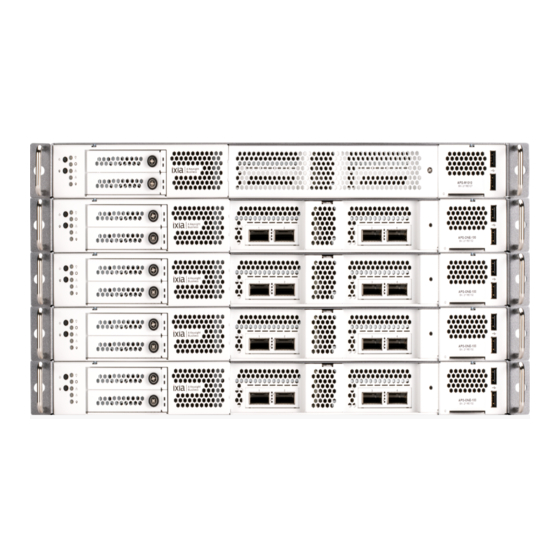
- Page 1 APS-M1010/APS-ONE-100 Platform for IxLoad Release 9.45 Installation Guide 202310131234-07:00...
- Page 2 EULA shall apply, except to the extent that and fitness for a particular purpose. those terms, rights, or licenses are explicitly Keysight shall not be liable for errors or for required from all providers of commercial incidental or consequential damages in con-...
-
Page 3: Contacting Us
APS-M1010/APS-ONE-100 Platform for IxLoad Contacting Us Keysight headquarters 1400 Fountaingrove Parkway Santa Rosa, CA 95403-1738 www.ixiacom.com/contact/info Support Global Support +1 818 595 2599 support@ixiacom.com Regional and local support contacts: APAC Support +91 80 4939 6410 support@ixiacom.com Australia +61-742434942 support@ixiacom.com EMEA Support +40 21 301 5699 support-emea@ixiacom.com... -
Page 4: Table Of Contents
APS-M1010/APS-ONE-100 Platform for IxLoad Table of Contents Contacting Us Chapter 1 Product overview Chapter 2 Functionality overview Rack mounting Aggregation modes Chapter 3 Port aggregation Mode 1 - Aggregated mode (default mode) Mode 2 – Non-Aggregated mode How to configure the Aggregation mode... - Page 5 Appendix C KCOS Compute Node reboot (card hot swap) Index – 5 –...
-
Page 6: Chapter 1 Product Overview
(DUTs). Compute nodes must have a functional management node to operate. Keysight Cluster Operating System (KCOS) is the base operating system. It provides a command line interface (CLI) and a command shell to enable user control of the various services. -
Page 7: Chapter 2 Functionality Overview
This chapter provides a functional overview of the APS-M1010/APS-ONE-100 Platform for IxLoad. The entire system runs on the Keysight Cluster Operating System (KCOS). To perform any system- level operation, you will need to use KCOS CLI commands (see the APS-100/400GE Series Plaform, KCOS Command Line Interface (CLI), For IxLoad Release 9.45, CLI Reference Guide). - Page 8 Chapter 2 Functionality overview Compute Nodes: The second and third blocks in the diagram represent Compute Nodes. The Compute Nodes are used for generating custom traffic. They have interfaces for connecting devices under test (DUTs). The "TestPorts" shown in the preceding diagram are displayed as Ports in the IxLoad GUI.
-
Page 9: Rack Mounting
Make sure the cabling is positioned away from equipment that can damage the cables. Operating environment is within the ranges listed in the data sheet and installation guide. Make sure airflow around the APS-M1010/APS-ONE-100 and respective vents is unrestricted. To rack mount the APS-M1010/APS-ONE-100 chassis: 1. - Page 10 Chapter 2 Functionality overview 5. Continue installing the outer rail bracket to the mounting frame. Attach the outer rail assembling to the frame and press the bracket to form a rack on both ends. Repeat to fully mount the bracket assembly on the other side. –...
- Page 11 Chapter 2 Functionality overview 6. Pull out the middle channel until the ball bearing retainer is locked forward. Verify ball bearing retainer is locked forward. – 11 –...
- Page 12 Chapter 2 Functionality overview 7. Slide the release tab and push barebone into rack. Make sure the barebone is completely installed onto the rack. 8. Repeat this procedure until all components are rack mounted. – 12 –...
-
Page 13: Aggregation Modes
Chapter 2 Functionality overview Aggregation modes IxLoad on the M1010/APS-ONE-100 Platform supports two modes: Mode 1 - Aggregated Mode (default mode) Mode 2 - Non-Aggregated Mode Switching between aggregation modes is not recommended at this time. This functionality will be supported in a future release. Mode 1 - Aggregated mode (default mode) Aggregated mode is the default mode. - Page 14 Chapter 2 Functionality overview The preceding diagram is an example of one of the supported TestPort-to- physical-port configurations. TestPort-1 could be mapped to Port-2, TestPort-2 could be mapped to Port-4, etc. – 14 –...
-
Page 15: Chapter 3 Port Aggregation
APS-M1010/APS-ONE-100 Platform for IxLoad HAPTER Port aggregation IxLoad on the M1010/APS-ONE-100 Platform supports an Aggregated Mode (default mode) and a Non-Aggregated mode. Aggregated Mode (default mode) Non-Aggregated Mode How to configure the Aggregation mode Mode 1 - Aggregated mode (default mode) Aggregated mode is the default mode. -
Page 16: Mode 2 - Non-Aggregated Mode
Chapter 3 Port aggregation Mode 2 – Non-Aggregated mode In this mode: Each TestPort needs to be mapped to an individual physical Port TestPorts can be assigned to different NetTraffics The preceding diagram is an example of one of the supported TestPort-to- physical-port configurations. -
Page 17: How To Configure The Aggregation Mode
Chapter 3 Port aggregation How to configure the Aggregation mode In the IxLoad UI, you use use a card's context menu to select the aggregation mode as shown in the following image. In Aggregated mode, you cannot select an individual TestPort. When TestPort 1 is selected, TestPort-2 will automatically be selected. -
Page 18: Chapter 4 Related Documentation
APS-M1010/APS-ONE-100 Platform for IxLoad HAPTER Related documentation The latest documentation for each release can be found on the Ixia Support website. Documentation Description APS-M1010/APS-ONE-100 Release Notes Provides information about new features, resolved customer issues, known defects and workarounds (if available). -
Page 19: Chapter 5 Unpacking And Inspection
APS-M1010/APS-ONE-100 Platform for IxLoad HAPTER Unpacking and inspection Carefully unpack the APS-M1010/APS-ONE-100 Platform components. Each node that is described below is shipped in its own box. One Management Node 1U APS-M1010 Management Node 2 power cords region specific 1 Tool-less Rackmount Rail Kit... -
Page 20: Chapter 6 Front Panel Indicators
APS-M1010/APS-ONE-100 Platform for IxLoad HAPTER Front panel indicators Item Description Power button Power status LED indicator Drive activity LED indicator LAN LED indicator System alert LED indicator System reset LED indicator Reset button Luggage tag Shown on the preceding chassis image 2 x USB 3.0 Type a port... - Page 21 Chapter 6 Front panel indicators The MN hostname is provided on the MN luggage tag as shown in the following example. The format is APS-M1-TW<serial#>. For example, the hostname that you will write in the URL field for this unit would be, “APS-M1-TW12345678”.
-
Page 22: Chapter 7 Management Node And Compute Node Ports And Connectivity
Management Node and Compute Node ports and connectivity Management Node (APS-M1010) RJ-45 Port labeled “D” (blue): 1 GE port that connects the APS-M1010 management port to the lab network. RJ-45 Ports 1 -10 (white): Ports that are used to connect and manage Compute Nodes. - Page 23 Chapter 7 Management Node and Compute Node ports and connectivity VGA /USB keyboard labeled "C" (light green): Provides access to the KCOS Console/Shell when using a monitor and directly connected keyboard. RJ-45 Port labeled “B” (yellow): IPMI 1 GE port connects to the lab network. Provides dedicated IPMI networking for remotely managing the server state.
-
Page 24: Chapter 8 Connect Power To The Management Node And Compute Nodes
APS-M1010/APS-ONE-100 Platform for IxLoad HAPTER Connect power to the Management Node and Compute Nodes 1. Connect supplied power cords into the power cord sockets of the chassis. 2. Plug the power cords into appropriate power receptacles. Note the following power specifications:... -
Page 25: Chapter 9 Connect Duts For Testing
APS-M1010/APS-ONE-100 Platform for IxLoad HAPTER Connect DUTs for testing Each Compute Node supports up to two 100GE active ports for testing as shown in the following diagram. Please connect ports 1 and 3 on each compute node QSFP28 interface to run emulated traffic. -
Page 26: Chapter 10 Install Software Packages
APS-M1010/APS-ONE-100 Platform for IxLoad HAPTER Install software packages As part of the APS-M1010/APS-ONE-100 Platform installation for IxLoad, you need to install software packages, as described in this topic. Before installing the software below Management server updates below IxLoad package download on the next page Before installing the software Before upgrading the software, creating a snapshot is recommended. - Page 27 Chapter 10 Install software packages IxLoad package download Follow these steps to download the IxLoad package that is required by the APS-M1010/APS-ONE-100 Platform: 1. Open the https://support.ixiacom.com/ Downloads & Updates portal, then select IXOS 9.45. 2. From the IXOS 9.45 page, select the APS-M1010/APS-ONE-100 Platform.
-
Page 28: Chapter 11 Add Ixload-Ati Licenses
APS-M1010/APS-ONE-100 Platform for IxLoad HAPTER Add IxLoad-ATI licenses A license is required for each compute node. 1. Log in to the KCOS admin shell as user: admin password: admin 2. Execute the following command: kcos licensing licenses activate --fulfillments=<activation_code>:<number_of_licenses> 3. The following command be run to get additional details: kcos licensing --help –... -
Page 29: Chapter 12 Accessing The Ixload User Interface
APS-M1010/APS-ONE-100 Platform for IxLoad HAPTER Accessing the IxLoad user interface This procedure assumes that your MN network has a DNS and DHCP server. If not, please configure a static IP address as described in Accessing the IxLoad user interface above. Then proceed to step 2 shown below. -
Page 30: Ip Configuration Using The Kcos Cli
Chapter 12 Accessing the IxLoad user interface IP Configuration using the KCOS CLI 1. Connect to the MN server: a. Connect to the micro-usb serial interface at the back of the MN (baud:115200, data bits: 8, stop bits 1, parity: None, flow control: XON/XOFF). b. - Page 31 Chapter 12 Accessing the IxLoad user interface The local network should not be in the subnet 192.168.0.0/24 which is used for internal communication. 6. Optionally, to configure additional IP settings/troubleshoot connectivity issues, you may want to run the following IP configuration commands: a.
-
Page 32: Chapter 13 Assigning Ports To An Ixload Test
2. Select Ports in the Navigation pane. 3. If the APS-M1010/APS-ONE-100 Platform you want to use is not listed in the Chassis Chain pane, click the Add Chassis button. IxLoad connects to the chassis and adds it and its ports to the Chassis Chain. - Page 33 Chapter 13 Assigning ports to an IxLoad test Aggregating ports In the IxLoad UI, you use use a card's context menu to select the aggregation mode as shown in the following image. In Aggregated mode, you cannot select an individual TestPort. When TestPort 1 is selected, TestPort-2 will automatically be selected.
-
Page 34: Appendix A Regulatory Compliance Information
APS-M1010/APS-ONE-100 Platform for IxLoad PPENDIX Regulatory Compliance information Before setting up and using the unit, read all of the safety and environmental information in this section and take all necessary measures to ensure your safety and to comply with environmental regulatory requirements that are in effect in your location. -
Page 35: Regulatory Specifications
Appendix A Regulatory Compliance information Regulatory specifications Safety UL 62368-1 / CSA C22.2 No. 62368-1 EN 62368-1 / IEC 62368-1 Emissions and FCC Part 15B, Class A Immunity CAN ICES-003(A)/NMB-003(A) EN 55032 Class A / EN 55035 / EN 61000-3-2 / EN 61000-3-3 AS/NZS CISPR 32 Class A Regulatory UL (USA, Canada) Approvals CE (Europe) UKCA (United Kingdom) RCM (Australia) Environmental... -
Page 36: Regulatory Marks
Appendix A Regulatory Compliance information Regulatory marks This unit conforms to the regulatory standards listed in the following table. Regulatory compliance Regulatory mark Description CE Mark (EU self- EU conformity mark for EMC and Safety. declaration conformity Product meets all applicable EU Directives. mark for EMC and Safety) UKCA Mark (United... - Page 37 EU DIRECTIVE and other National legislation. Refer to keysight.com/go/takeback understand your trade-in options with Keysight, in addition to product take-back instructions. China RoHS – EFUP This symbol indicates the time period Label 20 years (20 years) during which no hazardous or toxic substance elements are expected to leak or deteriorate during normal use.
-
Page 38: Appendix B Troubleshooting
PPENDIX Troubleshooting Basic debugging and troubleshooting If there are issues with the functionality of IxLoad on the Keysight APS-M1010/APS-ONE-100 Platform, the following steps may help to resolve the issue. 1. Check interface status for all Compute Nodes: (kcos)-APS-M1-TW22110110:/home/admin$ kcos netif diagnostics config show --regex cn-aps... -
Page 39: Check Compute Node Connectivity
Appendix B Troubleshooting Check Compute Node connectivity 1. Connect to your APS-M1010/APS-ONE-100 Platform Management Node using SSH and log in with admin/admin. 2. Each node should show ready when listed using: kcos system introspection nodes show 3. You can check the status of the slots and interfaces using: kcos netif diagnostics config show –... - Page 40 PPENDIX KCOS Compute Node reboot (card hot swap) This operation is equivalent to the hot-swap operation that can be performed on traditional Keysight Load Modules (CloudStorm, PerfectStorm, etc.). To reboot a compute node: [root@XGSHS-608383 ~]# ssh admin@<management-node-ip> ## [Password: admin]...
- Page 41 APS-M1010/APS-ONE-100 Platform for IxLoad Index aggregation modes 13 customer assistance 3 ports aggregating 32 assign to tests 32 product support 3 rack mounting 9 Regulatory marks 36 software packages, installing 26 technical support 3 – 41 –...
- Page 42 © Keysight Technologies, 2023 This information is subject to change without notice. www.keysight.com...
Need help?
Do you have a question about the APS-M1010 and is the answer not in the manual?
Questions and answers