Table of Contents
Advertisement
Quick Links
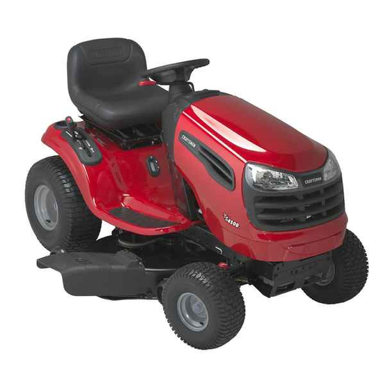
Owner's Manual
CRRFTSMRN °
LAWN TRACTOR
17.5 HP, 42" Mower
Electric Start
6 Speed Transaxle
Model No.
917.275370
i_
This product has a low emission engine which operates
differently from previously
built engines. Before you start the
engine, read and understand
this Owner's Manual.
IMPORTANT:
Read and follow all Safety
Rules and Instructions
before
operating this equipment.
For answers to your questions about
this product, Call:
1-800-659-5917
Sears Craftsman Help Line
5 am - 5 pm, Mon- Sat
Sears, Roebuck and Co., Hoffman Estates, IL 60179 U.S.A.
Visit our Craftsman
website:www.sears.com/craftsman
Advertisement
Table of Contents

Subscribe to Our Youtube Channel
Related Manuals for Craftsman 917.27537


Summary of Contents for Craftsman 917.27537
- Page 1 Sears, Roebuck and Co., Hoffman Estates, IL 60179 U.S.A. Visit our Craftsman website:www.sears.com/craftsman built engines. Before you start the this Owner's Manual. For answers to your questions about this product, Call: 1-800-659-5917 before Sears Craftsman Help Line 5 am - 5 pm, Mon- Sat...
- Page 2 Warranty... 2 SafetyRules ... 3 ProductSpecifications... 6 Assembly/Pre-Operation ... 8 Operation... 11 MaintenanceSchedule... 1 7 LIMITEDWARRANTYON CRAFTSMANRIDINGEQUIPMENT Fortwo (2) years from the date of purchase,if this CraftsmanRiding Equipmentis maintained,lubricatedand tuned up accordingto the instructionsin the owner'smanual, Searswill repair or replacefree of charge any parts that are foundto be defectivein materialor workmanshipaccordingto the guidelinesof coveragelisted below.Searswill also providefree labor for these applicablewarrantedparts for the two full years.
- Page 3 IMPORTANT: This cutting machine ing objects. Failure to observe injury or death. _I, WARNING: In order to prevent cidental starting when setting porting, adjusting or making always disconnect spark plug wire and place wire where it cannot contact plug. _WARNING: Do not coast neutral, you may lose control...
- Page 4 II. SLOPE OPERATION Slopes are a major factor related control and tip-over accidents, result in severe injury or death. tion on all slopes requires extra caution. you cannot back up the slope uneasy on it, do not mow it. • Mow up and down slopes, •...
-
Page 5: General Service
• Removegas-poweredequipmentfrom the truckor trailerand refuelit on the ground.If this is not possible,then refuel suchequipmentwith a portable container,ratherthan from a gasoline dispensernozzle. • Keepthe nozzle in contact with the rim of the fuel tank or containeropening at all times until fueling is complete.Do not use a nozzle lock-opendevice. - Page 6 RC12YC REPAIR PROTECTION AGREEMENTS Congratulations chase. Your new Craftsman® designed and manufactured dependable it may require repair from time to time. That's when having a Repair Protection can save you money and aggravation. Purchase a Repair...
- Page 7 Steering Wheel Insert (1) Hex Bolt 5/16-18 x 4 Steering Wheel Adapter Keys (2) Keys Steering Wheel (1) Large Flat Washer (1) 5/16 Lock Washer Steering Boot Seat (1) Washer 17/32 x1-3/16 x12 Gauge ) Knob (1) Oil Drain Tube For Future Use ©...
- Page 8 Your new tractor has been assembled unassembled for shipping purposes. all parts and hardware you assemble as necessary to insure proper TOOLS REQUIRED ASSEMBLY A socket wrench set will make assembly easier. Standard wrench sizes you need are listed below. (1) 3/4"...
- Page 9 7. Slide seat until a comfortableposition is reachedwhich allowsyou to press clutch/brakepedal all the way down. 8. Get off seat withoutmoving its ad- justed position. 9. Raise seat and tighten adjustment knob securely. Seat Seat Flat Washer djustment KnobN CHECK BATTERY Lift seat pan to raised position.
- Page 10 CHECK TIRE PRESSURE The tires on your tractor were overin- flated at the factory for shipping Correct tire pressure is important cutting performance. ° Reduce tire pressure to PSI shown "PRODUCT SPECIFICATIONS" of this manual. CHECK DECK LEVELNESS For best cutting results, mower ing should...
- Page 11 These symbols may appear on your tractor Learn and understand their meaning. REVERSE NEUTRAL HIGH ENGINE OFF REVERSE ENGINE ON OPERATION SYSTEM (ROS) FUEL OIL PRESSURE OVER TEMP LIGHT ATTACHMENT ATTACHMENT CLUTCH DISENGAGED CLUTCH ENGAGED LIGHTS ON FREE WHEEL (Automatic Models only) &...
- Page 12 KNOW YOUR TRACTOR READ THIS OWNER'S MANUAL TRACTOR Compare the illustrations with your tractor various controls and adjustments. Attachment Clutch Lever Light Switch " Th rottle/Choke Control Clutch/Brake Pedal Our tractors conform to the safety standards American National Standards Institute. ATTACHMENT CLUTCH LEVER...
- Page 13 The operation of any tractor the eyes, which glasses or eye shields adjustments or repairs. spectacles or standard TO USE YOUR TRACTOR TO SET PARKING BRAKE Your tractor is equipped with an operator presence sensing switch. When is running, any attempt by the operator to leave the seat without first setting...
-
Page 14: Reverse Operation
• The average lawn should be cut to ap- proximately 2-1/2 inches during season and to over 3 inches months. For healthier and better looking lawns, mow often and after moderate growth. • For best cutting performance, 6 inches in height should be mowed twice. - Page 15 TO TRANSPORT • Raise attachment lift to highest with attachment lift control. • When pushing or towing your tractor, be sure gearshift lever is in neutral position. • Do not push or tow tractor at more than five (5) MPH. NOTE: To protect hood from damage...
- Page 16 COLD WEATHER STARTING below) 6. When engine starts, leave throttle control in choke position until engine warms up and begins to run roughly. Once rough running begins, diately move the throttle control fast position. Engine warm-up take from several seconds minutes (the colder the temperature,...
-
Page 17: Maintenance
MAINTENANCE SCHEDULE FILL IN DATES AS YOU COMPLETE BE OLAR SERV,CE Check Operator Presence ROS Systems Check for Loose Fasteners Sharpen/Replace Mower Blades Lubrication Chart Check Battery Level Clean Battery and Terminals Check Transaxle Cooling Check V-Belts Check Engine Oil Level Change Engine Oil (with oil filter) -
Page 18: Brake Operation
TRACTOR Alwaysobserve safety ruleswhen per- forming any maintenance. BRAKE OPERATION If tractor requiresmore than five (5) feetto stop at highest speed in highest gear on a level,dry concreteor paved surface,then brakemust be checked and adjusted.(See "TOADJUST BRAKE"in the Serviceand Adjustmentssection of this manual). TIRES •... - Page 19 • To check blade balance, you will need a 5/8" diameter steel bolt, pin, or a cone balancer. (When using a cone balancer, follow the instructions supplied balancer.) NOTE: Do not use a nail for balancing blade. The lobes of the center appear to be centered, but are not.
- Page 20 Remove the drain tube and replace cap onto the end of the drain valve. Refill engine with oil through stick tube. Pour slowly. Do not overfill. For approximate capacity UCT SPECIFICATIONS" section manual. Use gauge on oil fill cap/dipstick checking level.
- Page 21 4. Immediatelywipe up any spilled gaso- line. Clamp_" CLEANING • Clean engine, battery, seat, finish, etc. of all foreign matter. & WARNING: TO AVOID SERVICE OR ADJUSTMENTS: Depress clutch/brake Place gearshift Place attachment Turn ignition key to "STOP" Make sure the blades Disconnect spark come in contact...
- Page 22 TO INSTALL MOWER 1. Raise attachmentlift leverto its highest position. 2. Slide mower undertractor with deflec- tor shield to right side of tractor. 3. Lower lift leverto its lowestposition. 4. Connectfront links to mowerdeck and securewith retainersprings. 5. Connectsuspensionarms to rear deck bracketsand secure with retainer springs.
- Page 23 TO REPLACE MOWER BLADE BELT The mower blade drive belt may be re- placed without tools. Park the tractor level surface. Engage parking BELT REMOVAL Remove mower from tractor REMOVE MOWER" in this section manual). Work belt off both mandrel idler pulleys.
- Page 24 Make sure belt is in all pulley grooves and inside all belt guides Install mower (See "TO INSTALL MOWER" in this section of manual). Engine Pulley-- Clutching Idler j Stationary Idler Transaxle TRANSAXLE GEAR SHIFT TRAL ADJUSTMENT The transaxle should be in neutral the gear shift lever is in neutral gate) position.
- Page 25 2. Connectone end of the BLACKcable to the NEGATIVE(-) terminal (C) of fully charged battery. 3. Connectthe other end of the BLACK cable (D) to good chassisground, awayfrom fuel tank and battery. TO REMOVECABLES, REVERSE ORDER- 1. BLACKcable first from chassis and then from the fully charged battery.
- Page 26 ENGINE Maintenance, repair, or replacement emission control devices and systems, are being done at the customers may be performed by any non-road repair establishment or individual. Warranty repairs must be performed by an authorized engine manufacturer's service outlet. TO ADJUST THROTTLE CONTROL CABLE...
- Page 27 Immediatelyprepareyour tractor for stor- ageat the end of the season or if the trac- tor will not be used for 30 days or more. _WARNING: Neverstore the tractor with gasoline in the tank insidea building where fumes may reachan open flame or spark.
-
Page 28: Troubleshooting
TROUBLESHOOTING CHART: See appropriate section in manual unless directed to Sears service center PROBLEM CAUSE Will not start 1. Out of fuel. Engine properly. Engine Bad spark plug. Dirty air filter. Dirty fuel filter. Water 8. Loose or damaged wiring. 9. - Page 29 TROUBLESHOOTING CHART: See appropriate section in manual unless directed to Sears service center PROBLEM CAUSE Loss of power Cutting fast. Throttle Build-up and trash under Dirty air filter. Low oil level/dirty Faulty spark Dirty fuel filter. Stale or dirty fuel. 9.
- Page 30 TROUBLESHOOTING CHART: See appropriate section in manual unless directed to Sears service center PROBLEM CAUSE Poorcut-uneven Bent blade mandrel. continued Clogged holes from buildup leaves, mandrels. Mower blades will 1. Obstruction not rotate mechanism. Worn/damaged belt. Frozen Frozen Poor grass 1.
- Page 31 TRACTOR - - MODEL NUMBER SCHEMATIC A_,_MFER (OPTIONAL) BLUE i -/---_ L -LI-GH-T-S-W-R - - - UGHT YOUR TRACTOR IS EQUIPPED WITH A SPECIAL ALTERNATOR THE LIGHTS ARE NOT CONNECTED BATTERY, BUT HAVE THEIR OWN ELECTRICAL BECAUSE OF THIS, THE IGNITION SWITCH BRIGHTNESS WILL CHANGE WITH ENGINE...
- Page 32 TRACTOR - - MODEL NUMBER ELECTRICAL 917.275370...
- Page 33 Nut, Keps Hex 1/4-20 unc 4207J Cable Ground 6 Ga. 12" black 192749 Switch Seat 193350 Switch Ign 140403 Key Ign Molded Craftsman 110712X Switch Light/Reset 193374 Harness Ign 71110408 Bolt BIk. Fin Hex 1/4-20 uric x 1/2 131563 Cover Terminal Red...
- Page 34 TRACTOR - - MODEL NUMBER 917.275370 CHASSIS AND ENCLOSURES -209 _209 38_4 chassis-Laser-It.stlt...
-
Page 35: Chassis And Enclosures
TRACTOR - - MODEL NUMBER CHASSIS AND ENCLOSURES NOTE: 917.275370 PART DESCRIPTION 174619 Chassis Stamping 176554 Drawbar 155272 Bumper Hood/Dash 193510X012 Dash STD533710 Bolt, Carriage 3/8-16 x 1 174996 Panel, Dash, L.H. 172105X010 Panel, Dash, R.H. 17490608 Screw Thdrol 3/8-16 x 1/2 185682X613 Hood Assembly Laser 184921... - Page 36 GROUND DRIVE TRACTOR . . MODEL NUMBER 917.275370 • 48 drive-fender.stlL41...
-
Page 37: Ground Drive
TRACTOR - - MODEL NUMBER GROUND DRIVE PART DESCRIPTION Transaxle Peerless 206-545C (See Breakdown) 146682 Spring Brake Return 123666X Pulley Transaxle 12000028 Ring Retainer 121520X Strap Torque 30 Degrees 17060512 Screw 5/16-18 x 3/4 192502 Rod Shift Fender Adjust STD561210 Pin Cotter 1/8 x 1 CAD 105701X Washer Plate Shift... -
Page 38: Steering Assembly
TRACTOR - - MODEL NUMBER 917.275370 STEERING ASSEMBLY -_97 ,_42 J" 1" steering pl.lt 58... - Page 39 TRACTOR STEERING ASSEMBLY NOTE: All component dimensions given in U.S. inches - - MODEL NUMBER 917.275370 PART DESCRIPTION 186780 Steering Wheel 175131 Axle Assembly STMP Dropped STL 169840 Spindle Assembly, L.FI. 169839 Spindle Assembly, R.FI. 6266H Bearing, Race, Thrust, Hardened 121748X Washer 25/32 x 1-5/8 x 16 Ga.
-
Page 40: Optional Equipment
TRACTOR - - MODEL NUMBER ENGINE OPTIONAL EQUIPMENT Spark Arrester KEY PART NO. NO. DESCRIPTION 170545 Control, Throttle/Choke 17720408 Screw, Hex Head, Thread Cutting 1/4-20 x 5/8 Engine, Briggs Model No. 31C707-0230-E1 (See Breakdown) 137352 Muffler 165291 Gasket 148456 Tube Drain Oil Easy 169837 Shield Brn/Dbr Guard 137180... -
Page 41: Seat Assembly
TRACTOR - - MODEL NUMBER SEAT ASSEMBLY seat It.knob 9 PART DESCRIPTION 188716 Seat 180166 Bracket, Pivot, Seat 71110616 Bolt 19131610 Washer 13/32 x 1 x 10 Ga. 145006 Clip, Push-In Hinged STD541437 124181X Spring, Seat 17000616 Screw 3/8-16 x 1-1/2 19131614 Washer 13/32 x 1 x 14 Ga. -
Page 42: Wheels And Tires
TRACTOR - - MODEL NUMBER DECALS PART DESCRIPTION 193308 Decal Fender Opr. Inst. 186377 Decal HP Engine 186280 Decal Hood RH 179128 Decal Deck 186281 Decal Hood LH 133644 Decal Customer Maintenance 195879 Decal Replacement 138047 Decal Battery 186282 Decal Fender 149516 Decal... -
Page 43: Lift Assembly
TRACTOR - - MODEL NUMBER LIFT ASSEMBLY PART DESCRIPTION 159460 Lift Lever Inner Wire Assembly 159471 Shaft Assembly, Lift 105767X Pin, Groove 12000002 E-Ring 19211621 Washer 21/32 x 1 x 21 Ga. 120183X Bearing, Nylon 125631X Grip, Handle, Fluted 122365X Button, Plunger, Red 139865 Link, Lift, L.H. -
Page 44: Mower Deck
TRACTOR - - MODEL NUMBER 917.275370 MOWER DECK ii47142 D man-topath stir 3... - Page 45 TRACTOR - - MODEL NUMBER MOWER DECK PART DESCRIPTION 165892 Mower Deck Assembly, 42" STD533107 Bolt 138017 Bracket Assembly, Sway Bar, Front 165460 Bracket Sway Bar 38/42" eck STD624008 Retainer Spring 178024 Bar Sway Deck 850857 Bolt, Hex 3/8-24 x 1.25 Gr. 8 STD551137 Washer, Lock 140296...
- Page 46 TRACTOR PEERLESS TRANSAXLE - - MODEL NUMBER 206-545C O _71B MODEL and SERIAL NUMBERS HERE i-o_',,;,_o% - - MODEL NUMBER 917.275370 ;426 'o' ]...
- Page 47 TRACTOR PEERLESS TRANSAXLE - - MODEL NUMBER 206-5450 PART DESCRIPTION 772147 Transaxle Cover 780086A Needle Bearing 5/8" 770128 Transaxle Case 776395 Countershaft 776409 Output Shaft 778364 Spur Gear (38 teeth) 778369 Spur Gear (15 teeth) 778330 Spur Gear (11 teeth) 792180 Shift Key 792047...
- Page 48 TRACTOR BRIGGS ENGINE-MODEL NUMBER 31C707, TYPE NUMBER 0230-E1 358 ENGINE GASKET SET 20@ 6170 691 (_ 8420 524 @ 1019 LABEL KIT I 1088OWNER'S MANUAL I [ 1036 EMISSION LABEL ] - - MODEL NUMBER 917.275370 43,_ 307_ 868_) 943 O 1022 1266 0 584_...
- Page 49 TRACTOR BRIGGS ENGINE-MODEL NUMBER 31C707,TYPE 1 o22 1022 102_: 616_ 404,, _ 614_ / !J - - MODEL NUMBER 917.275370 NUMBER 0230-E1 6170 635.m4_ 267 _' 1095 VALVE GASKET 617 0 1022 ..4_ 524 O...
- Page 50 TRACTOR BRIGGS ENGINE-MODEL NUMBER 310707,TYPE 142_ _}-- 106 1869 276@ 95o_ 4311 1266A 0 1266 - - MODEL NUMBER 917.275370 NUMBER 0230-E1 108A _ 1091 127 G 121 CARBURETOR OVERHAUL 104 _ 127_ 105 _ 106 [_ 117_ 977 CARBURETOR GASKET SET 137 0 276@ 987(_...
- Page 51 TRACTOR BRIGGS ENGINE-MODEL NUMBER 310707,TYPE 305A _ 3041 801 (_ 697 _ 603 _ 310 1 802 (_ 87-q-- _o1_ (_ 783A_ 544A 310 [ 803A 513_ _/311A NOTE: For Replacement Starter Motor, See Reference 309. - - MODEL NUMBER 917.275370 NUMBER 0230-E1 1265...
- Page 52 TRACTOR BRIGGS ENGINE-MODEL NUMBER 310707,TYPE PART DESCRIPTION 697174 Cylinder Assembly 399265 Kit-Bushing/Seal 391086 Seal-Oil (Magneto Side) 697106 Sump-Engine 698147 Head-Cylinder 692410 Gasket-Cylinder Gasket-Breather 697109 697157 Screw (Breather Assembly) Tube-Breather 697113 697110 Gasket-Crankcase 690360 Screw (Cylinder Head) 690946 Plug-Oil Drain Crankshaft 697127 690947 Seal-Oil (PTO Side)
- Page 53 TRACTOR BRIGGS ENGINE-MODEL NUMBER 310707,TYPE PART DESCRIPTION 89838 Wrench-Spark Plug 691691 Washer (Governor Crank) 697122 Elbow-Intake 698083 Filter-Air Cleaner Cartridge 691261 Washer (Starter Cable) 696459 Alternator 691532 Strap-Starter 691251 Nut (Governor Control Lever) 693699 Drive-Starter 510A 497606 Drive-Starter 692024 Clutch-Drive 697086 Dipstick 691032...
- Page 55 SUGGESTED GUIDE FOR SIGHTING SLOPES FOR SAFE OPERATION ..,,... ONLY RIDE UP AND DOWN HILL, NOT ACROSS HILL 15 DEGREES MAX. down the face of slopes, never across the face. Do not mow ARNING: To avoid serious injury, operate your tractor up and slopes greater than 15 degrees.
-
Page 56: Installation
iiiiiiiiiiiiiiiiiiijiii,_ iiiiiiiiiiiiiiiii For repair - in your HHHHHHHHh,_ iiiiiiiiiiiiiiiii iiiiiiiiiiiiiiiiiii lawn and garden iiiiiiiiiiiiiiiiiii iiiiiiiiiiiiiiiiiii no matter iiiiiiiiiiiiiiiiiii iiiiiiiiiiiiiiiiiii For the replacement iiiiiiiiiiiiiiiiiii iiiiiiiiiiiiiiiiiii iiiiiiiiiiiiiiiiiii owner's manuals iiiiiiiiiiiiiiiiiii iiiiiiiiiiiiiiiiiii For Sears professional iiiiiiiiiiiiiiiiiii iiiiiiiiiiiiiiiiiii and items like garage iiiiiiiiiiiiiiiiiii iiiiiiiiiiiiiiiiiii iiiiiiiiiiiiiiiiiii iiiiiiiiiiiiiiiiiii iiiiiiiiiiiiiiiiiii...
Need help?
Do you have a question about the 917.27537 and is the answer not in the manual?
Questions and answers