
Related Manuals for GFA 10003166 10011


Summary of Contents for GFA 10003166 10011
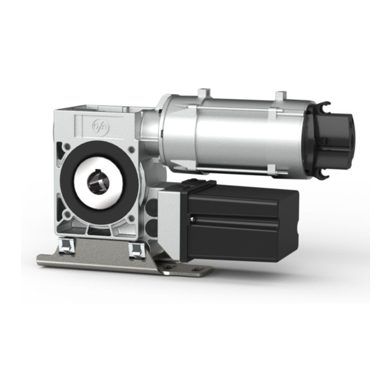
- Page 1 Installation Instructions ELEKTROMAT SI 25.15-30,00 Model: 10003166 10011 -en- Status: 30.05.2018...
- Page 2 GfA ELEKTROMATEN GmbH & Co. KG Wiesenstraße 81 D-40549 Düsseldorf www.gfa-elektromaten.de info@gfa-elektromaten.de...
-
Page 3: Table Of Contents
Table of contents General safety information ....................4 Technical Data ........................ 5 Mechanical installation ....................6 Electrical installation ..................... 10 Limit switch adjustment ....................11 Motor connection ......................12 ... -
Page 4: General Safety Information
1 General safety information Specified normal use The drive unit is intended for doors, which have to be secured against falling down; a safety brake is included in the gearbox. The drive unit is directly mounted on the door shaft. The safe operation is only guaranteed with normal specified use. -
Page 5: Technical Data
2 Technical Data Type SG 63F Output torque Output speed Output shaft / hollow shaft 30,00 Locking torque moment Safety brake (testhouse/approval number) 14-003612-PR02 Maximum output speed open / close 26 / 15 for frequency inverter operation Supply voltage 3N~ 400 Operating current 2,30 Operating frequency... -
Page 6: Mechanical Installation
3 Mechanical installation Prerequisites The permissible loads on walls, fastenings, mountings and transmission elements must not be exceeded, even for maximum holding torques or locking torques (▶ refer to technical data). Connection elements ▶ Self-locking connection ▶ Utilize the hole diameter ▶... - Page 7 Mounting Three elongated holes are provided for mounting. ▶ Use at least 2 of these (①) for mounting. Always use elongated hole ❶. A key is used to connect to the door shaft. ▶ Use a key that is at least as long as the hollow shaft (②). BAGAD0 2 0 0 1 _Z0 0 2...
- Page 8 Installation The descriptions below apply to general door specifications. The specifications of the door manufacturer must also be observed during installation. Warning - Potential injury or danger to life! During installation, be sure to use a lifting device that has a sufficient load-carrying capacity.
- Page 9 BAGAE0 2 0 0 7 _Z0 0 2 ▶ Attach the drive unit. ▶ Tighten all connection elements (M12) to BAGAE0 2 0 1 1 _Z0 0 3 75 Nm. Install all other connection elements according to the specifications of the door manufacturer.
-
Page 10: Electrical Installation
4 Electrical installation Warning - Danger to life from electric current! Switch the mains OFF and check that the cables are de-energised Observe the applicable regulations and standards Make a proper electrical connection Use suitable tools Performing electrical installation Remove the cover. -
Page 11: Limit Switch Adjustment
5 Limit switch adjustment The adjustment of the final limit positions OPEN and CLOSE is described in the instructions for the door control panel. -
Page 12: Motor Connection
6 Motor connection Motor X13 Motor plug 7 Alternative motor connection Motor X13 Motor plug... -
Page 13: Limit Switch Connection
8 Limit switch connection Thermal contact S10 Manual operation X12 DES connection Safety circuit Channel B (RS485) Ground Channel A (RS485) Safety circuit Supply network... -
Page 14: Emergency Manual Operation (Emergency Hand Crank)
9 Emergency manual operation (emergency hand crank) The emergency manual operation is designed for opening or closing the door without power supply. Its activation interrupts the control voltage. Electrical operation is no longer possible. Warning – Injuries due to incorrect operation or falling objects! ... - Page 15 Plug in the crank and turn until it engages (①). Open or close by turning the crank (②). After use, the crank may be attached to the drive unit. ▶ Attach as illustrated.
-
Page 16: Completion Of Commissioning / Testing
10 Completion of commissioning / testing Check the following components and after that, mount all covers. Gearbox Check drive unit for oil loss (a few drops are not critical). Protect output shaft permanently against corrosion. Safety brake in the gearbox The safety brake requires no maintenance or inspection. - Page 17 Emergency manual operation Function to be checked in a de-energised state. Carry out functional test only between final limit positions. Limit switches Check the final limit positions by opening and closing the door completely. The safety zone must not be reached. Entire drive unit Note! ...
-
Page 18: Declaration Of Incorporation / Conformance
Declaration of conformity in terms of EMC Directive 2014/30/EU We, the GfA ELEKTROMATEN GmbH & Co. KG hereby declare that the following products are conform with the above EC Guideline and are only intended for installation in door equipment. SI 25.15-30,00...
Need help?
Do you have a question about the 10003166 10011 and is the answer not in the manual?
Questions and answers