
Related Manuals for Bince RTS202 Series

Summary of Contents for Bince RTS202 Series
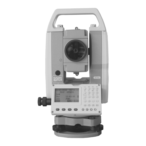
- Page 1 宾测 RTS200/RTS200R Series Total Station Instruction Manual RTS202 RTS202R Xiamen City Bince Trading Co., Ltd.
- Page 2 Dear Customer: Congratulations! We, BinCe are proud to present you with these series instrument. Your total station is a rugged and reliable instrument whose performance and design are not surpassed. To fully appreciate and protect your investment, we suggest that you take the necessary time to read and fully understand this manual.
-
Page 3: Table Of Contents
Contents 1. Precautions for Safety................... 1 1.1 Note........................1 1.2 Definition of Indication.................. 2 1.3 Safety Standards for Laser (RTS200R series)..........4 2. Preparation before Measurement............... 6 2.1 About Battery....................6 2.1.2 Replace the Battery..................7 2.1.3 Recharge the Battery...................7 2.2 Setting Up the Instrument................8 2.3 Centering and Levelling-Up................ - Page 4 7. Stake out Measurement................39 7.1 Distance Stake out..................39 7.2 Coordinates Stake out Measurement............41 7.3 REM Stake out Measurement..............43 8. Area.........................44 8.1 Area Calculation by Measured Data............44 8.2 Area Calculation by Reading Existed Coordinates.........45 9. Offset Measurement..................47 9.1 Single-distance Offset Measurement............47 9.2 Angle Offset Measurement................
- Page 5 20.2 Input Road Horizontal Elements............. 79 20.2.1 Input Line Element..................79 20.2.2 Input Circle Element................80 20.2.3 Input Spiral Element................81 20.2.4 Road Horizontal Element Editing............81 20.3 Input Road Vertical Elements..............83 20.3.1 Input Vertical Road Element..............83 20.3.2 Edit Vertical Road Element..............84 20.4 Road Calculation..................86 20.4.1 Input the road width element..............
- Page 6 23.4 View known points data................112 23.5 Clear all known points’ data..............113 24. Code Management................... 114 24.1 Edit Code list....................114 24.2 Clear all Codes...................115 25. Warning and Error Messages..............116 26. Check and Adjustment................117 26.1 The Instrument Constant.................117 26.2 Tubular Level.....................118 26.3 Circular Level....................
-
Page 7: Precautions For Safety
1. Precautions for Safety 1.1 Note ◆ Don’t collimate the sun directly Avoid to insolate the instrument, and don’t collimate the sun directly for protecting eyes and instrument. ◆ Avoiding the librations on the instrument When transporting, keep the instrument in the case and try your best to lighten librations. ◆... -
Page 8: Definition Of Indication
● Do not put the battery in the fire or high temperature condition. Explosion, damage could result. ● Do not use the battery which is not specified by BinCe. Fire, electric shock or burn could result. ● Do not use the power cable which is not specified by BinCe. Fire could result. - Page 9 ! CAUTION ● Do not touch the instrument with wet hand. Electric shock could result. ● Do not stand or seat on the carrying case, and do not turn over the carrying case arbitrarily, the instrument could be damaged. ● Be careful of the tripod tiptoe when setup or move it. ●...
-
Page 10: Safety Standards For Laser (Rts200R Series)
1.3 Safety Standards for Laser (RTS200R series) RTS200R series adopt the class of Laser Product according to IEC Standard Publication 60825-1 Amd. 2:2001. According this standard, EDM device is classified as Class 3R Laser Product when reflectless measurement is selected, when the prism and reflective sheet is selected as target, the output is equivalent to the safer class 1. - Page 11 1.4 About User 1) This product is for professional use only! The user is required to be a qualified surveyor or have a good knowledge of surveying, in order to understand the user manual and safety instructions, before operating, inspecting or adjusting. 2) Wear required protectors (safety shoes, helmet, etc.) when operating.
-
Page 12: Preparation Before Measurement
2. Preparation before Measurement 2.1 About Battery 2.1.1 Battery Power Symbol Meas ⊥ DIST SHV1 SHV2 0 S E T Measurement is possible The battery is lower, it is better to replace or recharge it Measurement is impossible, it is necessary to replace or recharge battery NOTE: ◆... -
Page 13: Replace The Battery
2.1.2 Replace the Battery 1) Remove the battery ① Press the button downward as shown left ② Remove the battery by pulling it toward you 2) Mount the battery ① Insert the battery to the instrument ② Press the top of the battery until you hear a Click. -
Page 14: Setting Up The Instrument
2.2 Setting Up the Instrument Mount the battery in the instrument before performing this operation because the instrument will tilt slightly if the battery is mounted after leveling. I. Set up the tripod first: extend the extension legs to suitable lengths and tighten the screws on the midsections. - Page 15 Screw B Screw A Turn the instrument approximately 90°. Adjust screw C, till the bubble in the center of the level. Screw C Repeat above steps until the bubble remains in the center of the plate level while the instrument is rotated to any position. 5.
-
Page 16: Accurate Levelling-Up With Electronic Level On Screen
2.4 Accurate Levelling-Up with Electronic Level on screen It is convenient for RTS200/RTS200R series to level-up with electronic level, especially when it is difficult to observe the circular level and plate level. Tilt Value 1. Power on the instrument and press key { Tilt Mode directly, and the electric level displays on screen. -
Page 17: Basic Functions
3. Basic Functions 3.1 Nomenclature Handle Handle screw Optical sight Objective Vertical motion clamp Vertical tangent knob Plate level Keypad Model label Circular level RS-232C port Tribrach... -
Page 18: Basic Key Operation
3.2 Basic Key Operation Keys Description F1~F4 Select the functions matching the softkeys 1.Input number when numeric input 2.Input characters when alphabetic input Input a decimal point ● ± Input plus/minus sign Power Power on/off Enter into setting mode directly ★... -
Page 19: Display
3.3 Display The LCD could display 6 lines with 20 characters per line.In measurement mode, it displays some common information in above 5 lines and displays soft functions in the last line. Status screen Instrument model 02/12/2010 10:52:35 RTS202 Application software version JK0002 13-03-08 Current power... -
Page 20: Mode Diagram
3.4 Mode Diagram Meas mode Meas 02/12/2010 10:52:35 [MEAS] 0⊥ RTS202 JK0002 13-03-08 JOB1 MEAS MEM CNFG {ESC} DIST SHV1 SHV2 0 S E T CORD MENU HOLD H S E T {ESC} [MEM] EDM O C C OFST R E C Memory 1.JOB 2.Known data... - Page 21 Code 1.Code Edit Menu 2.Clear List 1.Inverse 2.Polarize 3.Repeat Measure 4.Arc staking out 5.Road Calculation Cnfg mode 02/12/2010 10: 52:35 RTS202 JK0002 13-03-08 JOB1 MEAS MEM CNFG {ESC} [CNFG] Config 1.Meas condition 2.Inst.config 3.Inst.adjust 4.Com setting 5.Unit [Func] Config 1.Date&Time 2.Key Function...
-
Page 22: Power On/Off
Setting mode (Press {★} directly) Inst. Config 1.Backlight : YES 2.Laser 3.contrast 4.Ret. Lev. Inst. Config 1.Key Beep : YES 2.Signal 3.5 Power On/Off I. Power on 1.Confirm the instrument is leveling, press the red key },then press the key {skip}. POWER Demo mode 10 points limited... -
Page 23: Registration & Demo Mode
When you start RTS200/RTS200R series for the first time you will see the registration screen. To activate RTS200/RTS200R program you need to call BinCe local dealer, or email us the instrument serial number. We will then issue you a registration number that you can enter in the No. -
Page 24: How To Input Number And Alphabet
3.6 How to Input Number and Alphabet 1. Enter into input code status (See§21.1 Input a code), the cursor is blinking and ready to input. The 001:CODEAB 002: note “A” at the top right corner shows the active 003: input mode, you can press the key { } to switch 004: shift... -
Page 25: How To Configure
3.7 How to Configure Press key {★} on panel directly to enter into in any Inst. Config status, and do some basic settings. 1.Backlight 2.Laser 3.contrast 1. Backlight 4.Ret. Lev. Press numeric key { }, then press left key { } or right key { } to turn on or not. - Page 26 Press Func key to turn to page 2 of Star Configure menu 1. Key beep Inst. Config 1.key Beep : YES Press numeric key {5}, then press left key { } or right 2.signal key { } to turn on key beep or not, if you select NO, you will not hear the beep voice when press any key.
-
Page 27: How To Set Parameters
3.8 How to Set Parameters Press key { } on the keyboard to enter into config mode in any status, all the following items can be set. 3.8.1 Measure Condition Setting 1. Press key { } to enter into config mode. Config 1.Meas condition 2.Inst. - Page 28 Table 3-1 List of measurement condition setting Options Item 1.Dist Mode SD﹡/HD/VD 2.Tilt Mode XonYon﹡/XonYoff/XoffYoff 3.C&R crn .14﹡/.20/No 4.V. obs Zenith﹡/VA/V90 5.H. obs HAR﹡/HAL 1.HA Buzzer No﹡/Yes 2.Coord N-E-Z﹡/E-N-Z 1〞﹡/5〞/10〞; 3.Ang .reso 0.0002g﹡/0.001g/0.002g; 0.005mil﹡/0.02mil/0.05mil 4.Code eff The manual input code is available once or always 5.Vd mode Display mode of vertical distance: to instrument center or to the ground...
-
Page 29: Instrument Basic Setting
3.8.2 Instrument Basic Setting 1. Press key { } to enter into config mode. Config 1.Meas condition 2.Inst. config 2. Select “ to set instrument basic 2.Inst. config” 3.Inst. adjust parameters. Three items display. 4.Com setting 5.Unit Inst config :15min 1.Power off 3. -
Page 30: Communication Port Setting
3.8.3 Communication Port Setting Please set communication parameters before connecting your computer. 1. Press key { } to enter into config mode. Config 1.Meas condition 2.Inst. config 2. Select “ to set the parameters of 3.Inst. adjust 4.Com setting” 4.Com setting communication port. -
Page 31: Unit Setting
3.8.4 Unit Setting 1. Press key { } to enter into config mode. Config 1.Meas condition 2.Inst. config 2. Select “ to set unit. 5.Unit” 3.Inst. adjust 4.Com setting 5.Unit 3. Change the settings if necessary. Press keys { Unit } to select items and press keys { } / { } to set... -
Page 32: Date & Time Setting
3.8.5 Date & Time Setting The date and time displays at the status mode. 1. Press key { } to enter into config mode. Config 1.Date&Time 2.Key Function 2. Select “ 1.Date & Time” Date and Time Input date time. date format: month/date/year. - Page 33 Following items can be defined: Items Descriptions DIST Start distance measure SHV1 Display switching between SD/HAVA, HD/HA/VA and VD/HA/VA SHV2 Display switching between SD/HD/VD and SD/HA/VA 0SET Set horizontal angle to 0 CORD Enter coordinate measurement menu MENU Enter program menu HOLD Hold the horizontal angle HSET...
-
Page 34: Edm Setting
Key Save KEY FUNCTION SAVE Press key {1} to save the current key setting in 1.User Define 1 2.User Define 2 User Define 1 Press key {2} to save the current key setting in User Define 2 Key Resume KEY FUNCTION RESUME 1. - Page 35 Table 3-5 EDM setting Options Item 1.Mode Fine “r”﹡/ FineAVG 3 / Fine “s” / Rapid “s” / Tracking 2.Ref lector Prism﹡/ Sheet/ No prism 3.Pri. const -99~99 4.Temp. -30~60℃(20℃﹡)/-22~140℉ 5.Pressure 500~1400hPa(1013hPa﹡); 375~1050mmHg(760mmHg﹡); 14.8~41.3 inchHg (29.9inchHg﹡) 500~1400mbar(1013mbar﹡); 7.2~20.3Psi(14.7Psi﹡) 6.ppm -499~499(0﹡), Press F1: [ ] to set temperature, pressure and ppm as 0PPM...
-
Page 36: Angle Measurement
4. Angle Measurement 4.1 Measure a Horizontal Angle of Two Points 1. Sight the 1 target. Meas Press F4: [ ] twice to set the 1 target as 0SET 0°at P1 in the measure mode. 85°55′50″ Press [ ] or [ ] to change display status SHV1 SHV2... -
Page 37: Set The Horizontal Angle To A Required Value
4.2 Set the Horizontal Angle to a Required Value 1. Take your instrument sight the 1 target. Meas Press F4: [ ] at P2 in the measure mode. HSET VA 302.5432gon HA 0.0000gon 2. Select the first item 1.Azimuth, and input the CORD MENU HOLD H S E T required value in Azimuth filed, then press { } to... -
Page 38: Distance Measurement
5. Distance Measurement Please set the following items before distance measurement: Measurement condition ( See §3.8.1 Measure Condition Setting) ● EDM (See §3.8.6 EDM setting ) ● 【Procedure of distance measurement】 Meas 1. Aim at the target, press F3:[ , the display mode SHV2] of basic measurement will change to SD/HD/VD mode, and then press F1:[... - Page 39 NOTE: ◆ Make sure that the target setting in the instrument matches the type of target used. ◆ If the objective lens is dirty, it will affect the accurate of measured results. Dust it off with your special brush and wipe it with your special cloth (in your carrying case) before putting away.
-
Page 40: Coordinate Measurement
6. Coordinate Measurement It is possible to find the 3D coordinates of a target by coordinate measurement. Please input the occupied coordinate, instrument height, target height, backsight coordinate (or azimuth angle) and azimuth before coordinate measurement. ○ Target Ht Inst. Ht Target point Occiped point 6.1 Input the Occupied Point Data... - Page 41 5. Press F3: [ ] to record the data in active PT# occupied data list, see “§18.1 Record Occupied Data”. Inst.H 1.500m You could press F1: [ ] to read the existed data READ 0.000 0.000 for occupied point from memory. You could also press 0.000 to enter Resection program to get the station READ R E S R E C...
-
Page 42: Azimuth Setting
NOTE: ◆ The point number that was read is displayed until the current JOB is changed or a new point number is selected. ◆ If more than two points with the same point name exist in the current JOB, the instrument finds the first recorded data only. -
Page 43: Coordinate Measurement
Note: ◆ You can select “ ” to input the azimuth angle directly. 1. Azimuth ◆ After input the coordinate of backsight, you can press F1:[ to check for MEAS backsight checking, between station Azimuth 45°00′00″ backsight, dHD and dVD between calculated Tgt.H 1.000m backsight and measured backsight will be display. - Page 44 【Procedure of 3D coordinates measurement】 1. Aim at the target point. Coordinate 2. Select “ ” to start. The coordinate value of 2. Measure 1. Occ. Orientation 2. Measure the target is displayed. 3. EDM 3. Press F2: [ ] to re-input the occupied data if TAGT 4.
-
Page 45: Stake Out Measurement
7. Stake out Measurement Stake out measurement is used to stake out the required point. The difference between the previously inputted data to the instrument (the stake out data) and the measured value can be displayed by measuring the horizontal angle, distance or coordinates of the sighted point. - Page 46 【Procedure of distance stake out measurement】 Menu 1. Press F2: [ ] at P2 in the measure mode. MENU 1.Coordinate 2.Stake out Select “ ”. 2. Stake out 3.Area 4.Offset 5.MLM 1. Occ. Orientation 2. Select “ ”. 1. Occ. Orientation 2.
-
Page 47: Coordinates Stake Out Measurement
6. Horizontally rotate the instrument until “dHA” is S-O dSD↓ 0.000m dHA← 0.0000gon near 0 and set the target on the sight line. 149.3610gon 334.9916gon Press F1: [ ] to start distance measurement. MEAS MEAS NEXT MOKS 7. The difference of measured and stake out value ”... - Page 48 Stake out 1.Height 2.Angle & Dist 3. Press Esc, then Select “ ”, then select 2. S-O data 3.Coord “ ”. 3.Coord 4. Input the coordinates of the stake out point. Press F1: [ ] to read the existed coordinates as READ Tgt.H 1.500m...
-
Page 49: Rem Stake Out Measurement
7.3 REM Stake out Measurement Perform this operation to find a point where a target cannot be directly installed, see “§11 REM”. 【Procedure of REM stake out measurement】 1. Set a target directly below or directly above the point 1. Occ. Orientation 2. -
Page 50: Area
8. Area Calculate an area shaped with several points. The coordinate data of the points could be either measured or input by hand. Input: Output: Coordinates: P1 (N1, E1) Area:S P2 (N2, E2) P3 (N3, E3) … NOTE: ◆ The number of points: 3 ~ 30. ◆... -
Page 51: Area Calculation By Reading Existed Coordinates
3. Press F4: [ ] to re-measure distance or press MEAS 10.000 I F1: [ ], the measured data is set as“Pt-01”. 5.000 53.493 152.6296gon 62.1314gon 0OK0 MEAS 01:Pt_01 4. Repeat steps 2 and 3 till all points are measured one 02:Pt_02 03:Pt_03 by one. - Page 52 3. Pt#: Known point data saved in the active JOB or in Occ. the coordinate search JOB. Coord Occ./Coord: Coordinate data saved in the active JOB or in the coordinate search JOB. ↑↓.P T O P LAST SRCH 01:O1 4. Select the first point in the list and press key { 02:Pt1 to set.
-
Page 53: Offset Measurement
9. Offset Measurement Offset measurement are performed in order to find a point where a target cannot be installed directly or to find the distance and angle to a point which cannot be sighted. It is possible to find the distance and angle to a point you wish to measure (target point) by installing the target at a location (offset point) a little distance from the target point and measuring the distance and angle from the surveying point to the offset point. - Page 54 3. Select [ , or press F3: ] at MENU 4. Offset [OFST Offset P3 of basic measurement menu. 1.Occ. Orientation 2.Offset/Dist 4. Select “ ” to input the instrument 1. Occ. orientation 3.Offset/Angle occupied data, see “§6.1 Input the occupied point 4.Offset/2Dist data”.
-
Page 55: Angle Offset Measurement
9.2 Angle Offset Measurement Sighting the direction of the target point to find it from the included angle. Set offset points for the target point on the right or left sides of and as close as possible to the target point and measure the distance to the offset points and the horizontal angle of the target point. -
Page 56: Dual-Distance Offset Measurement
9.3 Dual-Distance Offset Measurement By measuring the distance between the target point and the two offset points. Set two offset points (1st target and 2nd target) on a straight line from the target point, measure the 1st and 2nd target, then input the distance between the 2nd target and the target point to find the target point. - Page 57 5. Sight the 2 target, press F1: [ ] and MEAS Observe 2nd offset measured data will display, press F4: [ ] to accept 10.186 this value. 10.000 10.000 MEAS MOKS 6. Input the distance from 2 point to the target point and press key { }, the angle and distance of Dist...
-
Page 58: Mlm
10. MLM MLM is used to directly measure slope distance, horizontal distance and the height difference from one base point to other points without moving the instrument. NOTE: ◆ The last measured data could be set as the base point for the next starting operation. ◆... -
Page 59: Change The Starting Point
4. Aim at the next point P3 and press F1: [ ] to begin measure. Repeat this operation to measure other target points. 5. Press F2: [ ], the last target measured MOVE M L M MOVE MEAS becomes the new starting position to perform MLM of next target. -
Page 60: Rem
11. REM REM is a function used to measure the coordinate and height to a point where a target cannot be directly installed such as power lines, overhead cables or bridges, etc. Target point B α α B’ Here is the equation used to calculate the data presented in above figure: Ht=H1+Scosα1tgα2-Ssinα1 【Procedure of REM】... -
Page 61: Resection
12. Resection Resection program is used to determine the coordinates of an instrument station (unknown) by measuring several known points. Coordinate data in memory could be read. Input Coordinates of known points: Xi, Yi, Zi Measured HA: Hi Measured VA: Vi Measured distance: Di Output Coordinate of occupied data: Xo, Yo, Zo... -
Page 62: Coordinate Resection
12.1 Coordinate Resection Between 2 and 5 known points can be measured by distance measurement and angle measurement. 【Procedure of coordinate resection】 1. Select [ ] at P2 of basic measurement mode, MENU Menu then press Func key to turn to page 2, and then select 1.REM 2. -
Page 63: Elevation Resection
6. Repeat procedures 4 and 5 of other points. Resection No.2Pt When the minimum quantity of measured data 10.188m 189.9284gon required for the calculation is present, [ ] will be CALC 47.2432gon displayed. Tgt.H 000000m Press F1: [ ] to calculate. Instrument CALC CALC TNOT... - Page 64 3. After setting the elevation for the first known point, No. 1Pt# press F3: [ ] to set the second point data. NEXT 4. After all known points data have been set, press F4: Tgt.H MEAS READ R E C NEXT MEAS Press F1: [ ] to read existed coordinate data.
-
Page 65: Resection Calculation Process
12.3 Resection Calculation Process The N, E coordinates are found by angle and distance measurement equations, and the instrument occupied coordinates are found using the least squares method. The Z coordinate is found by treating the average value as the instrument occupied coordinate. Calculation begins Hypothetical coordinates are found The measured equation for the angle is prepared... -
Page 66: Precautions When Performing Resection
12.4 Precautions When Performing Resection In some cases it is impossible to calculate the coordinates of occupied point if the unknown point and three or more known points are arranged on the edge of a single circle. It is also impossible to calculate if the included angle between the known points is too small. -
Page 67: Point Projection
13. Point Projection Point projection is used for projecting a point to an established baseline. The point to project can be either measured or input. Displays the distances from the first point and point to project to the position at which a line extending from point to project intersects the baseline at right angles. - Page 68 3. Input the instrument occupied data, see “§6.1 Input Point projection 1.Occ. Orientation the occupied point data”. 2.Define baseline 3.Point projection 4. Select “ ”. 2. Define baseline Point projection 1.Occ. Orientation 2.Define baseline 3.Point projection 5. Input the first point data, or press F1: [ ] to use Define 1st Pt.
-
Page 69: Point Projection
13.2 Point Projection The baseline must be defined before performing point projection. 【Procedure of point projection】 1. Select “ ” after finishing defining 3. Point projection baseline. Point projection 1.Occ. Orientation 2. Input the point coordinate. 2.Define baseline Press F2: [ ] to measure the point to project. -
Page 70: Stake Out Line
14. Stake out Line Stake out line is used for stake out a required point at a designed distance from the base line and for finding the distance from the baseline to a measured point. Grade Fill Offset Baseline Azimuth Length 14. -
Page 71: Stake Out Line-Point
14. 2 Stake Out Line-Point This measurement can be used to find the required point coordinates by inputting the length and offset based on baseline. Y direction X direction Baseline Offset Length Required point Length: Distance along the baseline from 1 point to the position at which a line extending from the required point intersects the baseline at right angles (X direction) Offset: Distance from the required point to the position at which a line extending from the... -
Page 72: Stake Out Line/Line
4. Press F2: [ ] to record the value as a known point, Stake out line see “§20.1 Input Known Point Coordinate by Keys”. 0.000 Press F4: [ ] to stake out the required point, see 0.000 “§7. Stake out Measurement”. 0.000 R E C S - O... - Page 73 【Procedure of stake out line/line】 1. Select “ ” after defining a baseline. 3. Stake out line Stake out line 1.Occ. Orientation 2.Define baseline 3.Stake out line 2. Select “ ”. 2.Line Stake out line 1.Point 2.Line 3. Input offset value: the horizontal move distance of Stake out line baseline, right side indicates positive value and left side indicates negative value.
-
Page 74: Traverse Surveying
15. Traverse Surveying Measure the coordinate of foresight point and save it in the list, this point would be taken as the occupied point after transferring to point 2, and the previous occupied point will be taken as the backsight point, the azimuth angle will be calculated and set. Known point A Azimuth Occupied point P0... -
Page 75: Read Coordinate
3. Aim at the target point and then press F1: [ DIST You can press F4: [ ] to re-input instrument height I.HT 29.183ft 315.3212gon or target height here. 64.5876gon DIST I . H T 4. Press F4: [ ] to save the data, or press F3: [ to record it in the list. -
Page 76: Inverse
16. Inverse The distance and azimuth from a start point to an end point could be calculated according to input their coordinates. Input: Output: Coordinate of start point: N0,E0,Z0 Distance: D Coordinate of end point : N1,E1,Z1 Azimuth: Az 【Procedure of Inversing】 Menu 1.Inverse 1. -
Page 77: Polar Coordinates Calculation
17. Polar Coordinates Calculation The coordinates of the end point could be calculated according to input azimuth, distance and the NEZ coordinates of start point. Input: Coordinate of start point: N0,E0,Z0 Azimuth: Az Distance: Dist Output: End point Coordinate of end point:N1,E1,Z1 Start point 【Procedure of Polarize】... -
Page 78: Repetition Angle Measurement
18. Repetition Angle Measurement Repetition angle measurement can be done by horizontal angle right measurement mode. Menu 1. Press F2: [ ] on P2 of the basic measurement MENU 1.Inverse mode. 2.Polarize 3.Repeat Measure 4.Arc staking out 5.Road Calculation 2. Turn to P3, select 3.Repeat Measure Angle ReMeasure 3. - Page 79 10. Press F2: [Meas] or [ESC] key to return to the Angle Remeasure [4] normal mode. 45°10′00″ 45°10′00″ 0SET MEAS FREE H O L D 11. Press the F3:[YES] key. Angle ReMeasure Exit >OK? ---- ---- YES NOTE: ● Horizontal angle can be accumulated up to (3600°00'00"...
-
Page 80: Arc Staking Out Measurement
19. Arc Staking Out Measurement Stake out a designed arc by arc staking out measurement, see below figure, after define the arc by 2points-arc or 3points, the instrument will help you move the rod to the arc. Here: S.P– Start point of arc E.P–... -
Page 81: Two Point Arc Staking Out
19.1 Two Point Arc Staking Out 1. Press F2: [ ] on P2 of the basic measurement MENU Arc Stakeout mode, select 4.Arc Staking out to enter arc staking 1.Occ.Orientation 2.2pt+radius arc out menu, select 1.Occ.Orientation to set the station. 3.Three point arc And then select 2. -
Page 82: Three Point Arc Staking Out
6. According the S-O dHA angle to move the rod until 0.003m the telescope sight intersect the arc. ↑ 0.006m dHA ← 0°00’05” P1 Length 1.109m 7. Repeat moving and measuring the rod until all the OfLine 0.003m stake data are accepted. Press F4: [ESC] to escape this MEAS program. - Page 83 Input the coordinate of arc middle point. Arc define/Mid PT Press F1[READ] to read the existed coordinate as 11.829 stake out coordinate 0.000 Press F4:[OK] to set the data. 1.846 READ R E C MEAS OK Arc define/Rad Input 100.000 21.172m ↑...
-
Page 84: Road Staking Out Measurement
20. Road Staking Out Measurement This program is especially designed for Road Layout measurement. It can be used for horizontal curve layout. Normally one road is constituted by several elements, such as line, circle curve or Spline. Menu 1.Inverse H road elements list 2.Polarize Input Start station 3.Repeat Measure... -
Page 85: Input The Start Station
20.1 Input the Start Station 1. Press F2: [ ] on P2 of the basic measurement MENU Road Calculation mode, on the page 3 select 5.Road Calculation enter 1.Input the parameter 2.Road Setout road menu. 3.Road file 2. Select 1.Input the parameter to enter road design Road Define menu. -
Page 86: Input Circle Element
NOTE: You can press F3:[ENDP] to enter the end point Line Input/END POINT inputting menu. 100m Input the end point coordinate directly, or press 0.000m F1:[READ] to recall from memory. 0.000m READ Press F3:[LINE] to back to the LENGTH menu Type EndPile Line 100.000 Press F4:[ENT] to confirm, you will see the line... -
Page 87: Input Spiral Element
20.2.3 Input Spiral Element 1. Make sure the instrument is in horizontal elements Dist 100.000m editing menu, press F4 to display spiral element 100.000m Azimuth 57°17′44″ inputting menu. Turn RIGHT Input the curve parameters, including length[Dist], Direction radius[Rad], azimuth[Azimuth], turn [Turn] and direction[Direction]. - Page 88 Type EndPile Line 100.000 Spiral 200.000 Circle 300.000 Spiral 400.000 DEL LINE CIR CURV ● Edit horizontal element 1. Move ▲ or ▼ key, the cursor will move to Type EndPile different element. Line 100.000 Spiral 200.000 Circle 300.000 Spiral 400.000 DEL LINE CIR CURV...
-
Page 89: Input Road Vertical Elements
20.3 Input Road Vertical Elements Road vertical elements is confirmed by some intersection points, you should input same parameters for the intersection points, including station, height, and length from this intersection point to next intersection point. 20.3.1 Input Vertical Road Element. 1. -
Page 90: Edit Vertical Road Element
3. You will see the just inputted element in the vertical StartPile Height element editing menu. 0.000 600.000 FIST LAST DEL ADD 4. Press F4:[ADD] to input next one. VCurve/Element STATION 200.000 Here the STATION is displayed automatically, it 625.000 comes from the previous element’s length. - Page 91 ● Edit horizontal element 1. Move ▲ or ▼ key, the cursor will move to StartPile Height different element. 0.000 600.000 200.000 625.000 400.000 570.000 500.000 685.000 FIST LAST DEL ADD VCurve/Element 2. Press ENT key to edit the selected element. STATION: 200.000 625.000...
-
Page 92: Road Calculation
20.4 Road Calculation 20.4.1 Input the road width element 1. Make sure the instrument is in Road Define menu, Road Define select 3.Road Calculation 1.Horizontal Curve 2.Vertical curve 3.Road Calculation 2. Press F1:[WIDE] to road width setting menu. RoadCal/Calc Press F1:[FIST] key, the cursor will move to the first STATION:0.000 element. -
Page 93: Additional Station Setting
20.4.2 Additional Station Setting Some special stations can be calculated and stake out, the setting procedures are same with road width element inputting, but their result are different; for road width element, the inputted parameters are available from setting station to next element, but for additional station setting, the inputted parameters are available only for setting station. -
Page 94: Road Calculation
20.4.3 Road Calculation After design the road, input the interval to calculate the staking points. 1. Input the interval of staking points on the road. RoadCal/Calc STATION:0.000 SPAC 20.000 m WIDE PEG 2. Press F4:[ENT] to calculate, “calculating” will Road Define display until “Cal complete”... -
Page 95: Road Staking Out Data View
20.5 Road Staking Out Data View After design and calculate the road, all the staking points can be view. 1. Press F2: [ ] on P2 of the basic measurement MENU Road Calculation mode, on the page 3 select 5.Road Calculation enter 1.Input the parameter 2.Road Setout road menu. -
Page 96: Road Stake Out
20.6 Road Stake Out 1. Press F2: [ ] on P2 of the basic measurement MENU Road Calculation mode, on the page 3 select 5.Road Calculation enter 1.Input the parameter road menu. 2.Road Setout 3.Road file 2. Select 2.Road Setout to road setout menu. Road Setout At road setout menu select 2.Road file to road setout 1.Occ.Orientation... -
Page 97: Road File Management
20.7 Road File Management 20.7.1 Select a Road File All the elements you inputted and the staking data you calculated are recorded in the current road file. You can select other file to define other road, normally one file includes one road. -
Page 98: Rename A Road File
20.7.2 Rename a Road File Procedures: Road Calculation 1. Press F2: [MENU] on P2 of the basic measurement 1.Input the parameter 2.Road Setout mode, on the page 3 select 5.Road Calculation enter 3.Road file road menu. Road file 2. Select 3.Road file to road file management menu. 1.Road File Select 2.Road File Rename 3.Road File Delete... -
Page 99: Delete A Road File
20.7.3 Delete a Road File Procedures: Road Calculation 1. Press F2: [MENU] on P2 of the basic measurement 1.Input the parameter 2.Road Setout mode, on the page 3 select 5.Road Calculation enter 3.Road file road menu. Road file 2. Select 3.Road file to road file management menu. 1.Road File Select 2.Road File Rename 3.Road File Delete... -
Page 100: Delete All Road Files
20.7.4 Delete all Road Files Procedures: Road Calculation 1. Press F2: [MENU] on P2 of the basic measurement 1.Input the parameter 2.Road Setout mode, on the page 3 select 5.Road Calculation enter 3.Road file road menu. Road file 2. Select 3.Road file to road file management menu. 1.Road File Select 2.Road File Rename 3.Road File Delete... -
Page 101: Record
21. Record You can record measured data, occupied data and notes into the active JOB. The memory is 60000 points in total. 21.1 Record Occupied Data You can input occupied data into the active JOB. The record items include: occupied coordinates, point number, instrument height, code, user, date, time, weather, wind, temperature, air pressure and ppm. -
Page 102: Collect Angle Data
5. Set the backsight information, and back to Rec Wind :Calm Temp :15℃ menu. Pressure :760mmHg 0PPM 0RES0 0OK0 NOTE ◆ The max length of Pt# is 14 characters. ◆ The instrument height range: -9999.999~9999.999. ◆ The max length of code and user is 16 characters. ◆... -
Page 103: Distance&Coordinate Data
21.3 Distance&Coordinate Data 【Procedure of recording coordinate data 】 1. Press F4: [ ] on P3 in basic measurement mode Meas to enter into record mode. The active JOB will display. 302.5432gon HA 0.0000gon EDM OCC OFST R E C JOB1 1.Occ. - Page 104 【Procedure of recording distance data 】 1. Press F4: [ ] on P3 in basic measurement mode Meas to enter into record mode. The active JOB will display. 302.5432gon HA 0.0000gon EDM OCC OFST R E C JOB1 1.Occ. data 2.Angle data 2.
-
Page 105: Record Note
21.4 Record Note 【Procedure of recording note】 1. Press F3: [ ] on P3 in measure mode to enter Meas into record mode. The active JOB will display. 302.5432gon HA 0.0000gon EDM OCC OFST R E C 2. Select “ ”. -
Page 106: View Data
21.5 View Data 【Procedure of view data 】 1. Press F3: [ ] on P3 in measure mode to enter Meas into record mode. The active JOB will display. 302.5432gon HA 0.0000gon EDM OCC OFST R E C 2. Press Func key to turn to page 2,Select “ ”. -
Page 107: Select Job
21.6 Select job 【Procedure of job select 】 Meas 1. Press F3: [ ] on P3 in measure mode to enter into record mode. The active JOB will display. 302.5432gon HA 0.0000gon EDM OCC OFST R E C JOB1 2. Press Func key to turn to page 2 , Select 2.JOB 1.View 2.JOB select select to set job, see “22.1 Select a JOB”... -
Page 108: Job Management
22. JOB Management 22.1 Storage Media Select For RTS200/RTS200R series, SD card slot is an standard equipment, user can record the measured data in internal memory or SD card directly. Before your work, it is necessary select appropriate storage media. For both memory, the file management procedures are same. -
Page 109: Select A Job
2. If there is no SD card in the card slot, if you select F2:External SD, <NO SD CARD> will display. 3.At power on mode, if you insert or pull out the SD card, <SD INSERT> or <SD is pulled out> will display, but these operations are not recommended. 4. -
Page 110: Rename A Job
5. Select an active JOB. The numbers to the right JOB selection represent the number of data items in each JOB. Press JOBA JOB1 key { } to save the setting. JOB-MY MYJOB JOB-B 6. Input the scale factor if necessary. The range: 0.5000000 ~ 2.000000, and the factory setting is JOB-MY S.F.=0.999998... -
Page 111: Delete A Job
22.4 Delete a JOB It is possible to delete an existed JOB. Once the JOB has been deleted with the recorded data cleared, the JOB name returns to the default one. 【Procedure of JOB deletion】 1. Press F3: [ ] in the status mode to enter into Memory memory management. -
Page 112: Output Job Data
JOBs could be outputted to PC via serial port. NOTE: ◆ The software BINCE exchange is available in your CD-ROM ◆ Be sure the communication port setting of instrument and PC is the same, see “§3.8.3 Communication Port Setting”, you can select MEM/1.JOB/5.Com setting to set the communication parameters also. -
Page 113: File Copy
22.6 File Copy It is possible to copy the job from current internal memory to SD card, or copy known data from SD card to internal memory. 【Procedure of JOB copy】 1. Select MEM/1.JOB/6.File Copy Memory 1.JOB 2.Known data 3.Code 4.Storage Media Select 5.USB Press Func key to turn to page 2 ,... -
Page 114: Connect Pc Via Usb Port
22.7 Connect PC via USB port RTS200/RTS200R series is equipped with USB port, you can connect it with PC for data transferring. 【Procedure of USB port connecting】 1. Select [ ] in the status mode to enter into Memory 1.JOB memory management. -
Page 115: Known Data Management
23. Known Data Management There are 6 items in known data management. 23.1 Input Known Point Coordinate by Keys You could input or delete coordinates of known point in the active JOB by key entry or entry from PC. The existed data you have input beforehand could be used as occupied point, backsight point, coordinates of known point or stakeout point. -
Page 116: Input Known Point Coordinate Via Rs-232C
5. Once the Pt# is the same as an existed one, it will display as shown left: Free 45911 Press F3: [ ] to re-input; 10.500 Press F4: [ ] to overwrite; 11.544 Overwrite? Press F1: [ ] to save, and the original one will A D D 0NO0 Y E S... -
Page 117: Delete Known Point Coordinate
23.3 Delete known point coordinate 【Procedure of known points deletion】 1. Press F3: [ ] in the status mode to enter into Memory memory management. 1.JOB 2.Known data 3.Code 4.Storage Media Select 5.USB 2. Select “2.Known data” , job list will display. Select one Job you want to operate, press [ENT] key JOB selection DAFENG... -
Page 118: View Known Points Data
23.4 View known points data 【Procedure of known points view】 1. Press F3: [ ] in the status mode to enter into Memory 1.JOB memory management. 2.Known data 3.Code 4.Storage Media Select 5.USB 2. Select “2.Known data” , job list will display. Select one Job you want to operate, press [ENT] key JOB selection DAFENG... -
Page 119: Clear All Known Points' Data
23.5 Clear all known points’ data 【Procedure of clearing all known points】 1. Press F3: [ ] in the status mode to enter into Memory memory management. 1.JOB 2.Known data 3.Code 4.Storage Media Select 5.USB 2. Select “2.Known data” , job list will display. JOB selection Select one Job you want to operate, press [ENT] key DAFENG... -
Page 120: Code Management
24. Code Management You could edit codes in this mode. All existed codes in memory could be read for all jobs, and the selected code could be recorded together with occupied data or measured data. 24.1 Edit Code list 【Procedure of inputting a code】 1. -
Page 121: Clear All Codes
24.2 Clear all Codes 【Procedure of clearing all codes】 1. Press F3: [ ] in the status mode to enter into Memory memory management. 1.JOB 2.Known data 3.Code 2. Select “ to enter into code management. 3.Code” 4.Storage Media Select 5.USB 3. -
Page 122: Warning And Error Messages
25. Warning and Error Messages “Low Signal !” Please accurately re-sight the target. “Same coordinates” The coordinates of the backsights are the same, please re-define or re-input. “Out of value” The difference value of coordinates is over range “Out of range” The stake out height is over range. -
Page 123: Check And Adjustment
±3mm, adjustment is unnecessary. 4. If the difference is over ±3mm after the preceding operations, it is necessary to reset the instrument constant . Ⅱ. Adjustment If the instrument const is necessary to reset, please contact BinCe service representative to perform that. -
Page 124: Tubular Level
26.2 Tubular Level Ⅰ. Check 1. Mount the instrument on a stable device (as tripod, adjusting device), and fix it. 2. Level the instrument until the plate level is parallel to a line linking leveling foot screws A and B, then adjust the two screws to center the bubble. 3. -
Page 125: The Optical Sight
26.4 The Optical Sight Ⅰ. Check 1. Mount the instrument on a tripod and fix it. 2. Set a cross mark target which apart from the instrument about 50m. 3. Take the telescope sight the cross mark. 4. Observe the optical sight collimator whether collimating the cross mark, if collimate the mark, adjustment is not necessary;... -
Page 126: Laser Plummet
NOTE: When adjust the screws of plummet reticle, firstly loosen the screw on the moving direction of reticle, secondly tighten another screw by the same mount, clockwise turning is for tightening, and anticlockwise turning is for loosening, the turning mount for tightening or loosening should be same. -
Page 127: Horizontal Collimation Error C
Ⅱ. Adjustment (1) Set the instrument, and set the point A front the instrument 50m apart. (2) Take off cover of telescope eyepiece, there are 4 screws for the reticle part. (3) Loosen all four fixing screws slightly with the cross screw-driver. (4) Revolve the eyepiece section so that the vertical cross-hair coincides to point A, finally, re-tighten the four screws. -
Page 128: Tilt Sensor
NOTE: 1. When adjusting the screws of reticle, firstly loosen the screw on the moving direction of reticle, secondly tighten another screw by the same mount, clockwise turning is for tightening, and anticlockwise turning is for loosening, the turning mount for tightening or loosening should be same. -
Page 129: Vertical Index Error
5. Rotate the instrument 180°/200gon. Loosen the horizontal clamp turn instrument -0.0008gon 180°/200gon while referring to the displayed 127.1202gon horizontal angle, then re-tighten the clamp. Wait a Take F2 0OK0 few seconds for the display to stabilize, then read the automatically compensated angles X2 and Y2. - Page 130 Ⅰ. Check: Please adjust the reticle of telescope and correct the collimation error before this operation. (1) Mount the instrument at the tripod or a stable device and level it accurately, then turn on the instrument. (2) Aim at the cross-hairs of collimator or the obvious target at a distance, VA should be about ±10°.
-
Page 131: Edm Optical Axis And The Telescope Sighting Axis Error
6. Press F3: [ ] to set the correction, and press F4: Index Error ] to give up. 0.0048gon 0.0012gon Set ? Y E S 26.11 EDM Optical Axis and the Telescope Sighting Axis Error It is necessary to check this error after the adjustment of telescope reticle error. Ⅰ. - Page 132 (4) Enter EDM signal testing screen, see “§4.7 Setting Mode”. (5) Observe the laser spot, if the laser spot coincides with the cross-mark of reflective sheet, adjustment is unnecessary. NOTE: 1. Laser radiation—Avoid direct eye exposure. 2. If the instrument needs adjustment, please contact your local dealer.
-
Page 133: Technical Data
27. Technical Data RTS200 Telescope Length 156mm Image Erect Magnification 30× Objective lens Φ45mm Field of view 1°30′ Minimum focus 1.0m Reticle illumination Angle measurement Reading system Absolute encoder Angle unit degree/gon/mil, selectable Minimum reading 1″/5″/10″, selectable Detecting mode Both circles adopt diametrical detection Accuracy TS202 2″... - Page 134 OFF/0.14/0.2, selectable Reflecting prism constant correction -99.9mm to +99.9mm Level sensitivity Plate level 30″/2mm Circular level 8′/2mm Compensation Method Dual axis System Liquid type Working range ±3′ Optical plummet (Factory optional) Image Erect Magnification 3× Focusing range 0.5m~∝ Field of view 4°...
- Page 135 32-bit EDM technology Digital signal processing Dimension 175×178×340mm(W×D×H) Weight 5.1kg Water proof IP66(IEC60529) Operating temperature -20℃~+50℃ Storage temperature -40℃~+70℃ Good condition: no haze, visibility about 30km Laser plummet mounted on the bottom of the vertical axis...
- Page 136 RTS200R series Telescope Length 156mm Image Erect Objective aperture Ф45mm Magnification 30× Field of view 1°30′ Mini focus distance 1.0m Reticle illumination 10 brightness levels Angle measurement Reading system Absolute encoder for 100 series Circle diameter 79mm Angle unit degree/gon, selectable Minimum display 1″/5″/10″, selectable 0.2mgon/1mgon/2mgon, selectable...
- Page 137 Reflective sheet(RP60) typical 1.5s Reflectorless typical 1.5-5s, max. 20s Display resolution(m/inch selectable) 0.2mm/1mm Temperature unit ℃/℉, selectable Pressure unit hPa/mmHg/inchHg, selectable Temperature input range -40℃ to +60℃ (1℃ steps) Pressure input range 500hPa to 1500hPa(1hPa setps) Prism constant condition -99.9mm to +99.9mm Refraction and earth curvature correction OFF/0.14/0.2, selectable Reflecting prism constant correction...
- Page 138 Others 32-bit EDM technology Digital signal processing Working temperature -20°~+50℃ Dimension 175×178×340mm(W×D×H) Weight 5.1kg Water and dust protection IP66(IEC60529)
- Page 139 Technical Data for RTS200R Power series EDM Reflectorless Measurement Range Option Kodak Gray Range D Range E Range F Card White side, 90% reflective Gray side, 18% reflective Atmospheric D: Object in strong sunlight, severe heat shimmer Conditions E: Object in shade, sky overcast F: Underground, night and twilight Laser plummet mounted on the bottom of the vertical axis Bluetooth...
-
Page 140: Accessories
28. Accessories ● Carrying case 1 pcs ● Battery 2 pcs ● Charger 1 pcs ● Adjusting pins 2 pcs ● Screwdriver 1 pcs ● Wrench 1 pcs ● Silica gel 1 pcs ● Certification 1 pcs ● Packing list 1 pcs ●... -
Page 141: Appendix I: Atmospheric Correction Formula And Chart (Just For Reference)
Appendix I: Atmospheric correction formula and chart (Just for reference) Factory setting: temperature: 20℃, pressure:1013hPa, 0ppm The correction: Kpt=274.417-0.2905*p/(1+0.0036*t)……………….. Kpt=278.960-0.2902*p/(1+0.0036*t)………………... Where: p--Pressure value (hPa) t--Temperature value ( ℃) Kpt--Atmospheric correction (ppm) Example: t=20℃, p=1013hpa, L0=1000m. Then: Kpt=0ppm Kpt=4ppm L=L0(1+Kpt)=1000×(1+0×10-6)=1000.000m L=L0(1+Kpt)=1000×(1+4×10⁻⁶)=1000.004m The atmospheric value is obtained easily with the atmospheric correction chart. - Page 142 For RTS200R series...
- Page 143 Appendix Ⅱ : Correction for refraction and earth curvature Considering the correction of refraction and earth curvature for distance measurement, the formula for slope distance, horizontal distance and vertical distance applied in the instrument are as followings: The conversion formula for horizontal and vertical distance is as follows when correction for refraction and earth curvature is not applied: HD=SD COS§...
- Page 144 NOTE: These designs, figures and specifications are subject to change without notice. We shall not be held liable for damages resulting from errors in this instruction manual. 宾测 Xiamen City Bince Trading Co., Ltd Tel: +86-0592-2022189 Fax: +86-0592-2022187 Web: http://www.xmbd.com...
Need help?
Do you have a question about the RTS202 Series and is the answer not in the manual?
Questions and answers