Advertisement
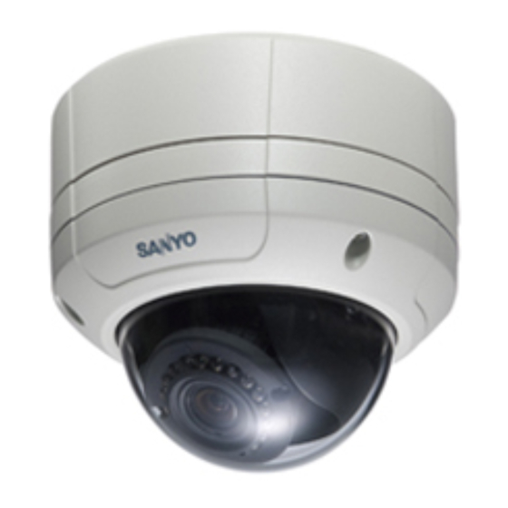
VDC-D1785IRVP
Vandal-resistant IR Dome Camera
Dimensions:mm (inches)
Model Number
VDC-D1785IRVP
Scanning system
PAL standard 625 lines, 50fields/sec.
Image sensor
1/3" Interlace CCD sensor
Number of effective pixels
752(H) x 582(V)
Horizontal resolution
540 TV lines (Typical)
Lens
f=3.7 to 12mm, F1.4, IR lens
Minimum illumination (50IRE)
0.7lx LED-Off, 0.0lx LED-ON
Video/ Monitor output
1.0V p-p (75Ohms, composite)
Video S/N ratio
More than 48dB
Day & Night
True Day/ Night
Backlight compensation
ON/ OFF
White balance
Auto
Auto iris drive
DC
AGC gain
ON/ OFF
Flickerless
ON/ OFF
Gamma correction
0.45
Sync system
Internal
Unshielded Twisted Pair
Passive type
IR LED
18 pcs
IR distance
20m
IR wavelength
850nm
Operating temperature
-10°C to +50°C (14°F to 122°F)
Operating humidity
Less than 90% (no condensation)
Power supply
12VDC+/-10%, 24VAC+/-10%, 50/60Hz
Power consumption
7.0w
Weather Protection class
IP67
Dimensions (Φ x H)
150 x 129mm (5.9" x 5.1")
Weight
Approx. 949g (33.47oz) (Inceiling)
1.Wall/Inceiling Mounting template...1pc
2.Surface-mount adaptor...... .. ....1pc
3.Installation Manual......... . ........1pc
4.Conduit cap.................. .........1pc
5.Fixing screw (P⊕4*31TP)..........4pcs
Accessories
6.Wall plugs............... ..............4pcs
7.Fixing scerw (M4x0.7P x15mm)..3pcs
8.Screwdriver...........................1pc
9.Monitor out cable.....................1pc
0.Hexagonal wrench...................1pc
PRECAUTIONS
■ Do not modify
Do not modify the cabinet and caamera, as it maybe
dangerous and cause of damage to the unit. For repairs,
consult your dealer or an Authorized sanyo Service Center
INSTALLATION
For Inceiling Mount
For Surface Mount
installation
installation
-Inceiling type-
-Surface type-
(A)
(B)
1 Loosen the 3 fixing screws using the supplied hexagonal wrench
and remove the dome cover.
2 Inceiling : Place the supplied "Mounting template for inceiling"
(C)
on the mounting surface, and mark 3 positions shown in.
or
Surface : Place the supplied "Mounting template for surface" on
(# 1)
the mounting surface, and mark 4 positions shown in.
(D)
3 Drill holes at positions as marked and insert the supplied screw
holes in the holes.
4 Cut a hole in the ceilling or the wall for routing the cables.
(E)
5 Pass the power cable, video cable and UTP cable from the
camera unit through the cable hole in the ceilling or the wall.
6 Align the unit mounting holes of the camera unit with the holes
(F)
in the ceilling or the wall.
7 Secure with the supplied mounting screws.
8 Carry out the settings and adjustments for the camera. Refer to
(G)
"CONNECTIONS AND SETTINGS" for camera settings and lens
adjustments.
* When routing the cables on ceiling or wall surface:
Loosen the conduit hole cover fixing screw on the back of the
camera unit base with the hexagonal wrench, open the cover,
(H)
and pass the connection cables through the conduit hole.
HINT
(#1) Press the grip portion to remove the mask before adjustment.
Degree of protection: IP67
67
67
IP67
67
Taiwan
Taiwan
Advertisement
Table of Contents

Related Manuals for Sanyo VDC-D1785IRVP


Summary of Contents for Sanyo VDC-D1785IRVP
- Page 1 PRECAUTIONS ■ Do not modify Do not modify the cabinet and caamera, as it maybe dangerous and cause of damage to the unit. For repairs, consult your dealer or an Authorized sanyo Service Center INSTALLATION For Inceiling Mount installation Model Number...
- Page 2 Connect White: + Black : - 12VDC/ 24VAC Passive type Check for polarity when using a 12VDC power supply (Polarity does not matter when using a 24VAC power supply). ■ LENS ADJUSTMENT ■ CAMERA SETTING Rotation Adjustment Tilt Adjustment Focus lever & lock Zoom lever &...
Need help?
Do you have a question about the VDC-D1785IRVP and is the answer not in the manual?
Questions and answers