Advertisement
2. QUICK START
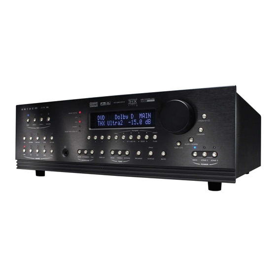
The AVM 30 is a very sophisticated component, providing a multitude of features and connection options,
while providing easy intuitive setup and operation. With your AVM 30 in front of you, browse through the
illustrations in this section to see several quick system hookup options. It's as simple as following the lines
in the connection diagrams to and from each component.
All of these quick system hookup examples work with the Factory Default settings; none require the
Setup Menu. Just 'plug & play'! However, references to the Setup Menu section are included to make
you aware of the tremendous versatility of the AVM 30.
For the best sound possible you will still have to calibrate your system in the Setup as outlined in section 7.
Please do not overlook this important system calibration procedure.
2.1
To connect a CD player, DVD player, TV, VCR, amplifier(s), and powered subwoofer to the AVM 30:
Note: For this Quick start setup section, you will only need to connect either the Composite or S-Video
Reconnect the power to all components and turn them on. To turn on the AVM 30, move the switch on the
rear panel to the 'on' position and then press the POWER – MAIN button on the front panel.
3
QUICK START GUIDE – Before you start, make sure all components are unplugged.
connections referred to in the following diagrams. Use the S-Video connections wherever
possible for the better video quality.
• CD Player to AVM 30 – see diagram in section 2.2.1
Connect the L/R audio output of the CD player to Analog Audio-In/CD on the AVM 30.
• DVD Player to AVM 30 – see diagram in section 2.2.2
Video: Connect the player's composite video out to Composite Video-In/DVD on the AVM 30.
Audio: Connect the player's digital audio output to Digital Audio-In/DVD on the AVM 30.
Make sure your DVD player's setup menu is configured to output Dolby Digital and DTS material
as "Bitstream", not "PCM", otherwise 5.1-channel soundtracks will be turned into 2.0 channels!
• AVM 30 to TV – see diagrams in sections 2.2.2 and 2.2.3
Video: Connect Composite Video-Out/MAIN on the AVM 30 to the TV's composite video input.
Audio: Connect the L/R audio output of the TV to Analog Audio-In/TV on the AVM 30.
• VCR to AVM 30 – see diagram in section 2.2.3
Video: Connect the VCR's composite video output to Composite Video-In/VCR on the AVM 30.
To Record: Connect Composite Video-Out/VCR to the VCR's composite video input.
Audio: Connect the L/R audio output of the VCR to Analog Audio-In/VCR on the AVM 30.
To Record: Connect Analog Audio-Out/VCR to the L/R audio input of the VCR.
• AVM 30 to Amplifier(s) – see diagrams in sections 2.2.4 and 2.2.5
From the AVM 30, connect Front-L, Front-R, Ctr1, Sur-L, Sur-R, Rear-L, and Rear-R Analog
Audio-Out to the Front-L, Front-R, Center, Sur-L, Sur-R, Rear-L, and Rear-R inputs of the
power amplifier(s). Follow the amplifier's operating manual for connecting the speakers.
• AVM 30 to Powered Subwoofer – see diagrams in sections 2.2.4 and 2.2.5
Connect Analog Audio-Out/Sub1 to the subwoofer's line/low level input.
Advertisement
Table of Contents

Related Manuals for Anthem AVM 30


Summary of Contents for Anthem AVM 30
- Page 1 Connect Analog Audio-Out/Sub1 to the subwoofer’s line/low level input. Reconnect the power to all components and turn them on. To turn on the AVM 30, move the switch on the rear panel to the ‘on’ position and then press the POWER – MAIN button on the front panel.
- Page 2 Note about Digital and Analog Inputs: • You can change any input to Digital or Analog. Digital inputs use the AVM 30’s high-end digital to analog converters and can be changed from RCA to Toslink or XLR connection. Analog inputs can be set to Digital Signal Processing for bass management, bass/treble control, time alignment, and surround modes, or Direct to bypass all digital stages.
- Page 3 2. QUICK START continued … 2.2.1 CD Player to AVM 30 CD Player Track 1 CD Player Audio Out EJECT © © © ©...
- Page 4 2. QUICK START continued … 2.2.2 DVD Player and TV to AVM 30 Rear Panel of TV Audio CATV Composite Video In Component Video In Vari Fixed S-Video In Note: For info on Component Video use, see sections 4.3, 7.4.5, and 7.4.10 ©...
- Page 5 2. QUICK START continued … 2.2.3 VCR and TV to AVM 30 Rear Panel of TV Audio CATV Composite Video In Component Video In Vari Fixed S-Video In EJECT © © © © Audio Video Composite S-Video...
- Page 6 2. QUICK START continued … 2.2.4 AVM 30 to Amplifier and Powered Subwoofer (RCA) Powered Subwoofer Input Level © © © © P V A T R I G G E R S REAR REAR MADE IN CANADA INPUT THIS PRODUCT IS BUILT WITH THE FOLLOWING PATENTS: CDN.
- Page 7 2. QUICK START continued … 2.2.5 AVM 30 to Amplifiers and Powered Subwoofer (XLR) To powered subwoofer © © © © Trigger Setup Suggestion: If it is not necessary to have both amplifiers turned on when stereo sources are playing, set triggers...
- Page 8 2. QUICK START continued … SPEAKER PLACEMENT These illustrations show the typical speaker placement for a 7.1-channel surround system, the ‘.1’ channel being the LFE (Low Frequency Effect). The Front and Center speakers are directed towards the listener from the front, while the Surround speakers are positioned to the sides, and the Rear speakers are positioned behind the listener.
Need help?
Do you have a question about the AVM 30 and is the answer not in the manual?
Questions and answers