Table of Contents
Advertisement
Quick Links
Nebula
Maxon DS-830 Distortion Master
Overview
1
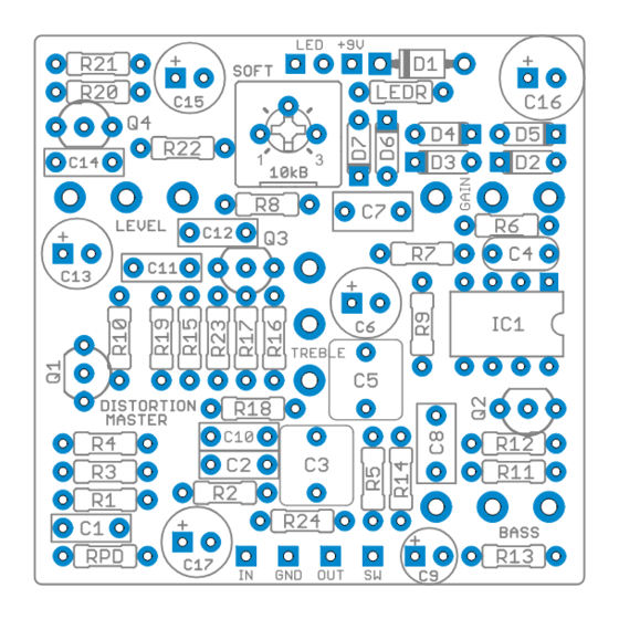
Controls & Usage
• Gain controls the amount of gain from the op amp that is fed through the feedback clipping diodes.
• Level is the output level of the effect.
• Bass allows you to adjust the low-end response of the circuit via a gyrator-based tone control.
• Treble allows you to adjust the high-end response of the circuit, also via a gyrator tone control.
Modifications
This is a tight layout, so you won't find any of the "standard" Aion modifications such as a clipping diode switch.
However, there are extra pads for the soft clipping diodes clipping diodes (D2 through D5) in case you want to
stack two diodes in series—for instance, two 1N914s or one 1N914 and one BAT41 on each side. The stock
unit only uses one in each direction.
For the hard-clipping diodes, I've included the "Soft" trimmer which is on most of my other hard-clipping
circuits. This allows you to put some resistance in series with the hard-clipping diodes which reduces their
effect and softens the hard-clipping somewhat. When turned all the way down, it's fully removed from the
circuit, so I recommend including it.
Any other standard-pinout dual op-amps will work in this circuit as well. Try a TL072 or OPA2104.
Like a Tube Screamer, you can adjust R7 + C5 to change the gain structure and the low-end rolloff frequency.
The stock corner frequency is 408 Hz. Just keep in mind you've got a bass control further along in the circuit so
you can dial out whatever you don't like.
MAXON DS-830 DISTORTION MASTER / NEBULA DISTORTION
3
The Nebula Distortion is a clone of the Maxon DS-380, a
relatively new addition to Maxon's line of pedals but one that
maintains the spirit of their innovations in the 1980s.
Despite being a relative late-comer, the circuit is a very worthy
addition to Maxon's product line and retains the spirit and
character of their classic designs: a JRC4558D op-amp with
feedback-diode clipping like the Tube Screamer, plus some
interesting twist that makes it unique. In this case, it's a two-band
gyrator tonestack (not dissimilar from a Boss HM-2 Heavy Metal)
that offers a great deal more flexibility and imparts a very different
tonal character than the typical amp-like passive tonestack.
Nebula Project Link
1
Advertisement
Table of Contents

Subscribe to Our Youtube Channel
Related Manuals for Aion Electronics Nebula DS-830 Distortion Master

Summary of Contents for Aion Electronics Nebula DS-830 Distortion Master
- Page 1 Nebula Maxon DS-830 Distortion Master Overview Nebula Project Link The Nebula Distortion is a clone of the Maxon DS-380, a relatively new addition to Maxon’s line of pedals but one that maintains the spirit of their innovations in the 1980s. Despite being a relative late-comer, the circuit is a very worthy addition to Maxon’s product line and retains the spirit and character of their classic designs: a JRC4558D op-amp with...
- Page 2 Parts Capacitors Resistors, cont. Semiconductors 100n 2N5457 100k Q2–Q4 2N5088 JRC4558D film 10pF 390R 1N4002 D2, D5 1N914 film 10uF D3–D4 jumper electro 470n 100k D6–D7 1N914 220n 5mm LED 3.3uF 220R electro Potentiometers 100n Gain 250kA 560R Level 100kA 10uF electro Bass...
- Page 3 Schematic MAXON DS-830 DISTORTION MASTER / NEBULA DISTORTION...
- Page 4 General Build Instructions These are general guidelines and explanations for all Aion Electronics DIY projects, so be aware that not everything described below may apply to this particular project. Build Order When putting together the PCB, it’s recommended that you do not yet solder any of the enclosure-mounted control components (pots and switches) to the board.
- Page 5 Drilling & Placement Print this page and have an adult cut out the drilling template below for you. Tape it to the enclosure to secure it while drilling. Note that the holes are shown slightly smaller than they need to be, so drill out the holes as shown and then step up until they are the correct size for the components.
- Page 6 Standard Wiring Diagram This diagram shows standard true-bypass wiring with a 3PDT switch. When the switch is off, the input of the circuit is grounded and the input jack is connected directly to the output jack. The SW pad is the cathode connection for the LED.
Need help?
Do you have a question about the Nebula DS-830 Distortion Master and is the answer not in the manual?
Questions and answers