Advertisement
Quick Links
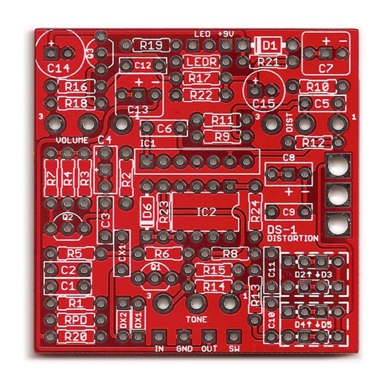
Comet Distortion
BOSS DS-1 Distortion
Overview
Controls & Usage
The DS-1's controls are standard drive/distortion controls:
• Drive controls the amount of gain from the op amp that is fed into the diode clipping stage.
• Tone is similar to the Big Muff tone control, panning between a bass and treble emphasis.
• Volume controls the overall output.
Modifications & Experimentation
The Clipping switch mod allows you to set up a second set of diodes to toggle back and forth from stock.
Extra pads have been provided so you can stack two diodes in a row if desired. (The middle two pads are
connected in each diode.) If you use a SPDT center-off switch, the middle position becomes a diode lift mode,
but you can also use a regular SPDT if you don't care about this.
The pre-1994 version uses a TA7136P single-in-line op amp. The revised post-1994 circuit uses a poor-
quality dual op amp, and one of the most common modifications is to switch this out with a better op amp
such as an OPA2134 or JRC4558. However, this is a tricky mod and requires an awkward breakout adapter,
since the dual op amp is also a single-in-line style. I elected to build the layout around a DIP8 dual op amp to
accommodate. (Ironically, then, the only version of the DS-1 that you can't build with this PCB is the one you
can buy for $40 from any music store today.)
Due to the similarity between the DS-1's pregain stage and the Big Muff's clipping gain stages, this PCB has
space for a few extra diodes and capacitors to convert this stage to Big Muff specs. (Thanks to Build Your Own
Clone for this mod!) This will tighten up the bass and change the distortion character.
DS-1 DISTORTION / COMET DISTORTION
The Comet Distortion project is a clone of the classic
orange BOSS DS-1 Distortion, in continuous production
since 1978. The circuit has a few different things going
on—the pregain and tone sections are very similar to the
Big Muff, while the diode-to-ground hard clipping is similar
to circuits like the Distortion+.
The DS-1 had a major circuit revision in 1994 that
dropped the original single op-amp in favor of a dual,
along with some other changes to accompany the new
op-amp. The original "Made in Japan" version is very
well-regarded, while the revised "post-1994" version is
not as much. However, it is one of the most frequently-
modified pedals out there, with great mods available from
Keeley, Analogman and Monte Allums. The circuit itself
is a great one—the BOSS pedal just suffers from cheap
components.
The Comet Distortion will allow you to build either the
pre- or post-1994 versions of the circuit, as well as
incorporating most of the popular modifications.
Comet Project Link
1
Advertisement

Subscribe to Our Youtube Channel
Related Manuals for Aion Electronics Comet Distortion

Summary of Contents for Aion Electronics Comet Distortion
- Page 1 BOSS DS-1 Distortion Overview Comet Project Link The Comet Distortion project is a clone of the classic orange BOSS DS-1 Distortion, in continuous production since 1978. The circuit has a few different things going on—the pregain and tone sections are very similar to the Big Muff, while the diode-to-ground hard clipping is similar to circuits like the Distortion+.
- Page 2 Small Bear to insulate the back of the pots from the board and prevent shorts. If you don’t use these, use some electrical tape or cardboard to act as insulation. The right-angle pots will make direct contact with the solder pads otherwise. DS-1 DISTORTION / COMET DISTORTION...
- Page 3 Big Muff clipping stage. To do this, put a 100n cap in CX1 and two 1N914s for DX1 and DX2. This will clip the signal before it gets amplified by the op amp. DS-1 DISTORTION / COMET DISTORTION...
- Page 4 Schematic (pre-1994 values) DS-1 DISTORTION / COMET DISTORTION...
- Page 5 General Build Instructions These are general guidelines and explanations for all Aion Electronics DIY projects, so be aware that not everything described below may apply to this particular project. Build Order When putting together the PCB, it’s recommended that you do not yet solder any of the enclosure-mounted control components (pots and switches) to the board.
-
Page 6: Parts Used
Note that the holes are shown slightly smaller than they need to be, so drill out the holes as shown and then step up until they are the correct size for the components. Hammond 1590B (bottom/inside view) Parts Used • Switchcraft #111A enclosed jacks • Kobiconn-style DC jack with internal nut DS-1 DISTORTION / COMET DISTORTION... -
Page 7: Standard Wiring Diagram
(In other words: you don’t have to go out of your way to advertise the fact that you use these PCBs, but please don’t go out of your way to hide it. The guitar effects pedal industry needs more transparency, not less!) DS-1 DISTORTION / COMET DISTORTION...
Need help?
Do you have a question about the Comet Distortion and is the answer not in the manual?
Questions and answers