Table of Contents
Advertisement
Original Instruction - English Version
OVERHAUL MANUAL
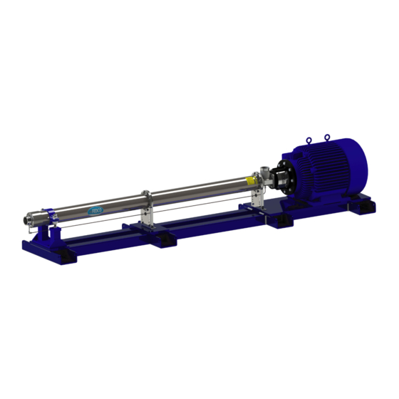
MSS™
MULTI-STAGE SEAWATER
HIGH PRESSURE PUMPS
Models: MSS-15 ● MSS-20 ● MSS-30 ● MSS-50 ● MSS-70
MSS-40 ● MSS-55 ● MSS-75
www.fedco-usa.com
ONE COPY OF THIS MANUAL MUST REMAIN WITH THE EQUIPMENT AT ALL TIMES
MSS 15-75 Overhaul Manual, 02-015-XXXXXX-1
Advertisement
Table of Contents

Related Manuals for FEDCO MSS Series

Summary of Contents for FEDCO MSS Series
- Page 1 MSS™ MULTI-STAGE SEAWATER HIGH PRESSURE PUMPS Models: MSS-15 ● MSS-20 ● MSS-30 ● MSS-50 ● MSS-70 MSS-40 ● MSS-55 ● MSS-75 www.fedco-usa.com ONE COPY OF THIS MANUAL MUST REMAIN WITH THE EQUIPMENT AT ALL TIMES MSS 15-75 Overhaul Manual, 02-015-XXXXXX-1...
- Page 2 FEDCO Certifications ISO 9001 and ISO 14001: FEDCO has adopted the ISO 9001 standard to define and develop our Quality Manage- ment System (QMS.) The QMS allows FEDCO to better serve our customers’ needs through continuous improvement of the quality, delivery, and efficiency of our products.
- Page 3 P.O. Box 282102 Fax: 734-241-5173 Dubai, United Arab Emirates Email: sales@fedco-usa.com Telephone: +971 (0) 4-824 5303 Fax: +971 (0) 4-824 5303 Email: sales@fedco-usa.com www.fedco-usa.com For patent coverage visit patent.fedco-usa.com © Copyright 2022 Fluid Equipment Development Company | www.fedco-usa.com - 3 -...
-
Page 4: Table Of Contents
Specifications ..........58 Cleaning ............ 58 Inspection..........58 Fastener Torque Specifications ....59 Pump Alignment Specifications ....59 Balance Disc Specifications ...... 59 Lubricants and Compounds ...... 59 Notes.............60 © Copyright 2022 Fluid Equipment Development Company | www.fedco-usa.com - 4 -... -
Page 7: Warnings And Safety Precautions
OR DEATH if instructions are not followed properly. PUNCTURE Hazards which are NOT IMMEDIATELY ACCESSIBLE and can HAZARD RESULT IN SEVERE PERSONAL INJURY OR DEATH if instruc- tions are not followed properly. © Copyright 2022 Fluid Equipment Development Company | www.fedco-usa.com - 7 -... -
Page 8: User Health And Safety
Refer to the motor nameplate for specific to the equipment or the use of parts not provided by electrical operating information. FEDCO. If there is a question regarding the intend- • Electrical connections must be made by ed use of the equipment, please contact a FEDCO certified electricians in compliance with representative before proceeding. -
Page 9: Pump Overhaul
Coupling guard screws (part of coupling guard) Retaining clip cap screws Coupling guard Lock washer Motor adapter Throttle nipple Motor adapter bolts Throttle nipple O-ring Flexible coupling Bearing drain line © Copyright 2022 Fluid Equipment Development Company | www.fedco-usa.com - 9 -... -
Page 10: Mss Pump Internal Components (Mss-15/20/30/50/70)
HP shaft bushing (if equipped) Series spacer (two shell pumps only) HP shaft bushing O-ring (if equipped) Series flange O-ring HPSC O-ring (if equipped) Discharge ring HPSC retaining ring (if equipped) © Copyright 2022 Fluid Equipment Development Company | www.fedco-usa.com - 10 -... -
Page 11: Mss Pump Internal Components (Mss-40/55/75)
Impeller HP shaft bushing (if equipped) Split cone HP shaft bushing O-ring (if equipped) Series flange O-ring HPSC O-ring (if equipped) Discharge ring HPSC retaining ring (if equipped) © Copyright 2022 Fluid Equipment Development Company | www.fedco-usa.com - 11 -... -
Page 12: Mechanical Seal Removal
3. Loosen the screws and remove the coupling Figure 6 - Coupling Guard Removal guards. 4. Remove the anchor bolts and washers from shell support bracket(s). Figure 7 - Support Bracket Anchor Bolt Removal © Copyright 2022 Fluid Equipment Development Company | www.fedco-usa.com - 12 -... - Page 13 30.5 cm (12 inches) away from motor. NOTES: Make sure to support inlet end of the pump on support bracket(s). Figure 10 - Separating Pump From Motor © Copyright 2022 Fluid Equipment Development Company | www.fedco-usa.com - 13 -...
- Page 14 Figure 12 - Removing Motor Adapter and Shipping Plug 10. Remove the inlet retaining ring from the inlet housing. Figure 13 - Removing Inlet Retaining Ring © Copyright 2022 Fluid Equipment Development Company | www.fedco-usa.com - 14 -...
-
Page 15: Mechanical Seal Installation
Shaft and Bore Mechanical Seal Installation 1. Install the new shaft washer onto pump shaft and slide the washer against the shaft retaining ring. Figure 16 - Installing Shaft Washer © Copyright 2022 Fluid Equipment Development Company | www.fedco-usa.com - 15 -... - Page 16 Figure 18 - Installing Inlet Retaining Ring 4. Install the shipping plug into the motor adapter seat. Figure 19 - Installing Shipping Plug © Copyright 2022 Fluid Equipment Development Company | www.fedco-usa.com - 16 -...
- Page 17 NOTES: Make sure pump key shaft does not jam or fall out during installation. 8. Refer to from the Final Pump Alignment Installation/ Operation Manual. Figure 22 - Attaching Pump to Motor © Copyright 2022 Fluid Equipment Development Company | www.fedco-usa.com - 17 -...
-
Page 18: Hpsc Mechanical Seal Removal
1. Perform Steps 1 through 7 in Mechanical removal procedure. Seal Removal 2. Disconnect the drain line and vent line(s) Figure 24 - Disconnecting Drain/ Vent Lines from the high pressure seal carrier. © Copyright 2022 Fluid Equipment Development Company | www.fedco-usa.com - 18 -... - Page 19 Figure 26 - Removing Motor Adapter and Shipping Plug 5. Remove the high pressure seal carrier from the inlet housing. Figure 27 - Removing High Pressure Seal Carrier © Copyright 2022 Fluid Equipment Development Company | www.fedco-usa.com - 19 -...
- Page 20 NOTES: The graphite shaft sleeve retaining ring does not need to be removed unless it is distorted or corroded and needs replacement. Figure 30 - Removing Graphite Sleeve Components © Copyright 2022 Fluid Equipment Development Company | www.fedco-usa.com - 20 -...
-
Page 21: Hpsc Mechanical Seal Installation
Figure 32 - Installing Graphite Sleeve Components 2. Install the new high pressure seal carrier O- ring. Figure 33 - Installing New High Pressure Seal Carrier O-ring © Copyright 2022 Fluid Equipment Development Company | www.fedco-usa.com - 21 -... - Page 22 Figure 36 - Installing Shipping Plug © Copyright 2022 Fluid Equipment Development Company | www.fedco-usa.com - 22 -...
- Page 23 9. Perform Steps 6, 7 and 8 in Mechanical Seal procedure in the previous sec- Installation Figure 39 - Installing Drain/ Vent Lines tion. © Copyright 2022 Fluid Equipment Development Company | www.fedco-usa.com - 23 -...
-
Page 24: Shaft Position Sensor Removal
1. Disconnect the shaft position sensor from its power source. 2. Loosen the adjustment locknut at the top of the spacer plate. Figure 41 - Loosening Adjustment Locknut © Copyright 2022 Fluid Equipment Development Company | www.fedco-usa.com - 24 -... -
Page 25: Shaft Position Sensor Installation
2. Loosely thread the shaft position sensor into the spacer plate. Figure 44 - Installing Shaft Position Sensor © Copyright 2022 Fluid Equipment Development Company | www.fedco-usa.com - 25 -... - Page 26 5. Once the sensor is properly adjusted, dis- connect the sensor from the temporary power supply and permanently connect the sensor to the VFD. Figure 46 - Tightening Adjustment Locknut © Copyright 2022 Fluid Equipment Development Company | www.fedco-usa.com - 26 -...
- Page 27 Discharge housing O-ring Balance disc washer Discharge housing Bearing carrier Cavity cover O-ring Throttle nipple O-ring Cavity cover Throttle nipple Pump shaft nut Figure 47 - Balance Disc Components © Copyright 2022 Fluid Equipment Development Company | www.fedco-usa.com - 27 -...
-
Page 28: Balance Disc Removal
4. Remove the throttle nipple from the dis- charge housing. Figure 49 - Removing Throttle Nipple 5. Remove the throttle nipple O-ring from the discharge housing. Figure 50 - Removing Throttle Nipple O-Ring © Copyright 2022 Fluid Equipment Development Company | www.fedco-usa.com - 28 -... - Page 29 O-ring from the end shell. Figure 52 - Removing Discharge Housing 8. Remove the cavity cover with O-ring. Figure 53 - Removing Cavity Cover © Copyright 2022 Fluid Equipment Development Company | www.fedco-usa.com - 29 -...
- Page 30 OR CHAIN WRENCH Figure 55 - Securing Pump Shaft 11. Remove the shaft nut, lock washer and washer from the pump shaft. Figure 56 - Removing Shaft Nut and Washers © Copyright 2022 Fluid Equipment Development Company | www.fedco-usa.com - 30 -...
- Page 31 Figure 57 - Removing Bearing Carrier and Balance Disc 13. Remove the balance disc key and washer from the pump shaft. Figure 58 - Removing Balance Disc Washer and Key © Copyright 2022 Fluid Equipment Development Company | www.fedco-usa.com - 31 -...
-
Page 32: Balance Disc Inspection
(0.51”) Figure 60 - Measuring Balance Disc MSS-75 3. Inspect the bearing carrier for unusual wear or scoring and replace if necessary. Figure 61 - Inspecting Bearing Carrier © Copyright 2022 Fluid Equipment Development Company | www.fedco-usa.com - 32 -... -
Page 33: Balance Disc Installation
Washer 3. Install the balance disc into bearing carrier. NOTES: Make sure the balance disc is firmly seated in the bearing carrier. Figure 64 - Installing Balance Disc © Copyright 2022 Fluid Equipment Development Company | www.fedco-usa.com - 33 -... - Page 34 6. Locate the discharge housing anti-rotation pin on the bearing carrier and note the loca- tion of the discharge housing anti-rotation pin hole. Figure 67 - Discharge Housing Alignment Pin © Copyright 2022 Fluid Equipment Development Company | www.fedco-usa.com - 34 -...
- Page 35 10. Install the retention clips, lock washers and cap screws. Tighten to torque value speci- fied in the Fastener Torque Specifications section of this manual. Figure 70 - Install Discharge Housing Retaining Clips © Copyright 2022 Fluid Equipment Development Company | www.fedco-usa.com - 35 -...
- Page 36 Figure 72 - Taping Throttle Nipple 13. Gently insert throttle nipple using a clock- wise twisting motion to prevent dislodging the throttle nipple O-ring. Figure 73 - Installing Throttle Nipple © Copyright 2022 Fluid Equipment Development Company | www.fedco-usa.com - 36 -...
- Page 37 Figure 74 - Connecting Drain Line 15. Remove the strap or chain wrench and install the coupling guards and tighten the screws. Figure 75 - Installing Coupling Guards © Copyright 2022 Fluid Equipment Development Company | www.fedco-usa.com - 37 -...
-
Page 38: Stage Replacement (Mss-15/20/30/50/70)
TOOLS REQUIRED: Gage block, Shaft wrench or Strap wrench, Torque wrench. NOTES: Consult a FEDCO representative for all information regarding assembly specifications. ELECTRICAL HAZARD Make sure to disconnect the power supply to the motor before carrying out component replace- ment procedures. - Page 39 5. Remove the motor adapter bolts and wash- ers. Figure 79 - Motor Adapter Bolt Removal 6. Remove the nuts and the top cradle from the precision leveling foot. Figure 80 - Top Cradle Removal © Copyright 2022 Fluid Equipment Development Company | www.fedco-usa.com - 39 -...
- Page 40 13. Using proper lifting methods safely lift unit from base and place on flat surface in the vertical position. Figure 83 - Lifting Unit From Mounting Position © Copyright 2022 Fluid Equipment Development Company | www.fedco-usa.com - 40 -...
- Page 41 These are Figure 86 - End Shell Bolt Removal considered part of the shell assembly and will come out when shell is removed. © Copyright 2022 Fluid Equipment Development Company | www.fedco-usa.com - 41 -...
- Page 42 These are Figure 89 - Series Shell Removal considered part of the shell assembly and will come out when shell is removed. © Copyright 2022 Fluid Equipment Development Company | www.fedco-usa.com - 42 -...
- Page 43 Install the retaining ring into the split collar sleeve. d. Install the mechanical seal retaining ring onto the pump shaft. Figure 92 - Shaft Collar Installation NOTES: Only remove pump shaft/ mechanical seal if necessary. © Copyright 2022 Fluid Equipment Development Company | www.fedco-usa.com - 43 -...
- Page 44 MSS-50/70 Pumps: Install the first diffuser bowl onto the inlet ring. NOTES: Verify diffuser bushings have been pre-installed before assembly. Figure 95 - Starting Stage Installation © Copyright 2022 Fluid Equipment Development Company | www.fedco-usa.com - 44 -...
- Page 45 Fastener Torque Specifi- section of this manual. cations NOTES: Make sure there is no gap between Figure 98 - Series Shell Installation flanges after tightening bolts. © Copyright 2022 Fluid Equipment Development Company | www.fedco-usa.com - 45 -...
- Page 46 On some installations, this end spacer may be engraved to help distin- guish it from standard stock spacers. Figure 101 - End Spacer Installation © Copyright 2022 Fluid Equipment Development Company | www.fedco-usa.com - 46 -...
- Page 47 18. Gently insert throttle nipple using a clock- wise twisting motion to prevent dislodging the throttle nipple O-ring. 19. Reconnect the bearing drain line to the throttle nipple. Figure 104 - Installing the Drain Line © Copyright 2022 Fluid Equipment Development Company | www.fedco-usa.com - 47 -...
- Page 48 Mechanical Seal Installation of this manual. 20. Refer to the Section Final Pump Alignment of the for pump re- MSS Installation Manual alignment procedures. Figure 105 - Final Pump Alignment © Copyright 2022 Fluid Equipment Development Company | www.fedco-usa.com - 48 -...
-
Page 49: Stage Replacement (Mss-40/55/75)
Stage Replacement (MSS-40/55/75) TOOLS REQUIRED: Gage block, Shaft wrench or Strap wrench, Torque wrench. NOTES: Consult a FEDCO representative for all information regarding assembly specifications. ELECTRICAL HAZARD Make sure to disconnect the power supply to the motor before carrying out component replace- ment procedures. - Page 50 Single Shell Pumps: Skip this step. Two Shell Pumps: Remove the series shell inlet ring. Remove the series shell O-ring. Figure 110 - Inlet Ring Removal (Series Shell) © Copyright 2022 Fluid Equipment Development Company | www.fedco-usa.com - 50 -...
- Page 51 1. Remove, inspect, and replace the shaft if necessary. a. Install the mechanical seal retaining ring onto the pump shaft. NOTES: Only remove pump shaft/ mechanical seal if necessary. Figure 113 - Shaft Installation © Copyright 2022 Fluid Equipment Development Company | www.fedco-usa.com - 51 -...
- Page 52 3. Apply anti-seize compound to the split cone threads Anti-Seize 4. Install the split cone into the impeller 5. Loosely install the split cone nut onto the split cone Figure 115 - Impeller Assembly © Copyright 2022 Fluid Equipment Development Company | www.fedco-usa.com - 52 -...
- Page 53 15. Grasp impeller to prevent rotation and tighten split cone nut to torque value speci- fied in the Fastener Torque Specifications section of this manual. Figure 119 - Impeller Installation © Copyright 2022 Fluid Equipment Development Company | www.fedco-usa.com - 53 -...
- Page 54 Fastener Torque Specifi- section of this manual. cations NOTES: Make sure there is no gap between Figure 122 - Series Shell Installation flanges after tightening bolts. © Copyright 2022 Fluid Equipment Development Company | www.fedco-usa.com - 54 -...
- Page 55 Figure 124 - Stage Assembly 22. Install the discharge ring onto the last dif- fuser bowl. Figure 125 - Discharge Ring Installation © Copyright 2022 Fluid Equipment Development Company | www.fedco-usa.com - 55 -...
- Page 56 27. Install the shell bolts connecting to the shell support brackets and re-install the drain line to the inlet. Figure 128 - Lowering Unit Into Mounting Position © Copyright 2022 Fluid Equipment Development Company | www.fedco-usa.com - 56 -...
- Page 57 32. Refer to the Section Final Pump Alignment of the for pump re- MSS Installation Manual alignment procedures. Figure 130 - Final Pump Alignment © Copyright 2022 Fluid Equipment Development Company | www.fedco-usa.com - 57 -...
-
Page 58: Specifications
Protect nameplate integrity. Use considerable caution when cleaning. Do not use products that may damage painted or engraved surfac- es. FEDCO recommends soap and fresh water for cleaning nameplate surfaces. © Copyright 2022 Fluid Equipment Development Company | www.fedco-usa.com - 58 -... -
Page 59: Fastener Torque Specifications
MSS-15 through MSS-75 13.5 mm (0.531") 13.0 mm (0.511") Lubricants and Compounds Lubricant Standard Glycerine or fresh water with soap ASTM D1257 Anti-seize compound Compliant with specific system © Copyright 2022 Fluid Equipment Development Company | www.fedco-usa.com - 59 -... -
Page 60: Notes
_____________________________________________________________________________ _____________________________________________________________________________ _____________________________________________________________________________ _____________________________________________________________________________ _____________________________________________________________________________ _____________________________________________________________________________ _____________________________________________________________________________ _____________________________________________________________________________ _____________________________________________________________________________ _____________________________________________________________________________ _____________________________________________________________________________ _____________________________________________________________________________ _____________________________________________________________________________ _____________________________________________________________________________ _____________________________________________________________________________ _____________________________________________________________________________ _____________________________________________________________________________ _____________________________________________________________________________ _____________________________________________________________________________ _____________________________________________________________________________ _____________________________________________________________________________ _____________________________________________________________________________ _____________________________________________________________________________ _____________________________________________________________________________ _____________________________________________________________________________ _____________________________________________________________________________ _____________________________________________________________________________ _____________________________________________________________________________ © Copyright 2022 Fluid Equipment Development Company | www.fedco-usa.com - 60 -... - Page 61 Street 2, Dubai Invest Park 1 sales@fedco-usa.com Telephone: +1 (734) 241-3935 P.O. Box 282102 Fax: 734-241-5173 Dubai, United Arab Emirates Email: Telephone: sales@fedco-usa.com +971 (0) 4-824 5303 Fax: +971 (0) 4-824 5303 Email: sales@fedco-usa.com FEDCO Sales Office Service Center Revised January 26, 2022 2:16 PM...
Need help?
Do you have a question about the MSS Series and is the answer not in the manual?
Questions and answers