Table of Contents
Advertisement
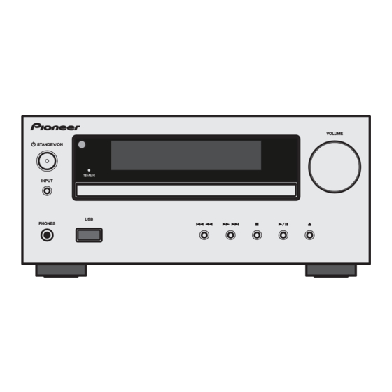
CD Receiver System
X-HM20-K
X-HM20-S
X-HM10-K
X-HM10-S
THIS MANUAL IS APPLICABLE TO THE FOLLOWING MODEL(S) AND TYPE(S).
Model
Type
X-HM20-K
SYXJC8
X-HM20-S
SYXJC8
X-HM10-K
SYXJC8
X-HM10-S
SYXJC8
PIONEER CORPORATION
PIONEER ELECTRONICS (USA) INC. P.O. Box 1760, Long Beach, CA 90801-1760, U.S.A.
PIONEER EUROPE NV Haven 1087, Keetberglaan 1, 9120 Melsele, Belgium
PIONEER ELECTRONICS ASIACENTRE PTE. LTD. 253 Alexandra Road, #04-01, Singapore 159936
PIONEER CORPORATION
Power Requirement
AC 220 V to 240 V
AC 220 V to 240 V
AC 220 V to 240 V
AC 220 V to 240 V
1-1, Shin-ogura, Saiwai-ku, Kawasaki-shi, Kanagawa 212-0031, Japan
2011
X-HM20-K
Serial No.
&&&&######YY
&&&&######YY
&&&&######YY
&&&&######YY
K-IZV SEPT.
ORDER NO.
RRV4220
Remarks
YY: Europe
YY: Europe
YY: Europe
YY: Europe
2011 Printed in Japan
Advertisement
Table of Contents

Related Manuals for Pioneer X-HM20-K


Summary of Contents for Pioneer X-HM20-K
- Page 1 PIONEER CORPORATION 1-1, Shin-ogura, Saiwai-ku, Kawasaki-shi, Kanagawa 212-0031, Japan PIONEER ELECTRONICS (USA) INC. P.O. Box 1760, Long Beach, CA 90801-1760, U.S.A. PIONEER EUROPE NV Haven 1087, Keetberglaan 1, 9120 Melsele, Belgium PIONEER ELECTRONICS ASIACENTRE PTE. LTD. 253 Alexandra Road, #04-01, Singapore 159936...
-
Page 2: Safety Information
Health & Safety Code Section 25249.6 - Proposition 65 IMPORTANT Laser Pickup specifications and Laser characteristics THIS PIONEER APPARATUS CONTAINS For CD Wave length (typ) : 790 nm LASER OF CLASS 1. Operation output : 4 mW CW, Class 1... -
Page 3: Table Of Contents
11. PCB CONNECTION DIAGRAM ............................50 11.1 MAIN and iPOD PCB ASSYS............................. 50 11.2 DISPLAY and KEY-SWITCH PCB ASSYS ......................... 54 11.3 RADIO PCB ASSY ..............................56 11.4 HEADPHONE and USB PCB ASSYS ........................57 11.5 POWER PCB ASSY ..............................58 X-HM20-K... -
Page 4: Service Precautions
• Parts numbers of lead-free solder: GYP1006 1.0 in dia. GYP1007 0.6 in dia. GYP1008 0.3 in dia. 1.2 WHEN REPLACING CD MECHA UNIT It is necessary to remove the soldering on the short circuit point after connecting the flexible cable. Short circuit point X-HM20-K... -
Page 5: Specifications
2. SPECIFICATIONS As part of our policy of continuous improvement, g USB PIONEER reserves the right to make design and specification changes for product improvement without USB host interface k Complies with USB 1.1 (Full prior notice. The performance specification figures Speed)/2.0 Mass Storage... -
Page 6: Basic Items For Service
92L28700220301 1..DISPLAY PCB ASSY (X-HM10) 92L36500101010 1..LOADER ASSY 92L5150020071T 1..RADIO PCB ASSY (X-HM20) 92L36400201010 1..RADIO PCB ASSY (X-HM10) 92L36400101010 1..HEADPHONE PCB ASSY (X-HM20) 92L37100201011 1..HEADPHONE PCB ASSY (X-HM10) 92L37100101011 1..USB PCB ASSY (X-HM20) 92L36900201011 1..USB PCB ASSY (X-HM10) 92L36900101011 X-HM20-K... -
Page 7: Jigs List
3.2 JIGS LIST Lubricants and Glues List Name Part No. Remarks Adhesive (No. 1600B) GYL1007 Refer to "7. DISASSEMBLY". X-HM20-K... -
Page 8: Block Diagram
4. BLOCK DIAGRAM 4.1 OVERALL WIRING DIAGRAM RADIO PCB ASSY (X-HM20: 92L36400201010) (X-HM10: 92L36400101010) HEADPHONE PCB ASSY (X-HM20: 92L37100201011) (X-HM10: 92L37100101011) 1/7- MAIN PCB ASSY (X-HM20: 92L36100 (X-HM10: 92L36100 USB PCB ASSY (X-HM20: 92L36900201011) (X-HM10: 92L36900101011) X-HM20-K... - Page 9 : The power supply is shown with the marked box. DISPLAY PCB ASSY (X-HM20: 92L36500201010) (X-HM20 ONLY) (X-HM10: 92L36500101010) iPOD PCB ASSY (92L36600201010) 1/7- POWER PCB ASSY CB ASSY (X-HM20: 92L36800201010) 0: 92L36100201011) (X-HM10: 92L36800101010) 0: 92L36100101011) KEY-SWITCH PCB ASSY (X-HM20: 92L37200201010) (X-HM10: 92L37200101011) X-HM20-K...
-
Page 10: Overall Block Diagram
FL DISPLAY LCD201 ( IC 201) iPOD PCB VOLUME VR POWER ON ASSY (VOL201) DISPLAY PCB ASSY (X-HM20 ONLY) FUNCTION SCN802(4P) SCN801(6P) KEY BUTTON PLAY STOP DOWN OPEN/CLOSE USB CONNECTOR HP (JACK801) HEADPHONE USB PCB ASSY KEY-SWITCH PCB ASSY PCB ASSY X-HM20-K... -
Page 11: Diagnosis
4. Is the turntable rotating? U5 (pin 68), U7 (pin 9,10,11,12) Check the Laser power, Focus, Tracking peripheral 5. Is the Laser power, Focus, Tracking circuit OK? circuit. U5 (pin 64, 65, 80), U7 (pin 1 to 4 24 to 27) X-HM20-K... -
Page 12: Protection Circuit
After a shutdown, to turn the unit back on, unplug the AC power cord then plug it back into the AC outlet. 6. SERVICE MODE There is no information to be shown in this chapter. X-HM20-K... -
Page 13: Disassembly
(1) Remove the top cabinet. (See procedure "[1] Top Cabinet".) Top cabinet iPOD PCB Assy (1) Disconnect the one flexible cable and one connectors. (J802, J803) (2) Remove the two screws. (3) Remove the iPOD PCB Assy. J802 J803 • Bottom view X-HM20-K... - Page 14 (9) Remove the front panel section. Volume knob Front panel section (10) Remove the two screws. HEADPHONE PCB Assy (11) Remove the 12 screws. KEY-SWITCH PCB Assy USB PCB Assy (12) Remove the DISPLAY, KEY-SWITCH, HEADPHONE and USB PCB Assemblies. DISPLAY PCB Assy X-HM20-K...
- Page 15 (1) Remove the top cabinet. (See procedure "[1] Top Cabinet".) (1) Remove the five screws. • Rear view MAIN PCB Assy (2) Disconnect the one flexible cable and one connectors. (J1, J6) (3) Remove the RADIO PCB Assy. RADIO PCB Assy X-HM20-K...
- Page 16 (2) Remove the one screw. • Rear view (3) Remove the three screws. POWER PCB Assy (4) Remove the two screws. MAIN PCB Assy (5) Disconnect the two connectors. (J9, J11) (6) Remove the POWER PCB Assy. POWER PCB Assy X-HM20-K...
- Page 17 (1) Disconnect the two flexible cables and five MAIN PCB Assy connectors. (J1, J6, J9, J10, J11, J13, J19) (2) Remove the four screws. (3) Remove the MAIN PCB Assy. (4) Remove the three screws. (5) Remove the LOADER Assy. LOADER Assy X-HM20-K...
- Page 18 • Bottom view Disc tray cover The Application Position of Adhesive X-HM20 ONLY Adhesive (No.1600B) GYL1007 Adhesive (No.1600B) GYL1007 Ferrite core Gasket iPOD PCB Assy RADIO PCB Assy X-HM20-K...
-
Page 19: Each Setting And Adjustment
1. Press INPUT button to "Line in" function. 2. In "Line in" function, short press np button once then long press f(PLAY/PAUSE) button until the software version is displayed. software version display: X-HM20-K/-S → "CD-HM20R Vxxx", X-HM10-K/-S → "CD-HM10R Vxxx" X-HM20-K... -
Page 20: Exploded Views And Parts List
Screws adjacent to b mark on product are used for disassembly. For the applying amount of lubricants or glue, follow the instructions in this manual. (In the case of no amount instructions, apply as you think it appropriate.) 9.1 PACKING SECTION X-HM20 only X-HM20-K... - Page 21 12 Speaker Packing Add See Contrast table (2) 13 Miramat Bag Unit 92L89134045001 14 Packing Case See Contrast table (2) (2) CONTRAST TABLE X-HM20-K/SYXJC8, X-HM20-S/SYXJC8, X-HM10-K/SYXJC8 and X-HM10-S/SYXJC8 are constructed the same except for the following: X-HM20-K X-HM20-S X-HM10-K X-HM10-S Mark...
-
Page 22: Exterior Section
9.2 EXTERIOR SECTION X-HM20-K, X-HM20-S only X-HM20-K... - Page 23 23 FL Holder 92L51500200101 24 iPod Spacer See Contrast table (2) 25 CD Mecha Holder 92L51501510101 (2) CONTRAST TABLE X-HM20-K/SYXJC8, X-HM20-S/SYXJC8, X-HM10-K/SYXJC8 and X-HM10-S/SYXJC8 are constructed the same except for the following: X-HM20-K X-HM20-S X-HM10-K X-HM10-S Mark Symbol and Description...
-
Page 24: Schematic Diagram
A16/SDRAM_UDQM/GPIO2[1] A3/GPIO1[20] A2/GPIO1[19] GPIO A1/GPIO1[18] GPIO0 A0/GPIO1[17] GPIO0 VDD_3V3 PDVDD GPIO A10/GPIO1[27] GPIO A14/SDRAM_BANK1/GPIO1[31] A13/SDRAM_BANK0/GPIO1[30] SDRAM_CS SDRAM_CS/GPIO1[13] SD_RAS A18/SDRAM_RAS/GPIO2[3] SD_CAS A17/SDRAM_CAS/GPIO2[2] R140 +3V3 R141 LOW_VOLTAGE_DET SD_LDQ M +3V3 UART_TX UART_RX 3906 delay 180ms RESET 3904 1,0.22uF 16ms 2,1uF 56ms X-HM20-K... - Page 25 GPIO0[11]/LCD_D7 TUNER_RESET/DAB_1V2_CTL EARPHONE_IN_DET GPIO0[10]/LCD_D6 GPIO0[9]/LCD_D5 TRAY_OUT GPIO0[8]/LCD_D4 LCD_D4 L for USB_3v3 of 5256 On STANDBY_KEY GPIO0[7]/LCD_D3 for Buck H Enable GPIO0[6]/LCD_D2 LCD_D2 LCD_D1 for Standby_LED_CTL GPIO0[5]/LCD_D1 GPIO0[4]/LCD_D0 LCD_D0 for analog_channel_SEL LCD_D0 LCD_D1 LCD_D2 2th Funciton for iPod_POW_CTL +3V3 IRDA X-HM20-K...
-
Page 26: Main Pcb Assy (2/7)
FB33 TUNER/DAB_3V3 R104 100R RDS_DAVN R103 100R GPIO_SDA R101 100R GPIO_SCL 100R TUNER_RESET/DAB_1V2_CTL FB34 REAR_RCA_IN_R RCA_GND FB35 FB36 REAR_RCA_IN_L Q851 3904 CON12_S Note:don't populate 1,In the Tuner:R111,R112,R10,R88 2,In the DAB mode:R101,R103,R104,R8 must be delayed to 100ms when present 3v3 X-HM20-K... - Page 27 VDD_SDRAM OTHER_3V3 X-HM20 ONLY For iPod certification IC901 IPOD_PHONE_CP NC 14 R910 MODE1/SPICS MODE0/CLK 13 GPIO_SDA SDA/SOMI 12 TUNER_RESET/DAB_1V2_CTL RESET SCL/SIMO 11 GPIO_SCL OTHER_3V3 SS8550 Q850 Hold Low for at least 30ms Q851 3904 R864 ANALOG_CH_SEL en present 3v3 X-HM20-K...
-
Page 28: Main Pcb Assy (3/7)
+12V_1A1 12V/1.1A CON8_S FB21 U551 MP1430 LOW_VOLTAGE_DET FB31 MCU_+5V only for 75mA 9 SHIELD 1.22v R132 +3V3 FB37 RELAY_CTL DGND 1117/5V +3V3 A_+5V6 R603 VOUT R601 R131 470R CD/DVD_ON Q601 MMBT 3906 only for DVD model MCU_+5V D601 PMEG2101EA X-HM20-K... - Page 29 VDD_3V3 1482 L501 15uH/3A LC1207CC3TR33 FB12 R504 1.22v VOUT USB5.1V VDD_1V8 USB_5.1V Optional AP2121-1.8V D552 LL4148 +3V3 VOUT 4 STBY MP1430 L502 15uH/4A HIELD R554 1.22v 104P NA/PMEG2101EA +3V3 R604 R603 S8050 Q602 R605 +3V3 MMBT 3906 Q603 S8050 X-HM20-K...
-
Page 30: Main Pcb Assy (4/7)
49.9K 49.9K 3904 IPOD_SEL S1 S0 channels iPad_HW_CHARGE by USB port SGM7222/FSUSB30MUX R810 OTHER_3V3 IPOD_SEL S/L=1 DVD_USB_SEL USB_PORT_D+ HSD1+ HSD2+ HSD1- USB_PORT_D- IPOD_D+ R115 IPOD_D- USB_D+ HSD2- LCD_D2 R113 USB_D- R110 DVD_USB_SEL R117 PIN/FUNCTION DVD_USB IPOD_SEL DVD_USB_SEL Note:IPOD_SEL=USB_HW_CHARGE DVD_USB_SEL=IPOD_HW_CHANGE X-HM20-K... - Page 31 CON10_S IPOD_D+ IPOD_D- IPOD_+5V IPOD_HW_CHARNGE_CTL R807 IPOD_DET ACC_POWER R806 R160 OTHER_3V3 IPOD_5.1V USB_5.1V OTHER_3V3 A_+5V6 7.5V/1.5A MMBT 3906 SHORT_DET IPOD_+5V AP2301GN FB800 IPOD_5.1V IPOD_POW_CTL 3904 R115 IPOD_HW_CHARNGE_CTL R117 TION DVD_USB AUDIO_USB iPod_USB Non_USB/iPod mode DEFAULT _SEL _SEL=USB_HW_CHARGE _SEL=IPOD_HW_CHANGE X-HM20-K...
-
Page 32: Main Pcb Assy (5/7)
150P 470P OUTA OUTB C945 C946 C952 100uF R926 R928 R931 OUT3A 220pF C954 FB910 R956 AA_+5V R955 TDA1308 22uF R953 R954 C960 FB911 C953 220pF R932 R935 R937 OUT4B C947 C948 470P 150P R934 R936 R938 OUT4A AUDIO_IN_AGND X-HM20-K... - Page 33 L903 C915 104P C924 C916 C912 104P R908 C930 C925 R913 18V/4.5A 330p R914 C926 1000uF/25v C918 C942 C943 10UH L904 C931 EARPHONE_R 6MM-D-A 6MM-D-A SOLT-SOLDER SOLT-SOLDER PMEG2101EA FB926 A_+5V6 102P C141 EARPHONE_L C143 102P 100uF FB911 AUDIO_IN_AGND ADC_AGND X-HM20-K...
-
Page 34: Main Pcb Assy (6/7)
GND of FM/Line/headphone Realtime clock chip Rear panel board interface +3V3 don't populate REAR_RCA_L +3V3 LL4148 REAR_RCA_R U895 100R STANDBY_KEY INTB VCC1 7 GPIO_SCL_E 100R 32.768KHz GPIO_SCL OSCI 100R GPIO_SDA_E GPIO_SDA OSCO 5 INTA BL5372 don't popula C895 C898 X-HM20-K... - Page 35 Pitch1.0 don't populate OTHER_3V3 R174 C133 4.7uF LL4148 2.2uF KEY2 R173 C134 4.7uF for AUX_DET 3904 A_+5V6 100K +3V3 AUX_FRONT_L 220R AUX_FRONT_R 7P2.0mm 3904 MMBT 3906 AUDIO_IN_AGND EARPHONE_IN_DET EARPHONE_L 3904 220R EARPHONE_R 10uF oard interface REAR_RCA_IN_L REAR_RCA_IN_R don't populate X-HM20-K...
-
Page 36: Main Pcb Assy (7/7)
DVD_BCLK SE_BCLK SCLK R1 14 R105 DVD_LRCK SE_LRCK WCLK R2 15 R106 DVD_DATA DATA CEQ 16 SE_DATA R129 VDDA2 17 3V3_CDA SE_EF/CVBS_IPOD SCLI VSSA2 18 WCLI OSCO 19 100R OSCI 20 VDDD VSSA3 16.9344MHZ 104P C113 SE_CFLG/DVD_TRIN R135 OTHER_3V3 X-HM20-K... - Page 37 Must be populated all mode R133 CN06P/2.0 R120 3V3_CDD +6V5VCC HOME_SW R128 HOME_SW 3V3_CDA VCC1 VREF FOC- FCS- RAD- TRK- RAD+ TRK+ FOC+ FCS+ C117 104P VREF 3V3_CDA C127 16.9344MHZ 47uF VCC1 DA11 VREF VREF VCC1 CON16_DA11 3V3_CDA R138 X-HM20-K...
-
Page 38: Ipod Pcb Assy (X-Hm20 Only)
ACC_POWER IPOD_DET IPOD_+ DVD_USB_SEL IPOD_HW_CHARGE_CTL IPOD_D- IPOD_D+ IPOD_+5V CON10_S pitch1.25 IPOD_+5V iPod docking subboard connector AGND CON2_S FB23 IPOD_VIDEO CON704 FB22 BLM18BB121SN1 J803 IPOD_+5V Ipod docking subboard 43.2K 75.0K AP2301GN IPOD_D+ 49.9K 49.9K AP2301GN IPOD_D- DVD_USB_SEL IPOD_HW_CHARGE_CTL MMBT 3904 X-HM20-K... - Page 39 IPOD_D- USB_D- DP_ML_LANE1_P USB_VBUS DP_ML_LANE1_N ACCE_IDENTIFY DP_HOT_PLUG_DETECT/ F/W_PWR(FLOATING) R801 100R ACC_POW ACCESSORY_PWR(IPOD_OUTPUT) RESERVED iPod DGND/AUXILIARY_CHANNEL_RETURN DGND/MAIN_LANE1_LINK_RETURN RESERVED ACCE_DETECT S_VIDEO_Y/COMPONENT_PR S_VIDEO_C/COMPONENT_Y IPOD_VIDEO COMPOSITE_VIDEO/PB REMOTE_SENSE LINE_IN_L/DP_AUX_CH_P LINE_IN_R/DP_AUX_CH_N LINE_OUT_L LINE_OUT_R AUDIO/VIDEO_RETURN AGND IPOD_DET DGND R803 100R IPOD_30PIN Band rate:19200 or 57600(+/-2%) W_CHARGE_CTL X-HM20-K...
-
Page 40: Radio Pcb Assy
10.9 RADIO PCB ASSY Only for AM model J803 X-HM20-K... - Page 41 RADIO PCB ASSY (X-HM20: 92L36400201010) (X-HM10: 92L36400101010) X-HM20-K...
-
Page 42: Display Pcb Assy
10.10 DISPLAY PCB ASSY DISPLAY PCB ASSY (X-HM20: 92L36500201010) (X-HM10: 92L36500101010) X-HM20-K... - Page 43 X-HM20-K...
-
Page 44: Key-Switch Pcb Assy
10.11 KEY-SWITCH PCB ASSY KEY-SWITCH PCB ASSY (X-HM20: 92L37200201010) (X-HM10: 92L37200101011) X-HM20-K... -
Page 45: Headphone Pcb Assy
10.12 HEADPHONE PCB ASSY HEADPHONE PCB ASSY (X-HM20: 92L37100201011) (X-HM10: 92L37100101011) X-HM20-K... -
Page 46: Power Pcb Assy
10.13 POWER PCB ASSY Only for DVD model X-HM20-K... - Page 47 POWER PCB ASSY (X-HM20: 92L36800201010) (X-HM10: 92L36800101010) X-HM20-K...
-
Page 48: Usb Pcb Assy
10.14 USB PCB ASSY USB PCB ASSY (X-HM20: 92L36900201011) (X-HM10: 92L36900101011) X-HM20-K... - Page 49 X-HM20-K...
-
Page 50: Pcb Connection Diagram
11. PCB CONNECTION DIAGRAM 11.1 MAIN and iPOD PCB ASSYS SIDE A CD MECHA CON702 UNIT (PICKUP) MAIN PCB ASSY Q851 Q850 U895 IC901 U900 IC13 IC800 U501 U551 Q601 X-HM20-K... - Page 51 SIDE A For further information for respective desti- nations, be sure to check with the sche- matic diagram. SIDE B P.C.Board Chip Part CON401 CON704 iPOD PCB ASSY J803 CON402 Q8 Q10 Q12 CON201 SCN201 X-HM20-K...
- Page 52 SIDE B MAIN PCB ASSY iPOD PCB ASSY J803 X-HM20-K...
- Page 53 SIDE B B ASSY IC795 IC902 Q420 X-HM20-K...
-
Page 54: Display And Key-Switch Pcb Assys
11.2 DISPLAY and KEY-SWITCH PCB ASSYS SIDE A Q201 IR101 IC201 KEY-SWITCH PCB ASSY SIDE B KEY-SWITCH PCB ASSY X-HM20-K... - Page 55 SIDE A IC16 DISPLAY PCB ASSY SCN201 CON201 SIDE B CON201 SCN201 DISPLAY PCB ASSY X-HM20-K...
-
Page 56: Radio Pcb Assy
11.3 RADIO PCB ASSY SIDE A SIDE A RADIO PCB ASSY CON704 CON702 CON701 J803 SIDE B SIDE B RADIO PCB ASSY CON704 CON702 CON701 IC701 X-HM20-K... -
Page 57: Headphone And Usb Pcb Assys
11.4 HEADPHONE and USB PCB ASSYS SIDE A SIDE A HEADPHONE PCB ASSY USB PCB ASSY SCN802 SCN801 SIDE B SIDE B HEADPHONE PCB ASSY USB PCB ASSY SCN802 SCN801 X-HM20-K... -
Page 58: Power Pcb Assy
11.5 POWER PCB ASSY SIDE A SIDE A AC IN JACK401 POWER PCB ASSY IC401 Q401 Q402 IC402 X-HM20-K... - Page 59 SIDE B SIDE B POWER PCB ASSY JACK401 X-HM20-K...
Need help?
Do you have a question about the X-HM20-K and is the answer not in the manual?
Questions and answers
Има червен индикатор който постоянно Пресветва