
Related Manuals for AkuSense RCD-AI100-S Series


Summary of Contents for AkuSense RCD-AI100-S Series
- Page 1 Intelligent code reader RCD-AI100-S Series User Manual Intelligent code reader RCD-AI100-S Series User Manual V2.0...
-
Page 2: Table Of Contents
Intelligent code reader RCD-AI100-S Series User Manual 目录 Chapter 1 Product Introduction ....................4 1.1 Product Description ....................4 1.2 Main Features ......................4 1.3 Appearance ......................4 1.4 Interface and Scatter Definition ................6 1.5 Accessories & Dimensions ..................6 Chapter 2 Equipment installation and operation ..............8... - Page 3 Intelligent code reader RCD-AI100-S Series User Manual 5.5.1 Data Filtering ....................32 5.5.2 Data Processing ................... 34 5.6 Output Configuration ....................36 5.6.1 OUT setting ....................36 5.7 Communication configuration ................. 37 5.7.1 Using the TCPServer protocol ..............37 5.7.2 Using the ModbusTcp protocol ..............38 5.7.3 Using the MC protocol ..................38...
-
Page 4: Chapter 1 Product Introduction
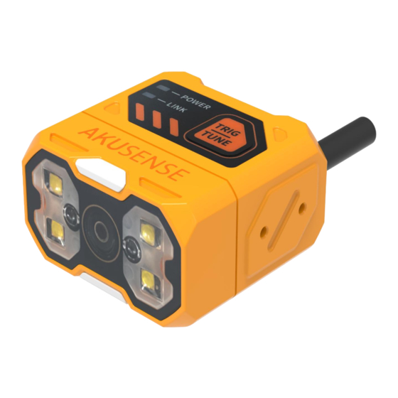
Chapter 1 Product Introduction 1.1 Product Description This manual is applicable to Akusense Intelligent Code Reader RCD-AI100-S series, which can be applied to 3C, food and drug, electronic semiconductor, auto parts and other industries. The device uses sensors and optical components to obtain the image of the object to be measured, and achieves barcode resolution through the device's built-in code reading algorithm. - Page 5 Intelligent code reader RCD-AI100-S Series User Manual image effect Indicates the center of the image for easy Aiming light targeting Image Sensor For image acquisition Green light for normal operation of Power indicator equipment, no light for operation Green light strobe when the network...
-
Page 6: Interface And Scatter Definition
Intelligent code reader RCD-AI100-S Series User Manual operation Network Indicator Green light strobe when the network communication is normal OK/NG Indicator Green light for successful code reading, red light for failed code reading 1.4 Interface and Scatter Definition The device connector is M12-17PIN connector, the specific pin signal definition is shown in the figure below. - Page 7 Intelligent code reader RCD-AI100-S Series User Manual Accessory Description Picture Name M12-17PIN cable to Cable connect the device connector Power 24V Power adapter L-shaped L-shaped mounting mounting bracket + screws bracket B Size Unit 2-M2Depth5 2-M2Depth5 2-M2Depth4.3...
-
Page 8: Chapter 2 Equipment Installation And Operation
Intelligent code reader RCD-AI100-S Series User Manual Chapter 2 Equipment installation and operation 2.1 Equipment Installation 1. Attach the equipment to the fixing bracket using screws, and then attach it to the other mechanism parts through the fixing bracket. Demo diagram: Front mounting Demo diagram: side mounting 2. -
Page 9: Power Connection
Intelligent code reader RCD-AI100-S Series User Manual Liquid zoom field of view diagram Manual zoom code reader working distance of 30mm-300mm Schematic diagram of manual zoom field of view 2.2 Power connection Power supply supports 24V DC, 3A max. There are two types of power supply: support 24VDC direct connection or 220VAC with... -
Page 10: Communication Connection
Intelligent code reader RCD-AI100-S Series User Manual Power 2.3 Communication connection A RS232 serial connection The default baud rate is 9600, parity bit: NULL, data bit: 8, termination bit: 1. The actual parameters can be changed during debugging software. - Page 11 Intelligent code reader RCD-AI100-S Series User Manual Power Sensor B Ethernet connection The default IP address is 169.254.153.0 and the default data port is 15000. Network port Power Sensor...
-
Page 12: Chapter 3 Io Electrical Characteristics And Wiring
Intelligent code reader RCD-AI100-S Series User Manual Chapter 3 IO electrical characteristics and wiring The smart reader has 2 optically isolated inputs as well as 3 non-isolated outputs. 3.1 I/O Electrical Characteristics LineIn 0/1 of the device I/O signals are optocoupler isolated inputs and LineOut0/1/2 are non-optocoupler isolated outputs. -
Page 13: Input Internal Wiring Diagram
Intelligent code reader RCD-AI100-S Series User Manual Output rising edge delay TDR 550μs Output drop time 12μs Output rise time 3.5μs 3.1.3 Input internal wiring diagram Input signal In 0/1 of the device I/O signal is an optocoupler isolated input with an input voltage range of 8~24VDC. -
Page 14: Output Internal Wiring Diagram
Intelligent code reader RCD-AI100-S Series User Manual 3.1.4 Output internal wiring diagram Output signal Lineout0/1/2 in the device I/O signal is the output. The output voltage range is 5 to 40 V and the output current does not exceed 50 mA. -
Page 15: Output External Wiring Diagram
Intelligent code reader RCD-AI100-S Series User Manual Sensor DC_24V(RED) IN_COM(BROWN) LINE_IN0/IN1(YELLOW/WHITE) GND(BLACK) Input signal is PNP Sensor DC_24V(RED) LINE_IN0/IN1(YELLOW/WHITE) IN_COM(BROWN) IN_COM(BROWN) GND(BLACK) 3.2.2 Output external wiring diagram The device output wiring varies depending on the type of device. External devices are NPN type devices... -
Page 16: Rs-232 Port
Intelligent code reader RCD-AI100-S Series User Manual Sensor DC_24V(RED) LINE_OUT0/OUT1/OUT2(GRAY/PURPLE/BLUE) GND(BLACK) Note*. 1) The voltage value of VCC of the device shall not be higher than the voltage value of PWR of the code reader 24V, otherwise the output signal of the device will be abnormal. -
Page 17: Chapter 4 Client Operations
Intelligent code reader RCD-AI100-S Series User Manual 9-pin male 232 serial port definition 10-Note*: The voltage value of VCC must not be higher than the voltage value of PWR, otherwise the device output signal will be abnormal. Chapter 4 Client Operations 4.1 Software Connection... -
Page 18: Pc Network Configuration
Intelligent code reader RCD-AI100-S Series User Manual 4.2 PC Network Configuration 4.2.1 Change the IP address of the PC The operation steps are as follows: 1) Take Windows10 as an example, open "Start Menu" > "Settings" > "Network and Internet" > "Ethernet" > "Change Adapter Options" > "Ethernet 3" > Right-click "Properties"... -
Page 19: Change The Reader Ip Address
Intelligent code reader RCD-AI100-S Series User Manual 4.2.2 Change the reader IP address The operation steps are as follows: Open the configuration software, select the corresponding PC network card, after it is displayed on the barcode reader, click IP setting > Use static IP >... -
Page 20: Chapter 5 Function Introduction
Intelligent code reader RCD-AI100-S Series User Manual Chapter 5 Function Introduction 5.1 Interface introduction The device can perform related operations through the client, as follows: 1) In the case of confirming that the device is reachable, select and click on the "connection" of the client to successfully connect the device. -
Page 21: Read Code Configuration
Intelligent code reader RCD-AI100-S Series User Manual 5.2 Read code configuration 5.2.1 Template Selection The template type supports 5 templates from "Template 1" to "Template 5", as shown in the figure below. The "template selection" of the device is carried out by pulling down the upper left corner of the "reader configuration"... -
Page 22: Image Acquisition
Intelligent code reader RCD-AI100-S Series User Manual 5.2.2 Image Acquisition If the recognition effect is not good, you can adjust the parameters of "image acquisition" in "code reading configuration", including manual adjustment of camera settings and light source settings, such as exposure time, gain, focus, light source parameters, etc.; or adaptive... - Page 23 Intelligent code reader RCD-AI100-S Series User Manual 5.2.2.2 Camera settings Exposure time: control the opening time of the shutter of the code reader to control the brightness of the image, the longer the exposure time, the brighter the captured image.
-
Page 24: Algorithm Configuration
Intelligent code reader RCD-AI100-S Series User Manual 5.2.2.3 Light source settings Control the opening and closing of all fill lights. 5.3 Algorithm configuration The device can set the parameters related to the code reading algorithm through the "algorithm configuration" module. -
Page 25: Algorithm Parameters
Intelligent code reader RCD-AI100-S Series User Manual 5.3.2 Algorithm parameters The setting of the parameters for decoding the 1D 2D code. Polarity: used to indicate the barcode and background color, and the parameters can be set as black code on white background and white code on black background with compatible mode. -
Page 26: Decoding Algorithm Roi Setting
Intelligent code reader RCD-AI100-S Series User Manual 5.3.3 Decoding algorithm ROI setting Algorithm ROI can carry out algorithm recognition only for the selected area of interest of the device, and other areas are not processed by algorithm to improve the reading efficiency. The device can set multiple algorithm ROI areas and output barcode results in order from smallest to largest according to the number of the algorithm ROI area where the barcode is located. -
Page 27: Manual Plotting Of Roi
Intelligent code reader RCD-AI100-S Series User Manual 5.3.4 Manual plotting of ROI Click Settings to enter the manual setting ROI mode, you can drag to set the ROI size according to your needs (you can finely set the ROI size by center point X/Y, width and height), the box selection area is the area of interest of the algorithm. -
Page 28: Clear All Roi
Intelligent code reader RCD-AI100-S Series User Manual 5.3.6 Clear all ROI Used to clear all current ROIs. -
Page 29: Trigger Configuration
Intelligent code reader RCD-AI100-S Series User Manual 5.4 Trigger configuration The trigger types include "continuous trigger", "IO trigger", "software trigger", "network trigger" and "serial trigger". The trigger types are as follows 5.4.1 Continuous Trigger Continuous trigger means that the reader continuously triggers to take pictures. - Page 30 Intelligent code reader RCD-AI100-S Series User Manual trigger mode needs to select "single (external)" mode before this function can be set. Task timeout: Set the maximum task time for single trigger. When the trigger is turned on, it will be forcibly turned off when the timeout period is reached and not turned off. Default 9999, the setting range is 10-9999.
- Page 31 Intelligent code reader RCD-AI100-S Series User Manual "Line1", corresponding to the hardware trigger input IN0 and IN1 respectively. Trigger form: The trigger form under the start trigger page is divided into "rising edge" and "falling edge". "Rising edge" means that the code reader receives the rising edge signal and starts reading;...
-
Page 32: Format Configuration
Intelligent code reader RCD-AI100-S Series User Manual 5.4.3 Software trigger Through the mouse click on the "software trigger" content, you can realize the code reader trigger to take pictures. 5.4.4 Network trigger Set the longest task time for single trigger. - Page 33 Intelligent code reader RCD-AI100-S Series User Manual Reread quantity filter: when this function is enabled, read the same content more than a set number of times, it will not be output; (1-100) ex: when set to 3, when the code content is 123452, the number of times 123452 is output cannot exceed 3 times.
-
Page 34: Data Processing
Intelligent code reader RCD-AI100-S Series User Manual 5.5.2 Data Processing The data processing section allows you to set the barcode results output by the device. The specific parameter content differs with different communication protocols selected. Sorting mode: The sorting mode of the output result of the code system supports a variety of sorting rules. - Page 35 Intelligent code reader RCD-AI100-S Series User Manual Bar code separator, semicolon (;), comma (,), slash (/), backslash (\), underscore (_), midline (-). Data Templates Used to process data for editing. Output Start Contains barcode content, barcode type, barcode angle, vertex coordinates, quality level, ROI...
-
Page 36: Output Configuration
Intelligent code reader RCD-AI100-S Series User Manual End of Output Contains text input, output start, and output end. ① Text input: Used for custom character input. ② Output start/end: Used for custom settings of start and end. ③ Preview content: Used for preview of editing content. -
Page 37: Communication Configuration
Intelligent code reader RCD-AI100-S Series User Manual 5.7 Communication configuration The "Communication Configuration" panel contains TCP and serial ports, which are used to set up the communication protocols required for data transmission, which are related to the device operation mode. -
Page 38: Using The Modbustcp Protocol
Intelligent code reader RCD-AI100-S Series User Manual 5.7.2 Using the ModbusTcp protocol In addition to TCPServer, you can also choose ModbusTcp protocol, which requires configuration of Modbus service IP, Modbus service port, etc. respectively. Service IP: IP address of the corresponding device to be connected. -
Page 39: Serial Port
Intelligent code reader RCD-AI100-S Series User Manual Transfer Data Bit Length: The length of the data byte. 5.7.4 Serial port When Serial is selected as the communication protocol, the following parameters can be set. Serial port baud rate: Set the serial port baud rate of the receiver. -
Page 40: Using The Modbusrtu Protocol
Intelligent code reader RCD-AI100-S Series User Manual 5.7.5 Using the ModBusRTU protocol Device station number: The station number of the corresponding device is connected. Transfer Address: The address of the corresponding PLC transfer data. Transmit data bit length: the length of the data byte. -
Page 41: Configuration Management
Intelligent code reader RCD-AI100-S Series User Manual 5.8 Configuration Management Configuration management includes "Restore all default configurations" and "Save all configurations". 5.9 Settings 5.9.1 Device Settings Device Name You can modify the device name of the code reader. Support Chinese, English, letters, characters, numbers, etc. -
Page 42: Firmware Updates
Intelligent code reader RCD-AI100-S Series User Manual 5.9.2 Firmware Updates After clicking Browse to select the firmware file, click Upgrade to complete the code reader firmware upgrade process. -
Page 43: Backup Restore
Intelligent code reader RCD-AI100-S Series User Manual 5.9.3 Backup Restore The code reader can back up settings and other information to the PC, as well as restore settings and restore factory settings. 5.9.4 Log view You can view the log level "ERROR", "WARN", "INFO", "DEBUG ", etc. -
Page 44: Chapter 6 List Of Frequently Asked Questions
Intelligent code reader RCD-AI100-S Series User Manual Chapter 6 List of Frequently Asked Questions 6.1 The client software has recognized the device, but it says "unreachable" Possible causes.: 1) The IP of the device and the NIC to which the device is connected are not in the same network segment. -
Page 45: After Setting Debug Mode On The Client, It Was Found That The Debug Mode Was Not Saved
Intelligent code reader RCD-AI100-S Series User Manual 6.2 After setting debug mode on the client, it was found that the debug mode was not saved Possible reason: The system has temporarily stored the setting parameters, and you need to save all the settings manually after the settings are completed. -
Page 46: Unable To Recognize Smaller Barcode Sizes
Intelligent code reader RCD-AI100-S Series User Manual 2)The identified material is reflecting seriously. Solution. 1)Increase the value of "light source" or "gain" to increase the brightness of the code reading area. (2) adjust the angle of the code reader / material angle, avoid direct light source, adjust the exposure and gain. -
Page 47: How To Use The Various Trigger Modes Of The Client Software
Intelligent code reader RCD-AI100-S Series User Manual 6.5 How to use the various trigger modes of the client software Solution. (1) network trigger: need to use the third-party software to verify first, the software set the reader for the network trigger, set the same port, the same trigger command, the same network ip segment (some routes may open IP isolation, need to close).
Need help?
Do you have a question about the RCD-AI100-S Series and is the answer not in the manual?
Questions and answers