Table of Contents
Advertisement
Quick Links
EDGE™ Solution
P/N 003-794
Issue 13
related literature | Search www.corning.com/opcomm. Click on "Resources."
003-888
006-407-AEN
006-407-QSG-AEN
Table of Contents
1.
General . . . . . . . . . . . . . . . . . . . . . . . . . . . . . . . . . . . . . . . . . . . . . . . . . . . . . . . . . . . . . . . . . . . . . . . . . . . . . . . . . . . . . . . . . . . . . . . . . . 2
2.
Carton Contents . . . . . . . . . . . . . . . . . . . . . . . . . . . . . . . . . . . . . . . . . . . . . . . . . . . . . . . . . . . . . . . . . . . . . . . . . . . . . . . . . . . . . . . . . . 2
3.
Tools and Materials Required . . . . . . . . . . . . . . . . . . . . . . . . . . . . . . . . . . . . . . . . . . . . . . . . . . . . . . . . . . . . . . . . . . . . . . . . . . . . . . 2
3.1
Tools . . . . . . . . . . . . . . . . . . . . . . . . . . . . . . . . . . . . . . . . . . . . . . . . . . . . . . . . . . . . . . . . . . . . . . . . . . . . . . . . . . . . . . . . . . . . . . 2
3.2
Materials . . . . . . . . . . . . . . . . . . . . . . . . . . . . . . . . . . . . . . . . . . . . . . . . . . . . . . . . . . . . . . . . . . . . . . . . . . . . . . . . . . . . . . . . . . 2
4.
Installation . . . . . . . . . . . . . . . . . . . . . . . . . . . . . . . . . . . . . . . . . . . . . . . . . . . . . . . . . . . . . . . . . . . . . . . . . . . . . . . . . . . . . . . . . . . . . . 3
4.1
Rack or Frame Mounting . . . . . . . . . . . . . . . . . . . . . . . . . . . . . . . . . . . . . . . . . . . . . . . . . . . . . . . . . . . . . . . . . . . . . . . . . . . . 3
4.2
Install Trunk Cables . . . . . . . . . . . . . . . . . . . . . . . . . . . . . . . . . . . . . . . . . . . . . . . . . . . . . . . . . . . . . . . . . . . . . . . . . . . . . . . . . 3
4.2.1
Trunk Cable Placement with the Pulling Grip . . . . . . . . . . . . . . . . . . . . . . . . . . . . . . . . . . . . . . . . . . . . . . . . . .5
4.2.2
Pulling Grip Removal . . . . . . . . . . . . . . . . . . . . . . . . . . . . . . . . . . . . . . . . . . . . . . . . . . . . . . . . . . . . . . . . . . . . . . . 6
4.3
(OPTIONAL) Install CDF Bracket . . . . . . . . . . . . . . . . . . . . . . . . . . . . . . . . . . . . . . . . . . . . . . . . . . . . . . . . . . . . . . . . . . . . . . .7
4.4
Install Trunk Cables from Either Side of the Housing . . . . . . . . . . . . . . . . . . . . . . . . . . . . . . . . . . . . . . . . . . . . . . . . . . . 8
4.4.1
Installing Trunk Cable Using Keyhole Cradle . . . . . . . . . . . . . . . . . . . . . . . . . . . . . . . . . . . . . . . . . . . . . . . . . . 8
4.4.2
Installing Trunk Cable with Keyhole Adapter . . . . . . . . . . . . . . . . . . . . . . . . . . . . . . . . . . . . . . . . . . . . . . . . . . 9
4.5
Install Trunk Cables from Rear of Housing . . . . . . . . . . . . . . . . . . . . . . . . . . . . . . . . . . . . . . . . . . . . . . . . . . . . . . . . . . . 10
4.6
(OPTIONAL) Remove Housing Trunk Plate . . . . . . . . . . . . . . . . . . . . . . . . . . . . . . . . . . . . . . . . . . . . . . . . . . . . . . . . . . . . 11
4.7
Install EDGE™ Modules . . . . . . . . . . . . . . . . . . . . . . . . . . . . . . . . . . . . . . . . . . . . . . . . . . . . . . . . . . . . . . . . . . . . . . . . . . . . .12
4.7.1
Into EDGE-01U-SP, EDGE-02U and EDGE-04U Housings . . . . . . . . . . . . . . . . . . . . . . . . . . . . . . . . . . . . . . .12
4.7.2
Into EDGE-01U Housing . . . . . . . . . . . . . . . . . . . . . . . . . . . . . . . . . . . . . . . . . . . . . . . . . . . . . . . . . . . . . . . . . . . . .13
4.7.3
Connect Jumpers to EDGE™ Modules . . . . . . . . . . . . . . . . . . . . . . . . . . . . . . . . . . . . . . . . . . . . . . . . . . . . . . . .14
4.8
4.8.1
Initial MTP Adapter Panel Installation . . . . . . . . . . . . . . . . . . . . . . . . . . . . . . . . . . . . . . . . . . . . . . . . . . . . . . . .15
4.8.2
Extender Trunk to the Front of MTP Adapter Panels . . . . . . . . . . . . . . . . . . . . . . . . . . . . . . . . . . . . . . . . . . 16
5.
Recordkeeping . . . . . . . . . . . . . . . . . . . . . . . . . . . . . . . . . . . . . . . . . . . . . . . . . . . . . . . . . . . . . . . . . . . . . . . . . . . . . . . . . . . . . . . . . . .18
5.1
Hardware Labeling . . . . . . . . . . . . . . . . . . . . . . . . . . . . . . . . . . . . . . . . . . . . . . . . . . . . . . . . . . . . . . . . . . . . . . . . . . . . . . . . .18
5.2
Cable/Jumper Labeling . . . . . . . . . . . . . . . . . . . . . . . . . . . . . . . . . . . . . . . . . . . . . . . . . . . . . . . . . . . . . . . . . . . . . . . . . . . . .21
6.
Troubleshooting and Maintenance . . . . . . . . . . . . . . . . . . . . . . . . . . . . . . . . . . . . . . . . . . . . . . . . . . . . . . . . . . . . . . . . . . . . . . . . 22
6.1
Testing . . . . . . . . . . . . . . . . . . . . . . . . . . . . . . . . . . . . . . . . . . . . . . . . . . . . . . . . . . . . . . . . . . . . . . . . . . . . . . . . . . . . . . . . . . . 22
6.2
Replace EDGE™ Module . . . . . . . . . . . . . . . . . . . . . . . . . . . . . . . . . . . . . . . . . . . . . . . . . . . . . . . . . . . . . . . . . . . . . . . . . . . . 23
6.3
Remove Trunk Cable . . . . . . . . . . . . . . . . . . . . . . . . . . . . . . . . . . . . . . . . . . . . . . . . . . . . . . . . . . . . . . . . . . . . . . . . . . . . . . . 24
6.3.1
Cable in Keyhole Cradle . . . . . . . . . . . . . . . . . . . . . . . . . . . . . . . . . . . . . . . . . . . . . . . . . . . . . . . . . . . . . . . . . . . . 24
6.3.2
Cable in U-Clip Cradle . . . . . . . . . . . . . . . . . . . . . . . . . . . . . . . . . . . . . . . . . . . . . . . . . . . . . . . . . . . . . . . . . . . . . 24
6.4
Changing the Polarity of an LC Uniboot Connector . . . . . . . . . . . . . . . . . . . . . . . . . . . . . . . . . . . . . . . . . . . . . . . . . . . 25
6.5
Changing the Polarity of an MTP Adapter . . . . . . . . . . . . . . . . . . . . . . . . . . . . . . . . . . . . . . . . . . . . . . . . . . . . . . . . . . . 25
6.6
Connector Care and Cleaning . . . . . . . . . . . . . . . . . . . . . . . . . . . . . . . . . . . . . . . . . . . . . . . . . . . . . . . . . . . . . . . . . . . . . . . 25
Instruction, EDGE™ Solution with 1U/2U/4U Fixed Trays
Instruction, Field Tool for MTP® PRO Connectors Installation
Instruction, Field Tool for MTP® PRO Connectors Quick Start Guide
Adapter Panels . . . . . . . . . . . . . . . . . . . . . . . . . . . . . . . . . . . . . . . . . . . . . . . . . . . . . . . . . . . . . . . . . . . . . . . . .15
®
Standard Recommended Procedure 003-794 | Issue 13 | January 2019 | Page 1 of 25
Advertisement
Table of Contents

Subscribe to Our Youtube Channel
Related Manuals for CORNING EDGE-02U

Summary of Contents for CORNING EDGE-02U
-
Page 1: Table Of Contents
Into EDGE-01U-SP, EDGE-02U and EDGE-04U Housings ........ -
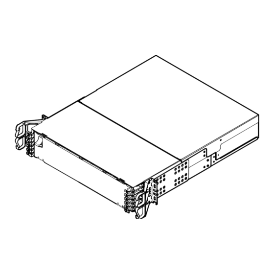
Page 2: General
General Figure 1 — EDGE Housings This document describes installation of the EDGE™ 1U, 1U-SP, 2U, and 4U Housing Solutions (Figure 1). Except where installation of another housing is unique, only the 4U housing is illustrated. Carton Contents • Housing, either 1U, 1U-SP, 2U, or 4U rack-height •... -
Page 3: Installation
Installation Rack or Frame Mounting Step 1: Identify the position on the rack where the housing will be installed and partially install screws to rest the mounting brackets on Figure 2. Step 2: Move brackets forwards or backwards for desired frontal projection and rest the mounting brackets behind the screw heads just installed in the rack. - Page 4 Weather Precautions • Always follow the recommended storage temperature guidelines for the cable when storing a trunk/pigtail. Each cable type will have a storage temperature rating that can be found on the product speci cation sheets. Storage outside of these ranges can cause damage to the cables.
-
Page 5: Trunk Cable Placement With The Pulling Grip
CAUTION: Fiber optic cable is sensitive to excessive pulling, bending, and crushing forces. Consult the cable speci cation sheet for the cable you are installing. Do not bend the cable more sharply than the minimum recommended bend radius. Do not apply more pulling force to the cable than speci ed. Do not crush the cable or allow it to kink. -
Page 6: Pulling Grip Removal
4.2.2 Pulling Grip Removal Step 1: Remove the pull line and clean any dirt or debris from the outer surfaces of the sleeve. IMPORTANT: Disassemble the pulling sleeve on a work surface free from dirt, excessive heat, or any solvents. Step 2: Lift the hook-and-loop aps to expose the zipper pull. -
Page 7: Optional) Install Cdf Bracket
96- and 144- ber Trunks: Step 8: Starting with the mesh bag closest to the furcation body, remove the tape and mesh to expose the rst set of three folded legs (Figure 10). Unfold the legs from around the bend control device. Repeat this step on the middle mesh bag, and then conclude by removing the end mesh bag. -
Page 8: Install Trunk Cables From Either Side Of The Housing
Figure 11 — Install CDF Bracket Install Trunk Cables from Either Side of the Housing If necessary to install trunk cables from the rear of a housing, refer to Section 4.5 for details on reorienting the backplates to accommodate rear cable entry. In a 4U housing trunk cables may be installed into the backplates in the top of the housing in an upside-down orientation, if desired or necessary, to accommodate additional cables. -
Page 9: Installing Trunk Cable With Keyhole Adapter
Step 3: Open rear housing door. Route cables into housing through side openings. Figure 13 — Install Trunk Cables with Keyhole Cradle Step 4: Insert cradle feet into backplate and slide into slots to lock in place. Step 5: Repeat for all trunk cables and allow connectorized MTP legs to ow out the rear of the housing until ready to clean and mate in the appropriate module or panel. -
Page 10: Install Trunk Cables From Rear Of Housing
Install Trunk Cables from Rear of Housing If rear cable entry into the housing is desired or necessary, the backplates must be turned 180 degrees before installing the cables. Step 1: Remove existing backplates by removing the four screws (Figure 15). Step 2: Turn the backplate 90 degrees as shown and reinstall the four screws. -
Page 11: Optional) Remove Housing Trunk Plate
(OPTIONAL) Remove Housing Trunk Plate If cable entry strain-relief is accomplished in a location external to the housing, the trunk plate may be removed to allow more room behind the housing (Figure 16). Step 1: (For 4U housing only) Remove side panel from each side of the housing. Step 2: Remove any screws holding the access panels to the housing. -
Page 12: Install Edge™ Modules
Install EDGE™ Modules 4.7.1 Into EDGE-01U-SP, EDGE-02U and EDGE-04U Housings Step 1: Remove MTP connector and adapter dust caps. Clean connectors and adapters using the MTP ® cleaning tool (P/N 2104466-01). Follow the instructions provided with the tool. Step 2: Mate the MTP connector(s) into the adapter(s) at the back of the module (Figure 17) with the MTP key down/opposite the module label. -
Page 13: Into Edge-01U Housing
4.7.2 Into EDGE-01U Housing CAUTION: When removing the trays, position yourself in the center of the rack and use both hands to pull the tray out. Step 1: Press latches down to open and lower front door. Step 2: Using tabs on the side of the drawer, lift and pull out drawer horizontally until reaching hard stops (Figure 18). -
Page 14: Connect Jumpers To Edge™ Modules
Figure 19 — Install EDGE Module 4.7.3 Connect Jumpers to EDGE™ Modules CAUTION: When removing the trays, position yourself in the center of the rack and use both hands to pull the tray out. Failure to so may damage the tray guides or cause shelf movement past the detents. Step 1: Open housing front door and pull out tray (Figure 20, step 1). -
Page 15: Install Mtp ® Adapter Panels
Install MTP Adapter Panels ® The MTP adapter panel comes in con gurations to support both single-mode (SM) and multimode (MM) applications. Adapters have been clearly labeled identifying port (1, 2, 3, etc.). Each tray within the housing will support a maximum of four MTP panels. Adapter panels may be installed from the front or back of the EDGE™... -
Page 16: Connecting Wiring Harnesses, Mtp Jumper, Mtp Conversion Harnesses, Or
Step 1: With the trunk cables securely installed in the housing, remove the dust caps from the MTP trunk connector legs and MTP adapter panel (only on the rear side of the adapter panel). Keep dust caps in place on the front of the adapter panel, if applicable. Clean connectors using the MTP cleaning tool (P/N 2104466-01). - Page 17 Step 3: Mate the connectors in the adapters (Figure 23). If MTP adapter is equipped with shutter, lower the shutter rst, then mate the connectors. Step 4: Route the connected cable either to the right or to the left of the housing. All cables should route in the same direction.
-
Page 18: Recordkeeping
Recordkeeping Detailed and accurate recordkeeping enables users to logically “map” ber terminations within the Data Center from Local equipment to Remote equipment. It is recommended that users employ labeling guidelines outlined in ANSI/TIA-606-A-1 for mapping the network. Guidelines below provide an analogous solution in accordance with this standard for labeling to be used with the EDGE™... - Page 19 Step 1: Frame/Cabinet Location (Figure 26) Identify location of Frame or Cabinet within the oor space grid coordinate system. Preprint labels and adhere to Front and Back of Frame or Cabinet at the top and bottom. Figure 26 — Frame/Cabinet Label Location Step 2: Housing/Chassis Location (Figure 27) Identify location within the Frame or Cabinet (in rack units from the bottom) by locating the Top/Left...
- Page 20 Step 3: Tray Location (Figure 28)) Identify location of tray within the housing/chassis. Trays come pre-labeled 01 to 12 from the bottom to the top of the chassis. Figure 28 — Tray Label Location Step 4: Module Location with Fiber or Port Range (Figure 29) Each tray comes pre-labeled A through D to identify Module position within the tray.
-
Page 21: Cable/Jumper Labeling
Step 5: Documentation (Figure 30) Identify remote location termination and determine code to be printed. It should only be necessary to print the remote location. Printed code from label makers may be a xed to the label card on the inside of the front door. -
Page 22: Troubleshooting And Maintenance
Troubleshooting and Maintenance Testing Use the Fluke MultiFiber™ Pro Optical Power Meter and Test Kits for testing the MTP connections. Follow the ® Fluke Networks manual which can be found on-line at http://download. ukenetworks.com/Download/Asset/MultiFiberPro_9827313_ENG_A_W.PDF. A sample test procedure can be seen in Figure 31. Figure 31 * —... -
Page 23: Replace Edge™ Module
Replace EDGE™ Module Step 1: Open front door and pull tray out. Step 2: Press latch on LC connector and pull connector out (Figure 32). If jumper is equipped with MTP connector, simply grasp connector body and pull connector out of the adapter. (NOTE: only LC connectors shown in Figure 30.) Step 3: Press lever on right side of module and pull module out. -
Page 24: Remove Trunk Cable
Remove Trunk Cable 6.3.1 Cable in Keyhole Cradle If necessary to replace trunk cable or keyhole cradle, remove per the directions in this section (Figure 33). Install new cable or cradle per the directions in Section 4.4. Step 1: Pull back on both latches while pushing cradle in opposite direction. Lift cradle and cable up. Step 2: Open cradle door. -
Page 25: Changing The Polarity Of An Lc Uniboot Connector
A complete listing of the trademarks of Corning Optical Communications is available at www.corning.com/opcomm/trademarks. All other trademarks are the properties of their respective owners. Corning Optical Communications is ISO 9001 certi ed. © 2009, 2019 Corning Optical Communications. All rights reserved.
Need help?
Do you have a question about the EDGE-02U and is the answer not in the manual?
Questions and answers