
Related Manuals for B+K precision Sefram DAS1800


Summary of Contents for B+K precision Sefram DAS1800
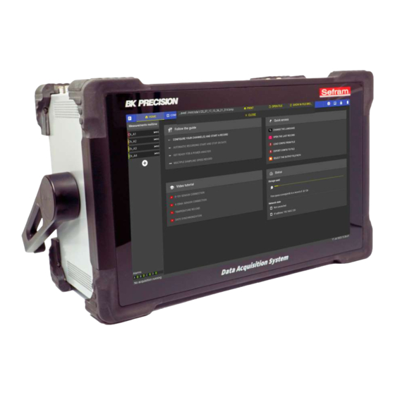
- Page 1 User manual DAS1800 High Speed Modular Data Acquisition Recorder bkprecision.com - sefram.com...
-
Page 2: Safety And Symbols
Sefram CHAPTER 1. SAFETY AND SYMBOLS Chapter 1 Safety and symbols To ensure proper use of the unit, please observe the safety and operating requirements described in this manual. Specific warning signals appear throughout this manual to draw your attention to important points. Please read the following instructions in this chapter carefully before using your Data Acquisition System. -
Page 3: Category Rating
Sefram CHAPTER 1. SAFETY AND SYMBOLS Before powering up the device : • Read and understand the safety and operating information in this manual. • Follow all listed safety precautions. • Operating the instrument with the wrong supply voltage voids the warranty •... -
Page 4: Ground The Instrument
Sefram CHAPTER 1. SAFETY AND SYMBOLS 1.0.3 Ground the instrument To minimize the risk of electric shock, the chassis of the instrument must be connected to a safety ground. The instrument is earthed via the earth conductor of the supplied power cable, which must be plugged into an approved three-conductor electrical socket. - Page 5 Sefram CHAPTER 1. SAFETY AND SYMBOLS Measurements taken with this instrument may be out of specification if the instrument is used in environments that may include rapid changes in temperature or humidity, sunlight, mechanical vibration and/or shock, acoustic noise, electrical noise, strong electric fields or strong magnetic fields. •...
-
Page 6: Particular Precautions
Sefram CHAPTER 1. SAFETY AND SYMBOLS 1.0.8 Particular precautions • Do not use this product for purposes other than those for which it is intended. • To avoid electric shock, observe the following precautions when working with dangerous volt- ages: •... -
Page 7: Concerning The Exported Devices In North America
Sefram CHAPTER 1. SAFETY AND SYMBOLS 1.0.9 Concerning the exported devices in North America This equipment has been tested and found to comply with the limits for a Class A digital device, pursuant to part 15 of the FCC Rules. These limits are designed to provide reasonable protection against harmful interference when the equipment is operated in a commercial environment. -
Page 8: Table Of Contents
Sefram CONTENTS Contents 1 Safety and symbols 1.0.1 Category rating ..........1.0.2 Power supply . - Page 9 Sefram CONTENTS 3.7.2 Start at date : ..........30 3.7.3 Trigger on level : .
- Page 10 Sefram CONTENTS 9 Metrology 9.1 Calibration ..........67 10 Servicing 10.1 For users not based in America .
- Page 11 Sefram LIST OF FIGURES List of Figures 2.1 General views ..........14 2.2 Supplied accessories .
- Page 12 Sefram LIST OF FIGURES 7.1 Access to system settings ......... . 57 7.2 Network configuration page .
- Page 13 Sefram LIST OF TABLES List of Tables 1.1 Symbols on the device ..........1.2 Symbols in the manual .
-
Page 14: Introducing The Device
Sefram CHAPITRE 2. INTRODUCING THE DEVICE Chapitre 2 Introducing the device Introduction SEFRAM thanks you for your confidence in us and is pleased to present the DAS1800. This new-generation multi- channel Data Acquisition System is developed and manufactured in France. Its ability to record and analyze all types of electrical signals (sensors, electrical relays, electrical networks, etc.) makes it ideal for a wide range of industrial applications (maintenance, R&D, production, etc.). -
Page 15: Supplied Accessories
Sefram CHAPITRE 2. INTRODUCING THE DEVICE 2.2.1 Supplied accessories The device is provided with : Main power cord (IEC) Carrying case Sub-D15 HD connector (x1) Sub-D25 connector (x1) 8-pin connector for external power supply output 4-pin connector (x8) (with multiplexed board) Pair of male banana plug connectors (x4) (for universal and high-voltage acquisition boards) 2.2 : Supplied accessories... -
Page 16: Interfaces
Sefram CHAPITRE 2. INTRODUCING THE DEVICE Universal module Multiplexed module High voltage module High impedance module 2.3 : Acquisition modules IGURE Specifications Universal board Multiplexed board High voltage board High impedance board Number of channels 4 isolated single-pole channels 8 non-isolated differential channels 4 isolated differential channels 4 isolated single-pole channels Maximum voltage... -
Page 17: View From Above
Sefram CHAPITRE 2. INTRODUCING THE DEVICE 2.4 : View from above IGURE Symbol Description On/off push-button Ethernet port for connecting the device to a computer network (x2) (see remote control section) HDMI port for transferring the screen display to an external display USB port for connecting mouse, keyboard, USB sticks or Wi-Fi (option) (x4) Acquisition boards 2.5 : Interfaces vue arrière... -
Page 18: Optional Accessories
Sefram CHAPITRE 2. INTRODUCING THE DEVICE 2.2.4 Optional accessories Optional accessories are listed below : • Logic channel box : allows logic inputs/outputs to be transferred to an external module, increasing the maxi- mum permissible voltage. • Logic channel cable : allows inputs/outputs to be remotely connected to a standard banana plug cable •... -
Page 19: Interface Layout
Sefram CHAPITRE 2. INTRODUCING THE DEVICE Interface layout 2.4.1 Navigation Navigation on the device is via the menu bars at the top of the page (main and secondary). 2.4.2 Status The bar at the bottom indicates the device status: • Registration status •... -
Page 20: Getting Started
Sefram CHAPITRE 3. GETTING STARTED Chapitre 3 Getting started Installing and removing acquisition modules Module installation and removal must be carried out with the power off. When doing so, switch off the device and ensure that no cables are connected to the module inputs. Add an acquisition module : The module plugs into the device as a simple way. -
Page 21: Working Directory
Sefram CHAPITRE 3. GETTING STARTED Figure 3.2: File Manager "sda1" (solid drive a1) (1) corresponds to the contents of the device’s disk memory. It is also available by pressing "DISK" (4). If a USB stick is connected to the device, then a "sdb1" folder will be displayed, and will be available from this page. -
Page 22: Channels And Measurements
Sefram CHAPITRE 3. GETTING STARTED Figure 3.3: File creation By default, screenshots (1) and measurement recordings (2) are at the root of the disk. Click on create a new folder, name and select it then click on "choose as working directory". Figure 3.4: File creation as working directory Channels and measurements A channel corresponds to a physical input to the device. -
Page 23: Analog Channel Settings
Sefram CHAPITRE 3. GETTING STARTED A measurement is a direct input or calculation derived from a physical channel. The type of measurement available depends on the property being measured and configuration of the physical channel. Examples include RMS, average, minimum, maximum, derivative and integral. Analog channel settings To access acquisition board analog channel settings, use the main navigation bar by tapping on Configuration then Channels. -
Page 24: Page Configuration
Sefram CHAPITRE 3. GETTING STARTED The Min and Max columns define the range measured by the channel. It has an impact on measurement accuracy (see accuracy section for more details). The button automatically centers zero between Min and Max terminals (editable). The Measurement column defines which measurements associated with the channel will be activated for vie- wing and/or recording. -
Page 25: Digital Channels Setting
Sefram CHAPITRE 3. GETTING STARTED a digital filter (software processing). Alternatively, apply a hardware filter (signal input processing) from a choice of 100Hz, 1000Hz or 10,000Hz. By pressing the icon shown below, you can duplicate all the parameters of the selected channel to other channels on the device. -
Page 26: Logic Inputs (Vlog)
Sefram CHAPITRE 3. GETTING STARTED 3.5.1 16 logic inputs (Vlog) To open all the parameters of a digital input, press the symbol from the measure colomn : The logic inputs can monitor all signals up to 24V. To increase the maximum permissible voltage, the Logic channel box option 917008000 is available. -
Page 27: Alarm Outputs
Sefram CHAPITRE 3. GETTING STARTED There are also 3 others power supply outputs (3.3V, 5V, 12V, 24V) on the rear pannel (5W maximum) : 3.5.3 Alarm outputs To set the parameters for the 4 alarm outputs, please refer to the section on alarms setting. Recording measurements 3.6.1 Recording file configuration Recording file configuration is available from the menu Configuration >... -
Page 28: Sampling Frequency
Sefram CHAPITRE 3. GETTING STARTED Recording file size or duration limit In addition to triggers, it is also possible to add a limit to the recording file. This can be used, for example, to avoid obtaining a very large file if the event associated with the end-of-recording trigger is never reached. If the "Enable record file size limit"... -
Page 29: Setting Recording Frequencies
Sefram CHAPITRE 3. GETTING STARTED 3.11 : Setting recording frequencies IGURE You can customize the information displayed using the displayed columns field (1), and filter the channel display using the Filter by name field (2). 4 different sampling frequencies can be set (3). The same measurement can be recorded at a single frequency. -
Page 30: Start And Stop Settings
Sefram CHAPITRE 3. GETTING STARTED Start and stop settings To set your acquisition trigger conditions, go to Configuration > Records > Trigger. 3.12 : Start and stop settings IGURE Each record must be set up with a start condition and a stop condition (1). For each, there are 3 different types of triggers : manual, date and trigger (2). -
Page 31: Trigger On Level
Sefram CHAPITRE 3. GETTING STARTED 3.14 : Trigger on level IGURE First define the physical channel and its associated measurement to which you want to apply the trigger condi- tion (1). Then describe the condition by selecting "level" in type, the ">" or "<" operation for the overshoot direction, and the threshold value (2). -
Page 32: Trigger On Slope (Available In A Later Version)
Sefram CHAPITRE 3. GETTING STARTED 3.7.4 Trigger on slope (available in a later version) 3.15 : Trigger on slope IGURE To set up a slope trigger, also define the physical channel and associated measurement to which you wish to apply the recording condition (1). Choose slope (2) . The "+" or "-" sign in front of the amplitude value defines the direction of the slope (3). -
Page 33: Pre-Trigger
Sefram CHAPITRE 3. GETTING STARTED 3.16 : Combination of conditions IGURE In the example above, if one of the defined conditions is true, then recording is triggered (1). If the voltage of analog channel 1 is less than 50V OR if the RMS value of channel 2 is greater than 25V for 100 ms, then recording is triggered (2). -
Page 34: Post-Trigger
Sefram CHAPITRE 3. GETTING STARTED 3.18 : Inhibit function IGURE 3.7.7 Post-trigger The user can set a time during which the device continues to record after the stop condition has been triggered. 3.19 : Post-trigger IGURE 3.7.8 Setting save You can save a acquisition configuration file (1) with all the parameters defined for an acquisition, it can be recalled later by importing it (3): •... -
Page 35: Creation Of Configuration File
Sefram CHAPITRE 3. GETTING STARTED • Settings for real-time pages You can also save a system configuration file (2) that includes all system parameters, it can be recalled later by importing it (3): • Network • Time synchronization • Screen •... -
Page 36: Measurement Data Display
Sefram CHAPITRE 4. MEASUREMENT DATA DISPLAY Chapitre 4 Measurement data display Real-time display To view your measurements in real time, click on the "real time" tab in the main navigation bar : 4.1 : Real-time data display IGURE To view previously configured measurements, drag and drop them into the graph area (1). You can also add or remove a measurement from the graph area by pressing and holding. -
Page 37: Dmm Display
Sefram CHAPITRE 4. MEASUREMENT DATA DISPLAY 4.1.2 DMM display DMM mode displays real-time measurements in digital format. In order to be visible, the value displayed is an average. You can use the HDMI output on the unit to transfer the image to a display. 4.2 : DMM Display IGURE To display measurements in numerical format, simply press and drag the measurement over the graphic area. -
Page 38: Dashboard Personalization
Sefram CHAPITRE 4. MEASUREMENT DATA DISPLAY The DMM average period can be set on 200ms or 2s. The number of samples used for the calcula- tion depends on the acquisition module speed frequency. For instance, with an universal acquisition module, it will be 1 MSa/s. Custom display These two dashboards (custom 1 and custom 2) are fully configurable. -
Page 39: Visualization And Graphical Analysis
Sefram CHAPITRE 4. MEASUREMENT DATA DISPLAY To redesign widgets you can : In touch navigation : in edit mode, pinch to change size and drag to move. Mouse navigation : in edit mode, use the scroll wheel to change size and drag to move. Go to ’Size and position’... -
Page 40: Zooming In And Out On X And Y Axes
Sefram CHAPITRE 4. MEASUREMENT DATA DISPLAY 4.6 : Zooming in and out on X and Y axes IGURE By moving the thumb and forefinger closer or further apart on the Y ordinate axis (amplitude), it’s possible to zoom in and out between the defined limits (1). The same applies to the X-axis, to change the time base (2). On a computer or if a mouse is connected to the device, use the mouse wheel to perform this function, positioning the cursor on the desired axis. -
Page 41: Recording Analysis
Sefram CHAPITRE 4. MEASUREMENT DATA DISPLAY 4.7 : Graphic display parameters IGURE On the vertical bar to the right of the screen, a set of parameters is available (1). Use the arrow at the bottom right of the screen to open the text description of each parameter (2). Symbol Description Selects the measurements to be displayed in the graphics area... -
Page 42: File Transfer
Sefram CHAPITRE 4. MEASUREMENT DATA DISPLAY 4.8 : Recording measurement file IGURE By pressing data (1), you can : • Access all saved measurement files • Convert the displayed measurement file to .csv format, which will be found in the file manager. File transfer 4.4.1 File retrieval via USB key Plug a USB key into one of the device’s ports. - Page 43 Sefram CHAPITRE 4. MEASUREMENT DATA DISPLAY Then go to Configuration > Remote > FTP Activate the FTP protocol, setting a password if necessary. By default, the connection is in anonymous mode on port 20 + 21. User manual...
-
Page 44: Advanced Features
Sefram CHAPITRE 5. ADVANCED FEATURES Chapitre 5 Advanced features Sensors library Each measurement is associated with a sensor. To access the sensor library, go to Configuration > Channel > Sensors library A table listing all sensors and their parameters is shown on this page. 5.1 : Sensors library table IGURE You can search for sensors already in the library by name (1) or filter the information given by column for each... -
Page 45: Ma Sensor Settings
Sefram CHAPITRE 5. ADVANCED FEATURES 5.2 : 4-20 mA sensor settings IGURE Set sensor type to "Other" (1) and sensor interface to 4-20mA_with_Shunt (2). Enter the unit of the sensor’s physical input (3). Enter the associated information in the various fields (4). If the unit is not available in the drop-down list, you can add it manually. -
Page 46: Alarms Setting (Available In A Later Version)
Sefram CHAPITRE 5. ADVANCED FEATURES 5.4 : Affine conversion settings IGURE In the case of our sensor, when it measures 0 Bar, it delivers 4mA, which corresponds to 0.2V across shunt (1). When it measures 10 Bar, the sensor delivers 20 mA, which corresponds to 1V across shunt (2). Alarms setting (available in a later version) 5.2.1 4 logic output (Alarms) Alarms A, B, C and D send a TTL voltage signal when the set event occurs. -
Page 47: Web Server
Sefram CHAPITRE 5. ADVANCED FEATURES 5.3.1 Web server The system incorporates a web server function, enabling a connection to be established via the Internet from a web browser. To do this, enter the IP address in the browser address bar (1). You’ll find the device’s IP address in the "Status"... -
Page 48: New Vnc Viewer® Connection
Sefram CHAPITRE 5. ADVANCED FEATURES 5.7 : New VNC viewer® connection IGURE The new connection appears in the list, click to connect : You can secure your connection with a password. 5.8 : Connection IGURE You can then operate the device with full access to all functions : User manual... -
Page 49: Scpi Protocol
Sefram CHAPITRE 5. ADVANCED FEATURES 5.9 : VNC viewer® control IGURE SCPI protocol SCPI (Standard Commands for Programmable Instruments) is a universal programming language for electronic test and measurement instruments, based on the IEEE 488.1 and IEEE 488.2 standards. Commands are ASCII textual strings which are sent to the instrument over the physical layer. -
Page 50: Arguments
Sefram CHAPITRE 5. ADVANCED FEATURES Abbreviating commands The command syntax shows some characters in a mixture of upper and lower case. Abbreviating the command to only sending the upper case has the same meaning as sending the upper and lower case command. For example, the command “DATe”... -
Page 51: Programming Dictionary
Programming dictionary 5.8.1 Requests list HEADER DESCRIPTION RESPONSE EXEMPLE *IDN? Identification request SEFRAM, SEFRAM 8460 Version 4.7.2 Product Name, (N:00010) Serial Numer, VersionMajor.VersionMinor *OPT? Idendtification of options Number of acquition boardsSS titi :DATe? Return the current date Day,Month,Year 30,12,2022 :HOUrs? Return the current time Hour,Minutes,Seconds 09,53,37... -
Page 52: Command List
5.8.2 Command list HEADER DESCRIPTION PARAMETERS EXEMPLE *REM Start remote control *REM *LOC Stop remote control *LOC :MEMSpeed Set recording frequency Frequency (Hz) :MEMSpeed 10000 :START:MANual Start recording :START:MANual :STOP:MANual Stop recording :STOP:MANual :SCREEN Change current screen REplay, SETUP, SCOpe :SCREEN SCO :FILE:NAMe Set record file name... -
Page 53: Examples
Sefram CHAPITRE 5. ADVANCED FEATURES Examples Bellow an example of a Python implementation Listing 5.1: SCPI python implemntation exemple i m p o r t t i m e i m p o r t t e l n e t l i b TIMEOUT = 0 . -
Page 54: Scpi User Interface
Sefram CHAPITRE 5. ADVANCED FEATURES Figure 5.10: SCPI user interface User manual... -
Page 55: Mdf4 File Format
Sefram CHAPTER 6. MDF4 FILE FORMAT Chapter 6 MDF4 file format Measurement Data Format version 4 (MDF4) is an ASAM file standard for storing measurement data in a binary file format. For more information about the MDF4 file format, please visit https://www.asam.net/standards/detail/mdf/wiki/. Format The MDF contains both raw measurement data and the metadata needed to interpret the raw data. -
Page 56: Example
Sefram CHAPTER 6. MDF4 FILE FORMAT Example Here’s an example of a Python implementation using the Asammdf library to open an MDF4 record Listing 6.1: Exemple d’utilisation de la bibliothèque MDF4 en Python from asammdf i m p o r t mdf = MDF( ’... -
Page 57: System
Sefram CHAPITRE 7. SYSTEM Chapitre 7 System Ergonomic settings To set the general system settings, go to Configuration > System 7.1 : Access to system settings IGURE You’ll then be able to adjust : • Screen : brightness, screen saver •... -
Page 58: Time Zone
Sefram CHAPITRE 7. SYSTEM To set up a local NTP server, contact your IT department, who will be able to help you. 7.3.3 Time zone This parameter lets you define the time zone to which the device refers. Network settings 7.4.1 Ethernet To connect your device to a network, go to Configuration >... -
Page 59: Enp2S0 Interface
Sefram CHAPITRE 7. SYSTEM To configure the network, click on "Configure" (2), and the following page will appear : 7.3 : Enp2s0 Interface IGURE If your network is directly connected to a DHCP server via a router, you need to check DHCP mode (1). Your network will automatically assign an available network address to your device, thus avoiding address conflicts. -
Page 60: Fixed Ip Address Setting
Sefram CHAPITRE 7. SYSTEM 7.4 : Fixed IP address setting IGURE The device is connected to the PC via ethernet cable, and the configurations are as follows : 7.5 : Manual IP configuration of PC and the recorder IGURE User manual... -
Page 61: User Level
Sefram CHAPITRE 7. SYSTEM The configuration shown below is an example. If you have any doubts about your settings, please contact your IT department. In a point-to-point connection, you can send SCPI commands using the supplied programming manual. This means you can edit and run your own script over an isolated connection. User level Several user levels can be defined, giving access to more or less advanced functions and information. -
Page 62: Bug Report
Sefram CHAPITRE 7. SYSTEM Expert level: Certain functions or additional information become available. Admin level: This level is dedicated to your company’s IT department or competent person. It gives access to network security parameters. Bug report If you notice a malfunction while using the device, a dedicated bug report menu is available: Configuration > System >... -
Page 63: Technical Specifications
Sefram CHAPTER 8. TECHNICAL SPECIFICATIONS Chapter 8 Technical specifications User manual... - Page 64 High Speed Modular Data Acquisition System DAS1800 Specifications, base unit Note: All specifications apply to the unit after a temperature stabilization time of 30 minutes over an ambient temperature range of 23 °C ± 5 °C. Data Acquisition System Power Supply Rail Recording (files written to SSD) Maximum Power Consumption Max Sampling Rate...
- Page 65 High Speed Modular Data Acquisition System DAS1800 Specifications, measurement Modules Note: All specifications apply to the unit after a temperature stabilization time of 30 minutes over an ambient temperature range of 23 °C ± 5 °C. Universal Module (D18-UNI4) Time and Counting Number of Channels Threshold Set by user, auto...
- Page 66 High Speed Modular Data Acquisition System DAS1800 Specifications, measurement Modules Note: All specifications apply to the unit after a temperature stabilization time of 30 minutes over an ambient temperature range of 23 °C ± 5 °C. Multiplexed Module (D18-MUX8) Temperature ( Thermocouple) Compute Frequency 4 ms Number of Channels...
-
Page 67: Metrology
Sefram CHAPTER 9. METROLOGY Chapter 9 Metrology Calibration You are in possession of a measuring instrument for which the metrological conditions of measurement are de- fined in the specifications of this manual. Climatic and environmental conditions limit the specifications of your instrument. -
Page 68: Servicing
Sefram CHAPTER 10. SERVICING Chapter 10 Servicing 10.1 For users not based in America 10.1.1 Warranty Your instrument is guaranteed for three years (36 months) parts and labor against any manufacturing defect or operating hazard. This warranty begins on the date of delivery and ends 1095 calendar days later. If the device is covered by a warranty contract, the latter supersedes or replaces the warranty conditions listed above. -
Page 69: After-Sales Contact
Sefram CHAPTER 10. SERVICING The warranty period for after-sales service outside the appliance warranty period is 3 months. All spare parts become the property of the user, and replaced parts become the property of SEFRAM. In the event of insurance coverage, the product becomes the property of the insurance company at its exclusive request. -
Page 70: For Users Based In America
Sefram CHAPTER 10. SERVICING Figure 10.1: Display areas Acceptance criteria: • Zone A (central zone): fewer than 5 defective pixels in total and fewer than 3 contiguous pixels. • Zone B (total screen area): less than 9 defective pixels over the entire screen area, with Zone A conditions met. -
Page 71: Packaging
Sefram CHAPTER 10. SERVICING B&K Precision Corp. : 22820 Savi Ranch Parkway Yorba Linda,CA 92887 bkprecision.com 714-921-9095 The device must be accompanied by a detailed description of the fault, and must be returned with all standard accessories (cords, plugs, etc.). Consumables (batteries, etc.) and optional accessories (case, bag, etc.) are guaranteed for 3 months against manufacturing defects. -
Page 72: Display Areas
Sefram CHAPTER 10. SERVICING surface. SEFRAM’s quality department has made installation of your instrument’s display conditional on compli- ance with the manufacturers’ acceptance conditions. Figure 10.2: Display areas Acceptance criteria: • Zone A (central zone): fewer than 5 defective pixels in total and fewer than 3 contiguous pixels. •... -
Page 73: Annexes
Sefram CHAPITRE 11. ANNEXES Chapitre 11 Annexes 11.1 Revisions Version and date Firmware version associated Modified chapters Modification type 1.0 / October 2023 1.0.x Document creation User manual...
Need help?
Do you have a question about the Sefram DAS1800 and is the answer not in the manual?
Questions and answers