Advertisement
Quick Links
Model W200B03/002C20
Impact ICP® quartz force sensor, 500 lb comp., 10 mV/lb
Installation and Operating Manual
For assistance with the operation of this product,
contact PCB Piezotronics, Inc.
Toll-free: 800-828-8840
24-hour SensorLine: 716-684-0001
Fax: 716-684-0987
E-mail: info@pcb.com
Web: www.pcb.com
Advertisement

Related Manuals for PCB Piezotronics W200B03/002C20


Summary of Contents for PCB Piezotronics W200B03/002C20
- Page 1 Model W200B03/002C20 Impact ICP® quartz force sensor, 500 lb comp., 10 mV/lb Installation and Operating Manual For assistance with the operation of this product, contact PCB Piezotronics, Inc. Toll-free: 800-828-8840 24-hour SensorLine: 716-684-0001 Fax: 716-684-0987 E-mail: info@pcb.com Web: www.pcb.com...
- Page 2 Piezotronics, user servicing or repair is critical test. not recommended and, if attempted, may void the factory warranty. Routine PCB Piezotronics maintains an ISO- maintenance, such as the cleaning of 9001 certified metrology laboratory and electrical connectors, housings, and offers calibration services, which are...
- Page 3 50% of the general contact numbers are: replacement cost returned item(s). PCB will provide a price PCB Piezotronics, Inc. quotation replacement 3425 Walden Ave. recommendation for any item whose Depew, NY14043 USA repair costs would exceed 50% of...
-
Page 4: China Rohs Compliance
PCB工业监视和测量设备 - 中国RoHS2公布表 PCB Industrial Monitoring and Measuring Equipment - China RoHS 2 Disclosure Table 有害物质 汞 镉 六价铬 (Cr(VI)) 多溴联苯 (PBB) 多溴二苯醚 (PBDE) 部件名称 铅 (Pb) (Hg) (Cd) 住房 PCB板 电气连接器 压电晶体 环氧 铁氟龙 电子 厚膜基板 电线 电缆 塑料 焊接... - Page 5 Component Name Hazardous Substances Lead Mercury Cadmium Chromium VI Polybrominated Polybrominated (Pb) (Hg) (Cd) Compounds Biphenyls Diphenyl (Cr(VI)) (PBB) Ethers (PBDE) Housing PCB Board Electrical Connectors Piezoelectric Crystals Epoxy Teflon Electronics Thick Film Substrate Wires Cables Plastic Solder Copper Alloy/Brass This table is prepared in accordance with the provisions of SJ/T 11364.
- Page 6 FORCE SENSOR OPERATION MANUAL 1.0 INTRODUCTION sensor cost-per-channel is substantially lower, since they operate through standard, low-cost coaxial cable, and do not require expensive charge amplifiers. ICP force sensors incorporate a built-in MOSFET microelectronic amplifier. This serves to convert the high Refer to the installation/outline drawing and specification impedance charge output into a low impedance voltage signal sheet at the back of this manual for details and dimensions of...
- Page 7 FORCE SENSOR OPERATION MANUAL Figure 3 - Series 200 ICP Impact Sensor Polyimide film tape covers the cap surface to reduce high frequency ringing associated with metal-to-metal impacts. Internal mounting holes with uniform 10-32 threads are prepared on each end of the sensor in the smaller models. Two Model 081B05-mounting studs (M081B05 for metric Figure 4 - Series 201 to 207 ICP Ring Force Sensor...
- Page 8 FORCE SENSOR OPERATION MANUAL Figure 6 outlines some possible mounting configurations of the link series of sensors. ® Figure 6 – Series 221 to 227 ICP Force Link Sensor Mounting Method 3- COMPONENT TRIAX SENSORS PCB’s line of 3-Component force sensors is capable of simultaneously measuring force in three (3) orthogonal directions (X, Y, and Z).
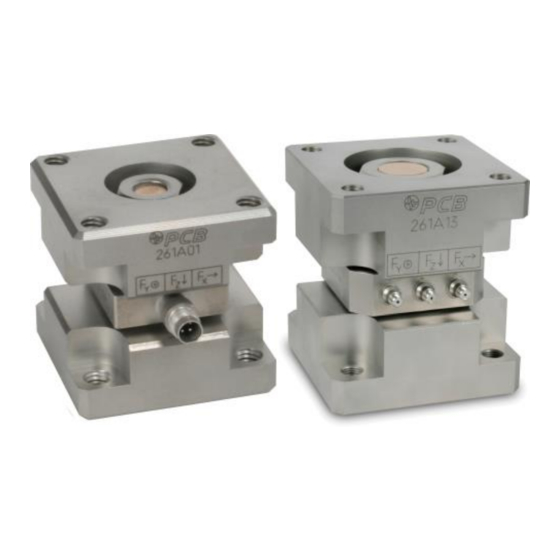
- Page 9 FORCE SENSOR OPERATION MANUAL repair document for proper instructions for returning the sensor to PCB for recalibration. Figure 8 – SERIES 3-COMPONENT TRIAX FORCE SENSORS ® version Charge mode version PENETRATION Penetration style sensors are similar to the axial models but are specifically designed for compression and impact force measurements in materials testing applications.
-
Page 10: Installation
FORCE SENSOR OPERATION MANUAL on both ends of the sensor. Link, integrated link, and It is important that the surface to which each sensor is mounted freestanding installations are possible as outlined in Figure 9. be perfectly flat to avoid flexing of the base, which could affect sensor sensitivity and result in erroneous data (see Caution –... - Page 11 FORCE SENSOR OPERATION MANUAL The stud or bolt holds the structure together and applies preload to the force ring as shown in Figure 13. In the typical link installation, shown on the left in Figure 13, part of the force between the two structures is shunted through the mounting stud.
- Page 12 FORCE SENSOR OPERATION MANUAL Non-Typical Installation Used for Force Limited Typical Link Installation Vibration Testing When installing ICP ring and 3-component type sensors, a PCB signal conditioner with at least one channel of DC coupling capability is recommended to properly monitor sensor output voltage as it corresponds to the desired preload.
- Page 13 FORCE SENSOR OPERATION MANUAL ICP® models this may be an electrical limitation (applying an See Guide G-0001B for powering and signal conditioning excessive load under sudden dynamic condition outside the information pertaining to all ICP instrumentation. specified range may damage the internal electronic circuitry). Most of the line powered signal conditioners manufactured by With most sensors, the specified dynamic working range and PCB have an adjustable current feature allowing a choice of...
- Page 14 FORCE SENSOR OPERATION MANUAL 7.0 LOW-FREQUENCY MONITORING The discharge time constant represents the decay rate of an input signal. One DTC represents the amount of time taken for Force sensors used for applications in short term, steady state the signal to decay to 37% of the initial peak value. As monitoring, such as sensor calibration, or short term, quasi- illustrated in Figure 16, this is an exponential decay.
-
Page 15: Troubleshooting
This is the expected range and indicates proper operation. ICP is a registered trademark of PCB Piezotronics MANUAL NUMBER: 18218 MANUAL REVISION: ECN NUMBER:...
Need help?
Do you have a question about the W200B03/002C20 and is the answer not in the manual?
Questions and answers