Table of Contents
Advertisement
Quick Links
Advertisement
Table of Contents

Subscribe to Our Youtube Channel
Related Manuals for Pfeiffer Vacuum MPT 100


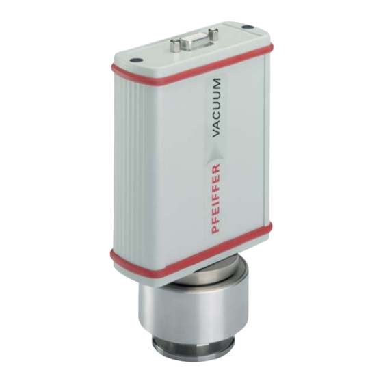
Summary of Contents for Pfeiffer Vacuum MPT 100
- Page 1 MPT 100 Pirani/Cold Cathode Transmitter Operating Instructions...
-
Page 2: Table Of Contents
6.5 Configuring the data exchange ....... . . 13 6.6 Pfeiffer Vacuum Protocol for "RS-485" ......15 6.7 Adjusting the transmitter . -
Page 3: About This Manual
Up-to-date operating instructions can also be downloaded from www.pfeiffer-vacu- um.com. 1.2 Conventions The safety instructions in Pfeiffer Vacuum operating manuals are the result of risk eval- Safety instructions uations and hazard analyses and are oriented on international certification standards as specified by UL, CSA, ANSI Z-535, SEMI S1, ISO 3864 and DIN 4844. -
Page 4: Safety
The operator is obligated to make operating personnel aware of dangers originating from the unit or the entire system. The transmitter MPT 100 has been tested and accepted in compliance with EN 61010/ VDE 0411 “Safety Equipment for Electrical Components”. -
Page 5: Product Description
(see Accessories). The transmitter responds to measurement value queries, type queries and setting com- mands. 3.3 Range of application The unit MPT 100 must be installed and operated in the following ambient conditions: Installation location weather protected (indoor) Protection class... -
Page 6: Transport And Storage
Transport and storage 4 Transport and storage Units without external protection must not come into contact with electrostatically charge- able materials and must not be moved within electrical or magnetic fields. In rooms with moist or aggressive atmospheres, the unit must be airproof shrink- wrapped in a plastic bag together with a bag of desiccant. -
Page 7: Installation
Installation 5 Installation 5.1 Vacuum connection CAUTION Vacuum component! Dirt and damage impair the function of the vacuum component. When handling vacuum components, ensure that they are kept clean and are protect- ed against damage. Ensure that the connection flange is clean, dry and free of grease. CAUTION Excess pressure in the vacuum system 1.5 to 4 bar Damage to health through emission of process media, because elastomer washers... - Page 8 Installation Setting the address selection switch ------------------ ------------------ ------------------ ------------------ Fig. 2: Setting the address selection switch Remove the rubber plugs (not shown in the illustration) from the address selector switch, and set the required address according to the relevant connection situation. ...
- Page 9 Installation Set the address selector switch on the transmitter to RS-232 mode (basic factory-set- Connecting the trans- ting). mitter to the DPS 101 Connect the transmitter to the power supply unit and to the RS-232 interface on the power supply PC using the connection cable.
-
Page 10: Removal Of Components For Their Maintenance
Installation Connecting the trans- mitter to the level TIC 002 converter TIC 002 Transmitter 24 V DC Fig. 6: Connections diagram transmitter - TIC 002 Set address selector switch S on the transmitter to RS-485 mode with the relevant ad- dress. -
Page 11: Operation
When the power supply is switched on, the "sensor" variable is set to "On", (default set- ting), i.e. the MPT 100 is operating in normal mode. Status changes of this variable dur- ing operation are stored only temporarily. The status of the "sensor" variable can be al-... -
Page 12: Selecting Switching Range
Switch off CC sensor by sending ([P:041] with value <<0>>). 6.4 Selecting switching range Depending on the application, the MPT 100 transmitter enables the adjustment of the switching range between Pirani and cold cathode (CC) sensors to avoid – the measuring value being used for control in the transition range or, –... -
Page 13: Configuring The Data Exchange
Operation 6.5 Configuring the data exchange Communication is carried out, depending on the address selector switch setting, via the serial RS-232 interface using the relevant display units or via RS-485 using the Pfeiffer Vacuum protocol: ● 9600 baud ● 8 data bits ●... - Page 14 Parameter 349 contains a logogram for the component name in accordance with the fol- Reading component lowing table: names [P:349] Value Transmitter "..A1" CPT 100 "..A2" RPT 100 "..A3" PPT 100 "..A4" HPT 100 "..A5" MPT 100 "..": means 4 blanks...
-
Page 15: Pfeiffer Vacuum Protocol For "Rs-485
Operation 6.6 Pfeiffer Vacuum Protocol for "RS-485" The telegram frame of the Pfeiffer Vacuum protocol contains only ASCII code characters Telegram frame [32; 127], the exception being the end character of the message . Basically, a master (e.g. a PC) sends a telegram, which is answered by a slave (e.g. electronic drive unit or transmitter). -
Page 16: Adjusting The Transmitter
Operation Activate/send parameter for low pressure (control command) Low pressure adjustment (Parameter [P:741/740], Slave device address: "001") ? ASCII ASCII Applied data types Data type Description Size l1 - l0 Example False / true 000000 / 111111 Positive integer number 000000 to 999999 Positive fixed comma number 001571 equal to 15.71... -
Page 17: Malfunctions
Malfunctions 7 Malfunctions DANGER Strong magnetic field in the vicinity of the sensor head! Danger of death for persons with cardiac pacemakers when the magnetic unit is disas- sembled. Maintenance personnel with active body aids (e.g. cardiac pacemakers) should maintain a safe distance of at least 10 cm from the magnetic unit of the transmitter. -
Page 18: Maintenance And Service
Sending of units Download the forms "Service Request" and "Declaration on Contamination". Fill out the "Service Request" form and send it by fax or e-mail to your Pfeiffer Vacuum service address. Include the confirmation on the service request from Pfeiffer Vacuum with your ship- ment. -
Page 19: Accessories
Accessories 9 Accessories Designation MPT 100 DPS 101, for 1 transmitter, UK plug PT G20 012 DPS 101, for 1 transmitter, US plug PT G20 011 DPS 101, for 1 transmitter, EU plug PT G20 010 DPS 109, for 9 transmitters... -
Page 20: Technical Data And Dimensions
Technical data and dimensions 10 Technical data and dimensions 10.1 Technical data Parameter MPT 100 MPT 100 MPT 100 Anode Flange (in) DN 25 ISO-KF DN 40 CF-R DN 40 CF-R Protection category IP 40 IP 40 IP 40 Seal... -
Page 21: Dimensions
Technical data and dimensions 10.2 Dimensions Berliner Strasse 43 144 ( 159) -
Page 22: Gas Correction Factor
Technical data and dimensions 10.3 Gas correction factor 1E-1 1E-2 1E-3 1E-4 1E-4 1E-3 1E-2 1E-1 real pressure (mbar) Fig. 10: Measurement curve MPT 100 (Pirani) Pirani correction factor: Cold cathode correction factor: 1.00 5.93 1.00 2.39 0.58 0,80 1.02 0.74 1.59... -
Page 23: Declaration Of Conformity
We hereby certify, that the product specified below is in accordance with the provision of EU Electromagnetic Compatibility Directive 2004/108/EEC and EU Low Voltage Di- rective 2006/95/EEC. DigiLine MPT 100 Guidelines, harmonised standards and national standards and specifications which have been applied: DIN EN 61010-1: 2002... - Page 24 Pfeiffer Vacuum stands for innovative and custom Leading. Dependable. Customer Friendly vacuum solutions worldwide. For German engineering art, competent advice and reliable services. Ever since the invention of the turbopump, we´ve been setting standards in our industry. And this claim to leadership will continue to drive us in the future.
Need help?
Do you have a question about the MPT 100 and is the answer not in the manual?
Questions and answers