Table of Contents
Advertisement
Quick Links
Advertisement
Table of Contents

Subscribe to Our Youtube Channel
Related Manuals for Doosan 7/53R


Summary of Contents for Doosan 7/53R
- Page 1 7/53, 7/53R OPERATION AND MAINTENANCE MANUAL Original Instruction This manual contains important safety information and must be made available to personnel who operate and maintain this machine. 7/53 SERIAL No : 446000 - 446999 7/53R SERIAL No : 445300 - 445999...
- Page 2 Machine models represented in this manual may be used in various locations world-wide. Machines sold and shipped into European Union Territories require that the machine display the CE Mark and conform to various directives. In such cases, the design specification of this machine has been certified as complying with EC directives.
-
Page 3: Table Of Contents
Lubrication General information Engine lubricating oil Engine lubricating oil specification PARTS ORDERING Engine oil filter element Compressor lubricating oil Compressor oil filter element Long term storage Short term storage Speed & pressure regulation adjustment Torque settings Compressor lubrication 7/53, 7/53R... - Page 4 Latvian, Lettish Not illustrated Maltese † Option Dutch As required Norwegian High ambient machine Polish F.H.R.G. Fixed height running gear Portuguese Romanian V.H.R.G. Variable height running gear Russian Slovak Bulgarian Slovenian Czech Swedish Danish Chinese German Greek English Spanish 7/53, 7/53R...
-
Page 5: Foreword
Having incorrect voltage and/or frequency ratings. b) Containing computer equipment and/or similar electronics. The company accepts no responsibility for errors in translation of this manual from the original English version. © COPYRIGHT 2018 DOOSAN COMPANY 7/53, 7/53R... - Page 6 WARNING - Before connecting the tow bar WARNING - For operating temperature (Refer to the GENERAL INFORMATION or commencing to tow consult the below 0°C, consult the operation and section of this manual). operation and maintenance manual. maintenance manual. 7/53, 7/53R...
- Page 7 Do not use fork lift truck from this side. Do not exceed the trailer speed limit. No naked lights. Do not open the service valve before the Use fork lift truck from this side only. Emergency stop. airhose is attached. 7/53, 7/53R...
- Page 8 No open flame. Rough Service Designation. Replace any cracked protective shield. Coolant fill. Wet Location Operation. Prohibition: Do not start Start and stop device. Mandatory action: Hearing protection must be worn. Diesel fuel drain. Engine coolant drain. Compressor oil drain. 7/53, 7/53R...
- Page 9 DECALS Engine oil drain. Start sequence 7/53, 7/53R...
-
Page 10: Safety
OSHA Regulation 29CFR Section 1926.302(b). Rotating fan blade can cause serious injury. Do not operate without guard in place. Never allow the unit to sit stopped with pressure in the receiver- separator system. 7/53, 7/53R... - Page 11 Close and lock all access doors when the generator set is left unattended. Do not use extinguishers intended for Class A or Class B fires on electrical fires. Use only extinguishers suitable for class BC or class ABC fires. 7/53, 7/53R...
- Page 12 When adjusting the safety chains there should be sufficient free materials. length in the chains to allow normal articulation, whilst also being short enough to prevent the towbar from touching the ground in the event of an accidental separation of the towing vehicle from the trailer. 7/53, 7/53R...
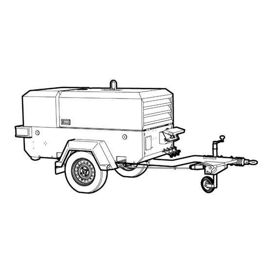
- Page 13 GENERAL INFORMATION 7/53 FIXED HEIGHT RUNNING GEAR 7/53 VARIABLE HEIGHT RUNNING GEAR 7/53, 7/53R...
- Page 14 GENERAL INFORMATION 7/53+ FIXED HEIGHT RUNNING GEAR 7/53+ VARIABLE HEIGHT RUNNING GEAR 7/53, 7/53R...
- Page 15 GENERAL INFORMATION 7/53R FIXED HEIGHT RUNNING GEAR 7/53R VARIABLE HEIGHT RUNNING GEAR 7/53, 7/53R...
- Page 16 GENERAL INFORMATION 7/53R FIXED HEIGHT RUNNING GEAR 7/53R VARIABLE HEIGHT RUNNING GEAR 7/53, 7/53R...
- Page 17 GENERAL INFORMATION 7/53 PERMANENT SKID MOUNTED 7/53 TRUCK SKID MOUNTED 7/53, 7/53R...
- Page 18 GENERAL INFORMATION 7/53+ PERMANENT SKID MOUNTED 7/53+ TRUCK SKID MOUNTED 7/53, 7/53R...
- Page 19 2127 3340 2315 3545 7/53+ Variable 2013 1360 1220 1138 1430 1205 Height - braked 2492 3705 1979 3019 7/53R Fixed Height 1851 1280 1220 1430 1205 - braked 1996 3073 1989 3113 7/53R Variable 1851 1280 1220 1430 1205...
-
Page 20: General Information
7/53R: 7,2 kN (1619 lbs) system including separator / receiver, cooler and pipework must be Maximum vertical coupling load flushed clear of the first fill fluid and new Doosan oil filters installed. (nose weight). 7/53: 100 kg (220 lbs) When this has been completed, the following oils are approved: 7/53R: 75 kg (165 lbs) a) for ambient temperatures above -23°C(-9°F),... -
Page 21: Operating Instructions
Before towing the unit during the hours of darkness, bar pressure then it is recommended that safety retaining wires ensure that the lights are functioning correctly (where fitted). are used on the hoses. Ensure that all transport and packing materials are discarded. 7/53, 7/53R... -
Page 22: Prior To Starting
7. CAUTION: Do not operate the machine with the canopy/doors in the open position as this may cause overheating and operators to be exposed to high noise levels. 8. Check the radiator coolant level (with the unit level). 7/53, 7/53R... - Page 23 Warning lamp, High engine coolant temperature Main switch Warning lamp, low engine fuel level Air pressure gauge (not used for 7/53 and 7/53R) Hourmeter Warning lamp, low battery voltage Warning lamp, low engine oil pressure Warning lamp, high airend discharge temperature...
-
Page 24: Starting The Machine
CAUTION: Never allow the machine to stand idle with pressure in the system. • Do not allow lubricants or coolants to be released into land surfaces or drains. • Do not dispose of a complete machine without documentation 7/53, 7/53R... -
Page 25: Compressor Mounting
Contact your Portable Power representative for flexible mounting kits. Dust and dirt, high humidity, and high temperatures will affect lubricant life and service intervals for components such as inlet air filters, oil separation elements and oil filters. 7/53, 7/53R... -
Page 26: Maintenance
= Check and replace if required decrease in maintenance intervals. = Grease and check Contact your Doosan Infracore Portable Power dealer for more information or assistance in determining the optimum intervals for = Check and adjust if required your application. - Page 27 = Grease and check Contact your Doosan Infracore Portable Power dealer for more information or assistance in determining the optimum intervals for = Check and adjust if required your application.
-
Page 28: Routine Maintenance
(e.g. pressurised components, heated oil. The switch should operate at 120°C. Refit the switch. electrically live components, removed panels, covers and guards, extreme temperatures, inflow and outflow of air, intermittently moving parts, safety valve discharge etc.). 7/53, 7/53R... -
Page 29: High Coolant Temperature Switch
WARNING: Follow the instructions provided by the antifreeze should be changed immediately. Refer to LUBRICATION later in this supplier when adding or draining the antifreeze solution. It is section. advisable to wear personal protective equipment to prevent skin and eye contact with the antifreeze solution. 7/53, 7/53R... -
Page 30: Air Filter Elements
CHART for frequency) and re-tightened where necessary. Refer to the TORQUE SETTING TABLE later in this section. FUEL FILTER WATER SEPARATOR If the fuel filter water separator contains a filter element, it should be replaced at regular intervals (see the SERVICE/MAINTENANCE CHART). 7/53, 7/53R... -
Page 31: Brakes
Slight dragging noises that do not impede the free movement of the wheel are permissible. This adjustment procedure must be carried out as described on both wheel brakes. When the brake has been adjusted accurately the actuating distance is approximately 5-8mm on the cable [11] 7/53, 7/53R... -
Page 32: Running Gear Wheel Bearings
COMPRESSOR LUBRICATING OIL Excessive operation of the handbrake lever, which may have been caused by worn brake linings, must not be corrected by re-adjusting (shortening) the brake linkage [7] Refer to the SERVICE/MAINTENANCE CHART in this section for service intervals. 7/53, 7/53R... -
Page 33: Compressor Oil Filter Element
• Compressor Oil Filter/s - fill with Doosan compressor fluid PRO- is stopped and the system has been completely relieved of all air TEC, XHP605 or XHP405. -
Page 34: Speed & Pressure Regulation Adjustment
Inspect the throttle arm on the engine governor to see that it is extended in the full speed position when the engine is running at full- load speed and the service valve is fully open. (Refer to the GENERAL INFORMATION section of this manual). 7/53, 7/53R... - Page 35 Running gear rear to chassis 63-69 82-93 Running gear drawbar to axle 29-35 39-47 Separator tank cover 40-50 54-68 Separator tank to frame 18-22 24-30 Service pipe (-20jic) 106-133 143-180 Sight glass 40-50 54-68 Wheel nuts 62-70 85-95 7/53, 7/53R...
-
Page 36: Compressor Lubrication
XHP 405 ISO Viscosity Grade 68 Group 3 or 5 with Doosan preferred fluids - the use of these fluids with original Doosan rust and oxidisation branded filters can extend airend warranty. Refer to operator’s manual warranty section for details or contact your Portable Power inhibitors, designed representative. - Page 37 MAINTENANCE 7/53, 7/53R...
-
Page 38: Electrical System
ELECTRICAL SYSTEM 7/53, 7/53R... - Page 39 Crank relay Engine heater relay Contactor (Option) Warm up button Oil pressure switch (Option) Mini controller Fuel solenoid Warm up solenoid (Option) Generator speed solenoid (Option) Keyswitch Generator switch (Option) Airend temperature switch Airend temperature switch Water temperature switch 7/53, 7/53R...
- Page 40 ELECTRICAL SYSTEM 7/53, 7/53R...
- Page 41 ELECTRICAL SYSTEM IQ restriction switch (Option) Mini controller Low fuel switch (Option) Airend temperature Engine oil pressure Engine temperature Low fuel (Option) No charge IQ filter restriction (Option) 7/53, 7/53R...
- Page 42 Fog light Pink SL LH Stop light - left hand Brown SL RH Stop light - right hand Orange TL LH Tail light - left hand Purple TL RH Tail light - right hand Plug Grey Blue White Yellow 7/53, 7/53R...
- Page 43 Reverse light Brown SL LH Stop light - left hand Orange SL RH Stop light - right hand Purple TL LH Tail light - left hand TL RH Tail light - right hand Grey Plug Blue White Yellow 7/53, 7/53R...
-
Page 44: Piping & Instrumentation System
PIPING AND INSTRUMENTATION SYSTEM Air discharge Sonic orifice (restricts flow) Pressure gauge Air/oil Separator tank Safety valve Compressor Engine Oil cooler Oil filter Thermostatic valve (Where fitted) Separator filter assembly (spin-on) 7/53, 7/53R... -
Page 45: Fault Finding
Check the restriction indicators and replace the element(s) if necessary. High pressure air escaping. Check for leaks. Incorrectly set regulation system. Reset the regulation system. Refer to SPEED AND PRESSURE REGULATION ADJUSTMENT in the MAINTENANCE section of this manual. 7/53, 7/53R... - Page 46 Top up the oil level and check for leaks. Dirty or blocked oil cooler. Clean the oil cooler fins. Incorrect grade of oil. Use Doosan recommended oil. Recirculation of cooling air. Move the machine to avoid recirculation. Faulty temperature switch.
-
Page 47: Options
With engine stopped, ensure pressure is relieved from air system. • Remove any hose connected to the water separator housing. Inspect fittings and hoses for any blockage. Clean if necessary. • Remove and clean the water separator float. FIGURE 2. FIGURE 3. 7/53, 7/53R... - Page 48 OPTIONS WATER SEPARATOR MAINTENANCE FIGURE 4. FIGURE 1. FIGURE 5. FIGURE 2. FIGURE 3. 7/53, 7/53R...
-
Page 49: Safety
CAUTION: Blockage of the condensate will result in flooding of the vessels. If flooding occurs, excessive condensate may enter the air stream and could result in damage to downstream equipment. NOTICE: Do not operate at temperatures less that 2° C (35°F). FIGURE 6. 7/53, 7/53R... -
Page 50: Draining Of Machine Fluids
When fitted with bund, the machine must only be operated when level. Drains for engine coolant, engine oil and compressor oil, fuel tank and bunded base drains are located at the left rear side of the machine. Bunded based to be drained daily 7/53, 7/53R... -
Page 51: Operating Instructions
When connecting electrical equipment to any of the socket outlets, it is recommended that the appropriate MCB is in the OFF position before making the connection, switching the MCB to the ON position immediately prior to using the equipment. 7/53, 7/53R... -
Page 52: Starting The Machine
The relieved from the system by means of the service valve(s). ELCB should trip to the off (down) position. CAUTION: Never allow the machine to stand idle with pressure in the system. 7/53, 7/53R... - Page 53 (Refer to section 4 output. General Information). Drive belt is not Re-tension the drive belt. tensioned correctly. Drive pulley is Check the drive pulley and tighten loose on the as required. drive shaft. 7/53, 7/53R...
- Page 54 Circuit breaker 63A Circuit breaker 32A Circuit breaker 16A Circuit breaker 16A Fuse 1A Fuse 1A Alternator - 1 phase Earth stud Contactor Connector - voltmeter Connector - general enable switch Socket outlet 32A/110V Socket outlet 16A/110V Socket outlet 16A/110V 7/53, 7/53R...
- Page 55 CB1/ Circuit breaker 32A Circuit breaker 16A Circuit breaker 16A Fuse 1A Fuse 2A Alternator - 1 phase Earth stud Contactor Connector - voltmeter Connector - generator enable switch Socket outlet 32A/230V Socket outlet 16A/230V Socket outlet 16A/230V 7/53, 7/53R...
- Page 56 CB1/ Circuit breaker 10A Circuit breaker 10A Circuit breaker 10A Fuse 1A Fuse 1A Alternator - 3 phase Earth stud Contactor Connector - voltmeter Connector - generator enable switch Socket outlet 16A/400V Socket outlet 16A/230V Socket outlet 16A/230V 7/53, 7/53R...
-
Page 57: Fault Finding
(Refer STOPPING UNIT OPERATING INSTRUCTIONS section of this manual). CAUTION: If the nylon tubes to the lubricator are disconnected then ensure that each tube is re-connected in its original location. 7/53, 7/53R... -
Page 58: Description
When using this setting procedure it may be found that the engine occasionally shuts down during the normal operation. If so, turn the adjuster clockwise by a further one half turn. 7. Ensure the adjuster locknut is fully tightened. 7/53, 7/53R... -
Page 59: Description
Virtually all legislation regarding the operation of a diesel engine in a hazardous area includes a mandatory requirement to fit a tested and approved exhaust spark arrestor. 7/53, 7/53R... -
Page 60: General Information
Removal or failure of this heat protection may cause canopy heat damage. Do not use high pressure water jet cleaning directly at the decals area. It may cause damage or removal of the decals. 7/53, 7/53R... -
Page 61: Parts Ordering
NOTICE HOW TO ORDER Doosan can bear no responsibility for injury or damages resulting directly from the use of non-approved repair parts. The satisfactory ordering of parts by a purchaser is greatly dependent Doosan Infracore service facilities and parts are available worldwide. - Page 62 The company makes no other warranty or representation of any kind whatsoever, expressed or implied, except that of title, and all implied Doosan offers an airend exchange program to benefit portable warranties, including any warranty of merchantability and fitness for a compressor users.
- Page 64 Doosan Bobcat EMEA s.r.o U Kodetky 1810 263 12 Dobříš Czech Republic www.doosanportablepower.eu...
Need help?
Do you have a question about the 7/53R and is the answer not in the manual?
Questions and answers