Advertisement
Quick Links
OPERATION and MAINTENANCE
This manual contains important safety information.
Do not destroy this manual.
This manual must be available to the personnel who operate and maintain this compressor.
Doosan Infracore Portable Power
1293 Glenway Drive
Statesville, N.C. 28625
DoosanPortablePower.com
Book: 46497806 (9/2013) Rev D
MANUAL
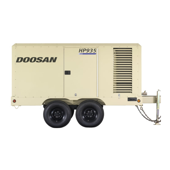
COMPRESSOR MODEL
HP935WCU (708)
XP1050WCU (709)
HP935WCU-EX (E78)
XP1050WCU-EX (E80)
Advertisement

Related Manuals for Doosan HP935WCU


Summary of Contents for Doosan HP935WCU
- Page 1 XP1050WCU-EX (E80) This manual contains important safety information. Do not destroy this manual. This manual must be available to the personnel who operate and maintain this compressor. Doosan Infracore Portable Power 1293 Glenway Drive Statesville, N.C. 28625 DoosanPortablePower.com Book: 46497806 (9/2013) Rev D...
- Page 3 QUALITY POLICY We will supply products and services that consistently meet the requirements of our customers and each other. Book 46497806 (2/09)
- Page 4 FOREWORD The contents of this manual are considered to be proprietary and confidential to Doosan Infracore Portable Power (herein referred to as “Portable Power”). Nothing contained in this document is intended to extend any promise, warranty or representation, expressed or implied, regarding the Portable Power products described herein.
- Page 5 The purpose of this manual is to train the operator with functions, operation, and basic service and maintenance requirements of the compressor. During the preparation of this manual, every effort was made to ensure the adequacy and accuracy of the contents. Your Portable Power dealer will assist with setup and initial startup of the compressor.
- Page 6 TABLE OF CONTENTS SECTION 1 ....SAFETY SECTION 2 ....FOREWORD SECTION 3 ....GENERAL DATA SECTION 4 .
- Page 7 SECTION 1- - SAFETY SAFETY PRECAUTIONS Compressed air must not be used for a feed to any form of breathing apparatus or mask. General Information The discharged air contains a very small percentage Ensure that the operator reads and understands the of compressor lubricating oil and care should be taken decals and consults the manuals before maintenance to ensure that downstream equipment is compatible.
- Page 8 This machine may include such materials as oil, diesel Use care to avoid contacting hot surfaces (engine fuel, antifreeze, brake fluid, oil/air filters and batteries exhaust manifold and piping, air receiver and air which may require proper disposal when performing discharge piping, etc.).
- Page 9 SAFETY LABELS Look for these signs on machines shipped to international markets outside North America, which point out potential hazards to the safety of you and others. Read and understand thoroughly. Heed warnings and follow instructions. If you do not understand, inform you supervisor. Hot Surface Corrosion risk Lifting point...
- Page 10 Read the Operation and Maintenance manual before operation or maintenance of this machine is undertaken. WARNING - - Maintain correct tire pressure. (Refer to the GENERAL INFORMATION section of this manual). WARNING: Consult the operation and maintenance manual before performing any maintenance. Rough Service Designation Wet Location Operation Do not stack...
- Page 11 Oil Drain km/h WARNING undertake Do not exceed the speed limit. maintenance on this machine until the electrical supply is disconnected and the air pressure is totally relieved. Read the Operation and Maintenance manual before operation or maintenance of this machine is undertaken Do not remove the Operating and Maintenance manual and manual holder from this machine.
- Page 12 Look for these signs on machines shipped to markets in North America, which point out potential hazards to the safety of you and others. Read and understand thoroughly. Heed warnings and follow instructions. If you do not understand, inform you supervisor. Indicates the presence of a hazard which WILL cause serious injury, death or property damage, if ignored.
- Page 13 km/h WARNING WARNING Improper operation of this equipment. Collapsing jackstand. Can cause serious injury or death. Can cause serious injury. Read Operator’s Manual supplied with this machine before operation or Insert locking pin completely. servicing. Excessive towing speed. Modification or alteration of this machine. Can cause serious injury or death.
- Page 14 CAUTION WARNING DO NOT USE ETHER. High pressure air. Can cause serious ENGINE DAMAGE WILL OCCUR. injury or death. This engine is equipped with an Relieve pressure before electric heater starting aid. removing filler plugs/caps, fittings or covers. NOTICE COOLANT FILL INSTRUCTIONS Adding: USE DIESEL Remove radiator cap.
- Page 15 SECTION 3 - - GENERAL DATA Model HP935WCU XP1050WCU Rated Delivery: 1050 litres/sec Rated Pressure: - - psi - - kPa 1034 Safety Valve Setting: - - psi - - kPa 1379 1379 Engine Model: M11- -335 M11- -335 Cummins AMBIENT OPERATING RANGE .
- Page 16 SECTION 4 - - OPERATING INSTRUCTIONS OPERATING CONTROLS & INSTRUMENTS Control Panel DIAGNOSTICS/AUTO SHUTDOWN High Compressor Temperature - - 248_F (120_C) or more. 10. Low Engine Oil Pressure - - 12 psi or less 11. High Engine Temperature - - Coolant above 215_F (102_C).
- Page 17 WARNING OPTIMUM OIL LEVEL (EITHER SIDE) YELLOW - - TOO HIGH Do not climb on top of unit. The lifting eye can be reached through the roof door ONLY from INSIDE of the unit. GREEN - - OK DISCONNECT and SET - - UP S Place the unit in an open, well--ventilated area.
- Page 18 S Check the compressor and engine lubricating oil TOWING levels. Tandem Axle Units The oil level should be checked before the unit is started. Always check the oil level while the unit is These units are designed to be highway towable. Do level, the engine off, and there is zero pressure in the NOT exceed 65 mph towing speed.
- Page 19 S In freezing weather, flip HEATERS switch “ON” and CAUTION wait sixty (60) seconds. This applies heat to the control system components for easier starting. Leave this switch “ON” while operating at these temperatures. No smoking, sparks, or open flame near fuel. Check the fuel level.
- Page 20 NOTICE Push the SERVICE AIR button. The engine should Failure to allow turbo cool down prior to stopping go to full speed and the discharge pressure rise to can cause turbocharger damage. slightly over rated pressure. If there is no air being Once the engine stops, the automatic blowdown consumed, the compressor will unload (intake should valve will begin to relieve all pressure from the...
- Page 21 EQUIPMENT PROTECTION Refer OPERATING CONTROLS INSTRUMENTS for the various problem signal criteria ( F, psi, etc.). The indicated problem area should be NOTICE inspected for a physical cause (low fluid, broken fan belt, evidence of excessive heat, etc.) and corrections made.
- Page 22 SECTION 5 - - MAINTENANCE GENERAL Note: The oil level gage will not read properly while the engine is running. In addition to periodic inspections, many of the components in these units require periodic servicing to provide maximum output and performance. Servicing may consist of pre--operation and post--operation OPTIMUM OIL LEVEL procedures to be performed by the operating or...
- Page 23 AIR CLEANER Move the nozzle up and down while rotating the ele- ment. Be sure to keep the nozzle at least one inch This unit is equipped with an AIR FILTERS RESTRICTED lamp on the instrument panel, covering (25.4 mm) from the pleated paper. both the engine and the compressor.
- Page 24 FUEL TANK WARNING This unit is equipped with tank that can be filled from front of unit. Using clean fuel in the fuel tank is vitally High pressure air can cause serious injury or death from hot oil and flying parts. Always relieve important and every precaution should be taken to en- pressure before removing caps, plugs, covers or sure that only clean fuel is either poured or pumped...
- Page 25 The engine cooling system is filled at the factory with a COMPRESSOR OIL COOLER 50/50 mixture of water and ethylene glycol. This permanent type antifreeze contains rust inhibitors and The compressor lubricating and cooling oil is cooled provides protection to --35 F (--37 C). The use of such by means of the fin and tube--type oil cooler, located a mixture is recommended for both summer and winter beside the radiator.
- Page 26 COMPRESSOR OIL The lubricating and cooling oil must be replaced every The flexible hoses used in the fuel, oil and air lines on 1000 hours of operation or six (6) months, whichever these units are primarily used for their ability to accom- comes first.
- Page 27 RUNNING GEAR If bearing adjustment is required or the hub has been Every month or 500 miles, tighten the wheel lug nuts to removed for any reason, the following procedure must 85 -- 95 lbs.--ft. Every six months the wheel bearings, be followed to ensure a correct bearing adjustment of grease seals and axle spindles should be inspected 0.001 to .012 free play.
- Page 28 * Open service valve and manual blowdown valve * Remove (20) cover mounting screws. at end of machine. * Ensure pressure is relieved, with BOTH: * Remove cover, element and inner shell. - - Discharge air pressure gauge reads zero (0). * Remove any gasket material left on cover or tank.
- Page 29 cut line if necessary NOTICE SCAVENGE LINE Excessive oil carry- -over may be caused by an oil- - logged separator element. Do not replace element WARNING without first performing the following mainte- nance procedure: High pressure air can cause serious injury or death from hot oil and flying parts.
- Page 30 Apply 2 medium -- wet coats of Duponts 222S Adhesion Promoter over the entire area to be EXTERIOR FINISH CARE painted, with a 5 minute flash in between coats. This unit was painted and heat cured at the factory To apply the texture coat, use Duponts 1854S with a high quality, thermoset polyester powder Tuffcoat Primer.
- Page 31 BRAKE SYSTEMS (Hydraulic Only) Whenever a brake line hose, tube or fitting is removed/ This compressor is equipped with mechanical parking replaced, the hydraulic brake system must be bled of brakes and hydraulic surge brakes. The maintenance air to ensure proper brake operation. Bleed the of these brake systems is required to ensure safe op- brakes, at each wheel cylinder, in the following order: eration of this compressor.
- Page 32 NOTE: New cables will stretch and therefore should be readjusted after the first week of use. Every six months, apply a multi--purpose grease to the fittings on the brake actuator. Electric Brake Adjustment: Brakes should be adjusted (1) after the first 200 miles of operation when the brake shoes and drums have “seated”, (2) at 3000 mile intervals, (3) or as use and performance requires.
- Page 33 MAINTENANCE SCHEDULE These time periods should be reduced if operating in extreme conditions (very hot, cold, dusty or wet). Daily Weekly Monthly 3 MOS . 6 MOS. 12 MOS. LARGE UNITS 500 hours 1000 hours 2000 hours **Hydraulic Oil Level Compressor Oil Level Engine Oil Level **Radiator Coolant Level...
- Page 34 SECTION 6 - - LUBRICATION GENERAL INFORMATION Lubrication is an essential part of preventive mainte- If the unit has been operated for the time/ hours men- nance, affecting to a great extent the useful life of the tioned above, it should be completely drained of oil. If unit.
- Page 35 Portable Compressor Fluid Chart Refer to these charts for correct compressor fluid RATED OPERATING PRESSURE required. Note that the selection of fluid is dependent on 350 PSI 100 - - 300 PSI the design operating pressure of the machine and the 125_F ambient temperature expected to be encountered 50_C...
- Page 36 SECTION 7 - - Troubleshooting INTRODUCTION B. Do The Simplest Things First Troubleshooting for a portable air compressor Most troubles are simple and easily corrected. is an organized study of a particular problem or example, most complaints are “low capacity” which may series of problems and a planned method of be caused by too low an engine speed or “compressor procedure for investigation and correction.
- Page 37 TROUBLE SHOOTING CHART Bold Headings depict the COMPLAINT - - Subheadings suggest the CAUSE Note: Subheadings suggest sequence to follow troubleshooting. Corrective Action Unit Shutdown: Out of Fuel Add CLEAN diesel Fuel Compressor Oil Temp. Too High See Complaint 10 Engine Water Temp.
- Page 38 Engine Oil Pressure Lamp Stays On: Corrective Action Low Oil Level Add oil. Out of Level >15 degrees Relocate or reposition. Wrong Lube Oil See Engine Oil Spec. Change oil. Clogged Oil Filter Element(s) Replace element(s). Engine Malfunctioning See Trouble Shooting in Engine Manual. Loose Wire Connection.
- Page 39 Excessive Compressor Oil Temperature: Corrective Action Ambient Temp. > 125_F (52_C) Above spec limit. Out of Level > 15 degrees Relocate or reposition unit. Low Oil Level Add oil. Look for any leaks. Wrong Lube Oil Check spec in this manual. Dirty Cooler Clean exterior surfaces.
- Page 40 Short Air Cleaner Life: Corrective Action Dirty Operating Conditions Move unit to cleaner environment. Inadequate Element Cleaning Install new element. Incorrect Stopping Procedure Read procedure in this manual. Wrong Air Filter Element Install proper element. Oil Pump Drive Coupling Inspect coupling. If necessary, replace coupling. Excessive Oil In Air: High Oil Level Read procedure in this manual.
- Page 41 Revision History Rev. EC Number Comments Original release Updated Cover Doosan reference updates CN026601 Added Export Models to Front Cover CN034865...
- Page 42 Doosan Infracore Portable Power 1293 Glenway Drive Statesville, N.C. 28625 www.doosanportablepower.com ©2012 Doosan Infracore Portable Power Printed in the U.S.A.
Need help?
Do you have a question about the HP935WCU and is the answer not in the manual?
Questions and answers