
Subscribe to Our Youtube Channel
Related Manuals for Bucher Hydraulics VF-iValve VF-i250 Series


Summary of Contents for Bucher Hydraulics VF-iValve VF-i250 Series
- Page 1 Operating Instructions Lift Control Valve VF-iValve – VF-i250… and VF-i500… Issue: 09.2015 1/33 Reference: 300-I-9010546-EN-00 Reference: 300-I-9010546-EN-00 Issue: 03.2015 1/33...
- Page 2 Because the products are subject to continual improvement, we reserve the right to amend the pro duct specifications contained in this catalogue. The original language and legal terminology of all Bu cher Hydraulics documentation is exclusively German. Bucher Hydraulics cannot be held liable for any possible errors in translation.
-
Page 3: Table Of Contents
VF-iValve Lift Control Valve Contents Page ..............About this document . - Page 4 VF-iValve Lift Control Valve ............6.1.1 Surroundings .
-
Page 5: About This Document
VF-iValve Lift Control Valve 1 About this document About this document This commissioning and maintenance manual provides the basis for us VF-iValve – VF-i250 / VF-i500 ing the lift control valve and iCon elec tronic card for its intended purpose in a proper, effective, and safe manner. -
Page 6: Safety Instructions
2 Safety instructions VF-iValve Lift Control Valve Safety instructions This documentation (manual) advises the user of the dangers and re maining risks that can arise even when the product is being used pro perly and for its intended purpose. It is essential to take note of the sa fety instructions in each section. -
Page 7: Example Of A Safety Notice
VF-iValve Lift Control Valve 2 Safety instructions 2.1.3 Example of a safety notice S Pictogram S Signal word S Type and source of danger S Possible consequences of the danger S Measures for preventing the danger WARNING! Dangerous electrical voltage Touching electrical components may result in serious injury or death. -
Page 8: Operator's Obligations
2 Safety instructions VF-iValve Lift Control Valve 2.3.2 Operator's obligations Working with safety in mind S Only operate the valve if it is in perfect technical condition; only use it as intended, staying aware of safety and risks, and adhearing to the instructions in this manual S Ensure that the following are observed and monitored: - adherence to intended use... -
Page 9: Product Description
VF-iValve Lift Control Valve 3 Product description Product description Intended use The VF-iValve intelligent lift control valve is an electronically controlled hydraulic valve block for controlling hydraulic lifts. The VF-iValve is situ ated on the hydraulic power unit and activated by the lift control system. Electronic control is accomplished by an electronic unit –... -
Page 10: Construction And Function
4 Construction and function VF-iValve Lift Control Valve Construction and function IMPORTANT!: Information on schematics and diagrams is avail able in the VF-iValve Planning Information (300-D-9010545). Factory settings Installation specific settings are stored on the ParamCard: S Kit type S Cylinder type and diameter S Max. -
Page 11: Operating Controls And Indicators
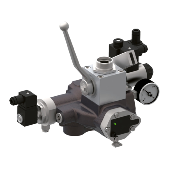
VF-iValve Lift Control Valve 5 Operating controls and indicators Operating controls and indicators VF-iValve lift control valve 5.1.1 Components of the VF-iValve – VF-i250 Legend Solenoid UP/DOWN Connection, sensor cable iBox Pressure relief valve Ball valve Nameplate Solenoid UCM / A3 iBox Slack rope safety device Pump port... -
Page 12: Components Of The Vf-Ivalve - Vf-I500
5 Operating controls and indicators VF-iValve Lift Control Valve 5.1.2 Components of the VF-iValve – VF-i500 Legend Solenoid UP/DOWN Nameplate Pressure relief valve Emergency-lowering valve Ball valve Solenoid VF-Emergency stop Solenoid UCM / A3 valve Hand pump iBox Pressure relief valve for the Pump port hand pump Tank port... -
Page 13: Hand Pump / Emergency Lowering
VF-iValve Lift Control Valve 5 Operating controls and indicators Hand pump / Emergency lowering VF-iValve – VF-i250 The VF-iValve (VF-i250) comes with a combination of hand pump and emergency lowering valve as standard.The car can be moved upward with the hand pump when needed, and downward by means of the emergency-lowering facility. - Page 14 5 Operating controls and indicators VF-iValve Lift Control Valve VF-iValve – VF-i500 In the VF-iValve i500, the hand pump and emergency-lowering facility are separated. The car can be moved upward with the hand pump when needed, and downward by means of the emergency-lowering facility. Hand pump Emergency lowering DANGER!
-
Page 15: Electronic Card Icon With Vf-Board
VF-iValve Lift Control Valve 5 Operating controls and indicators Electronic card iCon with VF-board ATTENTION! Electrostatic discharge (ESD) The iCon can be damaged by incorrect handling. Always keep the iCon in its ESD protective bag and only hold it by the frame. com/meas down m0(9) -
Page 16: Led Indications
5 Operating controls and indicators VF-iValve Lift Control Valve 5.3.1 LED indications Description Function Status Communication with communication with valve ok, data packages properly valve transmitted/received flashes ra no (correct) communication with valve pidly meas Measurement of feed feedback values from valve (flow, pressure, temperature) back values plausible when LED “com”... - Page 17 VF-iValve Lift Control Valve 5 Operating controls and indicators Description Function Status Power supply all monitored voltages within the permissible range flashes ra one of the internally generated voltages outside the permis pidly sible range flashes external supply voltage (+24 V) outside the permissible slowly range Readiness for opera...
-
Page 18: Led Indications (Options Board - Switching Outputs)
5 Operating controls and indicators VF-iValve Lift Control Valve 5.3.2 LED indications (options board – switching outputs) Description Status Function Readiness for operation program running correctly programm not running correctly flashes communication problem with iCon Switching output 3 flashes switching point 3 was under-shot/ ex rapidly ceeded (relay s3 energised) -
Page 19: Installation And Commissioning
VF-iValve Lift Control Valve 6 Installation and commissioning Installation and commissioning Packaging materials must be disposed of in accordance with the gener ally recognised regulations of the respective countries Safety information Before beginning any installation and commissioning work, it is a re quirement that all personnel have read and understood the chapter "Safety instructions". -
Page 20: Electrical Installation
6 Installation and commissioning VF-iValve Lift Control Valve 6.2.2 Electrical installation DANGER! Dangerous voltage Leads to death or serious injuries. Before starting electrical installation works, disconnect all power to the control cabinet. Check whether the 24 V DC output of the lift control meets the requirements of the iCon (see Planning Information 300-D-9010545) When the 24 V DC output of the lift control meets the requirements of... -
Page 21: Installation Of The Paramcard
VF-iValve Lift Control Valve 6 Installation and commissioning 6.2.3 Installation of the ParamCard The ParamCard is a memory card which stores installation specific para meters and data. The ParamCard is plugged onto the iCon. There is no travel without ParamCard. If the iCon needs to be replaced the ParamCard will be pulled off the old iCon and plugged onto the new iCon. - Page 22 6 Installation and commissioning VF-iValve Lift Control Valve ATTENTION! Note: Always quote the serial no. when making enquiries. This makes it easier for the factory to help you! Note: The serial numbers on the ParamCard and the VF-iValve must be the same to avoid the need for resetting. Detach the ParamCard (C) from the Quality-Certificate Read the serial no.
-
Page 23: Hydraulic Fluids And Oil Additives
The volume of oil additive that is mixed in must not exceed 2% of the existing total oil volume. Bucher Hydraulics cannot guarantee the proper functioning of the lift control valve if other additives are used or if the maximum permissible amount of the above additives is exceeded. -
Page 24: Positioning Of The Deceleration Switches
6 Installation and commissioning VF-iValve Lift Control Valve 6.2.5 Positioning of the deceleration switches IMPORTANT!: Information on "Positioning the deceleration switches" is available in the Planning Information publication 300-D-9010545. 6.2.6 Check/setting of the max. operating pressure (EN 81-2, art. 12.5.3) VF-i250 To check the minimum load static pressure (with empty car): Read the minimum load static pressure on the pressure gauge... -
Page 25: Safety Checks
VF-iValve Lift Control Valve 6 Installation and commissioning Safety checks 6.3.1 Test of the monitoring of the UCM/A3-valve Testing the monitoring of the UCM/A3 valve (⇒ see Planning Informa tion) can be carried out using two different methods. Test with Handterminal The iCon-firmware includes two functions (“Test SMA GND”... - Page 26 6 Installation and commissioning VF-iValve Lift Control Valve Issue the command for another travel The lift must refuse to execute further travels until the SMA-error is reset on the lift control. Reset the SMA-error on the lift control Disconnect the 24 V supply from the input “Monitoring UCM / A3-valve”...
-
Page 27: Pipe Rupture Valve Test
VF-iValve Lift Control Valve 6 Installation and commissioning 6.3.2 Pipe rupture valve test A precondition for testing the pipe-rupture valve is that the lift must be working properly, without any faults. DANGER! Uncontrolled descent (free fall) Leads to death or serious injuries. Before testing the pipe-rupture valve, make sure that there are no people or materials in the lift shaft. - Page 28 6 Installation and commissioning VF-iValve Lift Control Valve Carrying out Pipe rupture valve test with Handterminal On the Handterminal select menu 3, then “Adjust./tests”, then “Pipe rupt. test” Various LEDs start to flicker (at high frequency = fast). On the iCon press and hold the push buttons ”ok” and “select” Send DOWN command Wait until the car is accelerating The LED ”down“...
-
Page 29: Maintenance
VF-iValve Lift Control Valve 7 Maintenance Maintenance Maintenance schedule This service plan is just a guide. Adjustments or changes should be un dertaken by the installer. Work to be carried out Time Valve Check error memory Check internal leakage Check external leakage Check the maximum pressure setting (pressure relief valve/ maximum-pressure setscrew) -
Page 30: Maintenance Work
7 Maintenance VF-iValve Lift Control Valve Maintenance work 7.2.1 Pilot filter The Filter-strainer of the pilot valve is positioned in accordance with the international standards for lifts (EN 81.2 art. 12.5.7). CAUTION! Contamination in valve (filter) Severe malfunction possible. People may suffer injury and materials may be damaged. - Page 31 VF-iValve Lift Control Valve 7 Maintenance For VF-i250 only Switch the main switch OFF Close the ball valve (1) Turn the slack rope safety device (2) by 90° clockwise. (see Chapter 5.2) Push the extension lever onto the lever stub (3) of the hand pump as far as it will go, then retract by approx.
- Page 32 7 Maintenance VF-iValve Lift Control Valve In order to replace the filter strainer (9): Pinch the o-ring (10) between the tips of forefinger and thumb Push the o-ring (10) off the solenoid tube (8) with the thumb of the other hand Pull the filter strainer (9) off the solenoid tube (8) Push the new filter strainer (9) onto the solenoid tube (8) Insert the new o-ring (10) into the groove of the solenoid tube (8)
-
Page 33: Repair
VF-iValve Lift Control Valve 8 Repair Repair Troubleshooting and clearing faults IMPORTANT!: Additional information on troubleshooting / fault di agnosis and fault clearing is available in the Parametrisation and Maintenance Manual in the LOGintern area of our homepage www.bucherhydraulics.com. => see Section 1.3 "Other applicable documents" Issue: 09.2015 33/33 Reference: 300-I-9010546-EN-00...
Need help?
Do you have a question about the VF-iValve VF-i250 Series and is the answer not in the manual?
Questions and answers