
Related Manuals for Lorentz PV Combiner 1000-125-4

Summary of Contents for Lorentz PV Combiner 1000-125-4
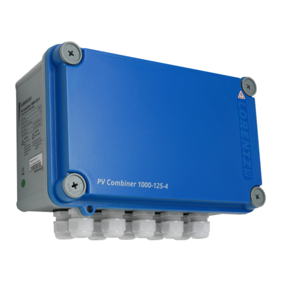
- Page 1 PV Combiner 1000-125-4 Connection Box for parallel wiring Manual for Installation and Operation The Solar Water Pumping Company...
-
Page 2: Table Of Contents
Technical Data ........6 Further related LORENTZ products .......6 ƒ... -
Page 3: Safety Instructions
Should the available personnel be lacking the and assembly work is performed exclusively by Scope of delivery of the PV Combiner 1000-125-4: necessary qualification, they must be trained and authorized and qualified experts sufficiently Explanation of Warning Symbols instructed accordingly. -
Page 4: Product Description
7.2.1 PV Disconnect 1000-50-5 (Item No. 19-001965) 7.2.2 PV Combiner 1000-15-3-F (Item No. 19-001940) and PV Combiner 1000-15-6-F (Item No. 19-001945) The LORENTZ PV Combiner 1000-125-4 is a PV ƒ Parallel wiring for 4 DC Inputs The LORENTZ PV Disconnect 1000-50-5 is a PV... -
Page 5: Pv Wiring Diagram For Psk Pump Systems
7.2.3 PV Protect 1000-125 (Item no.: 19-001970) 15-3-F: The PV Protect 1000-125 will provide an enhanced Figure 5: Example of PV wiring diagram for the PV Combiner 1000-125-4 using a PV Disconnect 1000-50-5 level of protection from electrical surges (for and a PV Protect 1000-125 . -
Page 6: Installation
PV Wiring diagram for PSk Pump Systems Installation 9 Installation Figure 6: Example of PV wiring diagram for the PV Combiner 1000-125-4 using two PV Combiner 1000-15-6-F, Figure 7: PV Combiner 1000-125-4 (Front view): two PV Disconnect 1000-50-5 and a PV Protect 1000-125: "Installation where Fuses are required"... - Page 7 To access the clamping terminals, open the lid of the housing and unscrew the touch protection (4x plastic 9.2.3 Wiring Connection ƒ Note: The PV Combiner 1000-125-4 is shipped screws, PH3): with a plastic bag containing smaller rubber ƒ DC Input Cables (coming from PV Disconnect...
- Page 8 If the pump does not run of solar powered water pumping. Today LORENTZ is active in over 130 WARNING – Before connecting the Most problems are caused by wrong connections countries through a dedicated network PV Modules to each other make sure that (in a new installation) or failed connections.
Need help?
Do you have a question about the PV Combiner 1000-125-4 and is the answer not in the manual?
Questions and answers