
Related Manuals for Hobart Welders Handler 125


Summary of Contents for Hobart Welders Handler 125
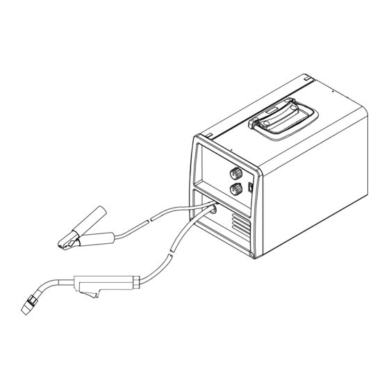
- Page 1 OM-947 212 149B June 2004 Processes Flux Cored (FCAW) Welding MIG (GMAW) Welding (Optional) Description Arc Welding Power Source And Wire Feeder Handler 125 / 125 MIG And H-9A Gun...
- Page 2 System Standard. business. are also provided. Hobart Welders manufactures a full line of welders and welding related equipment. For information on other quality Hobart products, contact your local Hobart distributor to receive the latest full line catalog or individual catalog sheets.
-
Page 3: Table Of Contents
TABLE OF CONTENTS SECTION 1 − SAFETY PRECAUTIONS - READ BEFORE USING ....... . . 1-1. - Page 4 TABLE OF CONTENTS SECTION 7 − WIRE WELDING GUIDELINES ........... 7-1.
-
Page 5: Section 1 − Safety Precautions - Read Before Using
SECTION 1 − SAFETY PRECAUTIONS - READ BEFORE USING som _nd_4/98 1-1. Symbol Usage Means Warning! Watch Out! There are possible hazards with this procedure! The possible hazards are shown in the adjoining symbols. This group of symbols means Warning! Watch Out! possible Y Marks a special safety message. - Page 6 ARC RAYS can burn eyes and skin. BUILDUP OF GAS can injure or kill. D Shut off shielding gas supply when not in use. Arc rays from the welding process produce intense visible and invisible (ultraviolet and infrared) rays D Always ventilate confined spaces or use that can burn eyes and skin.
-
Page 7: Additional Symbols For Installation, Operation, And Maintenance
1-3. Additional Symbols For Installation, Operation, And Maintenance FIRE OR EXPLOSION hazard. MOVING PARTS can cause injury. D Do not install or place unit on, over, or near D Keep away from moving parts such as fans. combustible surfaces. D Keep all doors, panels, covers, and guards D Do not install unit near flammables. -
Page 8: Emf Information
1-5. EMF Information Considerations About Welding And The Effects Of Low Frequency 1. Keep cables close together by twisting or taping them. Electric And Magnetic Fields 2. Arrange cables to one side and away from the operator. Welding current, as it flows through welding cables, will cause electro- magnetic fields. -
Page 9: Section 1 − Consignes De Securite − Lire Avant Utilisation
SECTION 1 − CONSIGNES DE SECURITE − LIRE AVANT UTILISATION som _nd_fre 4/98 1-1. Signification des symboles Signifie Mise en garde ! Soyez vigilant ! Cette procédure présente des risques de danger ! Ceux-ci sont identifiés par des symboles adjacents aux directives. Ce groupe de symboles signifie Mise en garde ! Soyez vigilant ! Il y a des Y Identifie un message de sécurité... - Page 10 LES RAYONS DE L’ARC peuvent pro- LES ACCUMULATIONS DE GAZ ris- voquer des brûlures dans les yeux et quent de provoquer des blessures ou sur la peau. même la mort. Le rayonnement de l’arc du procédé de soudage D Fermer l’alimentation du gaz protecteur en cas de génère des rayons visibles et invisibles intenses non utilisation.
-
Page 11: Dangers Supplémentaires En Relation Avec L'installation, Le Fonctionnement Et La Maintenance
1-3. Dangers supplémentaires en relation avec l’installation, le fonctionnement et la maintenance Risque D’INCENDIE OU DES ORGANES MOBILES peuvent D’EXPLOSION. provoquer des blessures. D Ne pas placer l’appareil sur, au-dessus ou à proxi- D Rester à l’écart des organes mobiles comme le mité... -
Page 12: Principales Normes De Sécurité
1-4. Principales normes de sécurité Safety in Welding and Cutting, norme ANSI Z49.1, de l’American Wel- Safe Handling of Compressed Gases in Cylinders, CGA Pamphlet P-1, ding Society, 550 N.W. Lejeune Rd, Miami FL 33126 de la Compressed Gas Association, 1235 Jefferson Davis Highway, Suite 501, Arlington, VA 22202. -
Page 13: Section 2 − Specifications
SECTION 2 − SPECIFICATIONS 2-1. Specifications Amperes Input at Maximum Open- Rated Welding Amperage Weight Overall Rated Load Output Circuit Voltage Output Range 115 V, 60 Hz, Single- W/ Gun Dimensions Phase Length: 16-7/8 in (429 mm) 90 A @ 19 Volts DC, 2.90 2.50 20% Duty Cycle... -
Page 14: Volt-Ampere Curves
2-3. Volt-Ampere Curves The volt-ampere curves show the 33.0 minimum and maximum voltage and amperage output capabilities of the welding power source. Curves of other settings fall between the curves shown. 28.0 23.0 18.0 13.0 10.0 20.0 30.0 40.0 50.0 60.0 70.0 80.0 90.0 100.0 110.0 120.0 130.0 Amperage Range 1 Range 2... -
Page 15: Changing Polarity
3-3. Changing Polarity Lead Connections For Direct Current Electrode Negative (DCEN) Lead Connections For Direct Current Electrode Positive (DCEP) Always read and follow wire manufacturer’s recommended po- larity, and see Section 3-2. Close door. Ref. 210 428 3-4. Installing Gas Supply NOTE This Section only applies to MIG units or units equipped with MIG kit. -
Page 16: Installing Wire Spool And Adjusting Hub Tension
3-5. Installing Wire Spool And Adjusting Hub Tension Installing 4 in (102 mm) Wire Spool When a slight force is needed to turn spool, tension is set. Installing 8 in (203 mm) Wire Spool Adapter used with Only applies to units equipped with 8 in (203 mm) optional hub kit. -
Page 17: Selecting A Location And Connecting Input Power For 115 Vac Model
3-6. Selecting A Location And Connecting Input Power For 115 VAC Model Rating Label Grounded Receptacle A 115 volt, 20 ampere individual branch circuit protected by time-de- lay fuses or circuit breaker is re- quired. Plug From Unit Select extension cord of 14 AWG for up to 50 ft (15 m) or 12 AWG for 50 up to 200 ft (61 m). -
Page 18: Threading Welding Wire
3-7. Threading Welding Wire Wire Spool Welding Wire Inlet Wire Guide Pressure Adjustment Knob Drive Roll Gun Cable Lay gun cable out straight. Tools Needed: Hold wire tightly to keep it from unraveling. 6 in 4 in (150 mm) (102 mm) Open pressure assembly. -
Page 19: Section 4 − Operation
SECTION 4 − OPERATION 4-1. Controls Voltage Switch Use control to select the weld voltage range. As the thickness of material increases, a higher voltage range must be selected (see weld setting label in welding power source Section applicable). Do not switch under load. -
Page 20: Weld Parameter Chart
4-2. Weld Parameter Chart OM-947 Page 16... - Page 21 210 428 OM-947 Page 17...
-
Page 22: Section 5 − Maintenance &Troubleshooting
SECTION 5 − MAINTENANCE &TROUBLESHOOTING 5-1. Routine Maintenance Y Disconnect power before maintaining. 3 Months Replace Repair or Clean unreadable replace tighten weld labels. cracked terminals. weld cable. 6 Months Blow out or vacuum inside. During heavy service, clean monthly. 5-2. -
Page 23: Changing Drive Roll Or Wire Inlet Guide
5-4. Changing Drive Roll Or Wire Inlet Guide Pressure Adjustment Knob Pressure Assembly Pivot pressure adjustment knob down, and lift pressure assembly Pivot Tube Plate Securing Screws Pressure Arm Pivot Tube Inlet Wire Guide Remove screws and pivot tube plate. Lift out pressure arm pivot tube, and slide inlet wire guide out of tube. -
Page 24: Replacing Gun Contact Tip
5-5. Replacing Gun Contact Tip Y Turn power before replacing contact tip. Tip Adapter Contact Tip Nozzle Cut off welding wire at contact tip. Remove nozzle. Remove contact tip from tip adapter and install new contact tip. Reinstall nozzle. Tools Needed: OM-947 Page 20... -
Page 25: Cleaning Or Replacing Gun Liner
5-6. Cleaning Or Replacing Gun Liner Y Turn off welding power source. Tools Needed: Head 8 mm / 10 mm Tube 8 mm Remove nozzle. Cut off wire Open pressure assembly. Retract Hold wire tightly to keep it at contact tip, and remove wire from liner onto spool. - Page 26 5-6. Cleaning Or Replacing Gun Liner (Continued) 13/16 in (21 mm) 8 mm When liner exits cable at gun handle, guide liner into head tube. Continue to push liner until it exits end of head tube. Insert retaining nut into adapter, and adjust liner stickout as shown.
-
Page 27: Replacing Switch And/Or Head Tube
5-7. Replacing Switch And/Or Head Tube Y Turn Off welding power source. Separate gun handle by lifting top rear portion up and sliding Twist handle locking ring forward over head tube. counterclockwise 1/4 turn and slide it down cable. Slide trigger assembly forward and out of lower portion of handle. -
Page 28: Troubleshooting Table
5-8. Troubleshooting Table Trouble Remedy Secure power cord plug in receptacle (see Section 3-6). No weld output; wire does not feed; fan does not run does not run. Replace building line fuse or reset circuit breaker if open. Place Power switch in On position (see Section 4-1). Reset welding power source circuit breaker if open. -
Page 29: Section 6 − Electrical Diagram
SECTION 6 − ELECTRICAL DIAGRAM 210 513 Figure 6-1. Circuit Diagram OM-947 Page 25... -
Page 30: Section 7 − Wire Welding Guidelines
SECTION 7 − WIRE WELDING GUIDELINES 7-1. Typical FCAW Process Connections Y Weld current can damage electronic parts in vehicles. Disconnect both battery cables before welding on a vehicle. Place work clamp as close to the weld as possible. Wire Feeder/ Power Source Work Clamp Workpiece... -
Page 31: Typical Control Settings
7-3. Typical Control Settings NOTE These settings are guidelines only. Material and wire type, joint design, fitup, position, etc. affect settings. Test welds to be sure they comply to specifications. Material thickness determines weld parameters. 1/8 or 0.125 in Convert Material Thickness to Amperage (A) (0.001 in = 1 ampere) -
Page 32: Holding And Positioning Welding Gun
7-4. Holding And Positioning Welding Gun NOTE Welding wire is energized when gun trigger is pressed. Before lowering helmet and pressing trigger, be sure wire is no more than 1/2 in (13 mm) past end of nozzle, and tip of wire is positioned correctly on seam. Hold Gun and Control Gun Trigger Workpiece... -
Page 33: Conditions That Affect Weld Bead Shape
7-5. Conditions That Affect Weld Bead Shape NOTE Weld bead shape depends on gun angle, direction of travel, electrode extension (stickout), travel speed, thickness of base metal, wire feed speed (weld current), and voltage. The Drag or Pull technique is generally recommended when welding with flux-cored tubular wire. Push Perpendicular Drag or Pull... -
Page 34: Gun Movement During Welding
7-6. Gun Movement During Welding NOTE Normally, a single stringer bead is satisfactory for most narrow groove weld joints; however, for wide groove weld joints or bridging across gaps, a weave bead or multiple stringer beads works better. Stringer Bead − Steady Movement Along Seam Weave Bead −... -
Page 35: Troubleshooting − Excessive Spatter
7-9. Troubleshooting − Excessive Spatter Excessive Spatter − scattering of molten metal particles that cool to solid form near weld bead. S-0636 Possible Causes Corrective Actions Wire feed speed too high. Select lower wire feed speed. Voltage too high. Select lower voltage range. Electrode extension (stickout) too long. -
Page 36: Troubleshooting − Lack Of Penetration
7-12. Troubleshooting − Lack Of Penetration Lack Of Penetration − shallow fusion between weld metal and base metal. Lack of Penetration Good Penetration S-0638 Possible Causes Corrective Actions Improper joint preparation. Material too thick. Joint preparation and design must provide access to bottom of groove while maintaining proper welding wire extension and arc characteristics. -
Page 37: Troubleshooting − Waviness Of Bead
7-15. Troubleshooting − Waviness Of Bead Waviness Of Bead − weld metal that is not parallel and does not cover joint formed by base metal. S-0641 Possible Causes Corrective Actions Welding wire extends too far out of nozzle. Be sure welding wire extends not more than 1/2 in (13 mm) beyond nozzle. Unsteady hand. -
Page 38: Section 8 − Parts List
SECTION 8 − PARTS LIST Hardware is common and not available unless listed. 803 446-A Figure 8-1. Main Assembly OM-947 Page 34... - Page 39 Item Dia. Part Mkgs. Description Quantity Figure 8-1. Main Assembly ..... 210 432 . . . CASE SECTION, front/bottom/rear ......
- Page 40 8 − See Table 8-1 803 840-A Figure 8-2. H-9A Gun Item Part Description Quantity 195 343 Figure 8-2. H-9A Gun ....169 715 NOZZLE, slip type .500 orf flush .
- Page 41 803 442-B Figure 8-3. Wire Drive Assembly Item Part Description Quantity 209 532 Figure 8-3. Wire Drive Assembly ..... 212 377 .
- Page 42 Notes...
- Page 43 Effective January 1, 2004 5/3/1 WARRANTY applies to all Handler 125, 135 and 175 models, Airforce 250, 250A, 375, 400 Warranty Questions? and 625 models, and Champion 4500 and 10,000 models, Beta-Mig 1800, Champ 1435, 2060, 8500 Call models, Ironman 210 and 250 models, Stickmate models, Tigmate models, and HSW-15 and 1-877-HOBART1 HSW-25 spot welder models effective with Serial No.
-
Page 44: Options And Accessories
Owner’s Record Please complete and retain with your personal records. Model Name Serial/Style Number Purchase Date (Date which equipment was delivered to original customer.) Distributor Address City State Resources Available Always provide Model Name and Serial/Style Number. To locate a Distributor, Contact your Distributor for: retail or service location: Welding Supplies and Consumables...
Need help?
Do you have a question about the Handler 125 and is the answer not in the manual?
Questions and answers