Table of Contents
Advertisement
Quick Links
Advertisement
Table of Contents

Related Manuals for Silex technology SX-SDWAG-02

Summary of Contents for Silex technology SX-SDWAG-02
- Page 1 SX-SDWAG-02 802.11a/b/g SDIO Module User Manual...
- Page 2 This publication is subject to change without notice. Trademarks ExtendView is a trademark of silex technology, Inc. All other company or product names referenced in this document may be trademarks or registered trademarks of their respective owners. silex technology, Inc.
-
Page 3: Table Of Contents
Contents About This User Manual............................1 Safety Precautions..............................1 Emissions Disclaimer.............................1 Chapter 1: Introduction..............................2 Chapter 2 Hardware Specifications/Compliance.......................3 FCC Information..............................3 Information for Canadian Users (IC Notice)......................4 Specifications.................................5 Chapter 3 Installation..............................6 Installation Requirements............................6 Installation Procedure............................6 Appendix A Antenna Information..........................8 Antenna Cable Drawings and Specifications......................8 Antenna Drawings and Specifications........................9 Appendix B silex Contact Information........................11 Contents... -
Page 5: About This User Manual
Safety Precautions To prevent damage to the SX-SDWAG-02 module’s electronic circuit components, follow established ESD practices and procedures for handling static-sensitive devices. All ESD-sensitive components must be stored and shipped in ESD-conductive bags or bubble-wrap and labeled as such using the standardized ESD adhesive warning label. -
Page 6: Chapter 1: Introduction
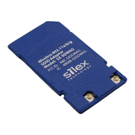
Chapter 1: Introduction The SX-SDWAG-02 is an 802.11a/b/g radio/baseband module in a standard SDIO form factor. 11a/b/g capabilities in an SDIO card form factor. Designed for wireless local area network (WLAN) applications that require low power consumption, the SX-SDWAG-02 is ideal for battery-operated portable devices in the medical, weights and measures, transportation and other industries. -
Page 7: Chapter 2 Hardware Specifications/Compliance
FCC ID: N6C-SXDWAG02 NOTICE In accordance with FCC Part 15, the SX-SDWAG-02 is listed as a Modular Transmitter device. End products that include the SX-SDWAG-02 shall have the words “Contains Transmitter module FCC ID: N6C- SXSDWAG02” on an exterior label. -
Page 8: Information For Canadian Users (Ic Notice)
while being used. Whereas high levels of RF can produce health effects (by heating tissue), exposure to low-level RF that does not produce heating effects causes no known adverse health effects. Many studies of low-level RF exposures have not found any biological effects. Some studies have suggested that some biological effects might occur, but such findings have not been confirmed by additional research. -
Page 9: Specifications
Specifications Temperature: 0º to +70ºC (+32º to +158ºF) Operating environment: Humidity: 10% to 90%RH Temperature: -40º to +85ºC (-40º to +185ºF) Storage environment: Humidity: 5% to 90% RH Supply voltage: +3.3V ± 0.3V SDIO v1.1 Host interface: Frequency bands and modulations: IEEE802.11b/g Frequency: 2412-2472MHz Channel: Ch.1-Ch.13... -
Page 10: Chapter 3 Installation
To install the SX-SDWAG-02: 1. Be sure to use the proper antistatic handling techniques. 2. Insert the SX-SDWAG-02 into an available SDIO slot in your device. Make sure that it is securely seated. 3. Connect one end of the antenna cable to the main antenna connector on the SX-SDWAG-02 (see figure 2). - Page 11 Figure 2 Connecting the Antenna Cable(s) to the SX-SDWAG-02 4. If your device is subject to significant vibration or other forces, silex recommends the use of a retaining bracket to prevent the accidental ejection of the card. This bracket can be the silex 150- 00192-100 retaining bracket (see figure 3) or an equivalent custom-made bracket.
-
Page 12: Appendix A Antenna Information
Appendix A Antenna Information Antenna Cable Drawings and Specifications Figure 2 Antenna Cable Assembly Antenna Information silex Page Revision A-1... -
Page 13: Antenna Drawings And Specifications
Table 1 Electrical Performance Parameter Value Impedance 50 ohms Frequency Range 1 to 6 GHz Working Voltage 500 VAC (rms) maximum Dielectric Withstanding Voltage 1000 VAC (rms) maximum Insulator Resistance 1000 megohms minimum Antenna Drawings and Specifications Figure 28 Antenna Mechanical Drawing Antenna Information silex Page 9... - Page 14 Table 2 Electrical Specifications Parameter Value Antenna Type Dipole Swivel Antenna Frequency Range 2.4 to 5.8 GHz Impedance 50 Ohms Gain 2.4 GHz < 1.5 dBi 5.825 GHz < 2.1 dBi ≤ 2.0 VSWR Admitted Power Radiation Omni Polarization Vertical Electrical Length ¼...
-
Page 15: Appendix B Silex Contact Information
Appendix B silex Contact Information Corporate Headquarters silex technology, Inc. www.silex.jp Tel: +81-6-6730-3751 Technical Support: support@silex.jp silex technology America, Inc. www.silexamerica.com Email: support@silexamerica.com Sales: sales@silexamerica.com Tel: (801) 748-1199 8:00 to 5:00 Mountain Time Tel: (866) 765-8761 toll-free Fax: (801) 748-0730 silex technology Europe GmbH www.silexeurope.com... - Page 16 Page 12 silex Contact Information Revision A-1...
- Page 17 Revision A-1...
- Page 18 silex technology, Inc. www.silex.jp Revision A-1...
Need help?
Do you have a question about the SX-SDWAG-02 and is the answer not in the manual?
Questions and answers