Table of Contents
Advertisement
Quick Links
This handbook includes the Maintenance Information and Illustrated Parts Catalog
for the GB1 GameBird required to be available by 14 CFR and CS-23.
Issued by Type Certificate Holder:
Game Composites LLC
3201 SW I Street, Bentonville, 72712 Arkansas, USA
FAA TCDS A00073CE
EASA TCDS A.610
www.gamecomposites.com
Maintenance Manual GB1 GameBird
Document No. AMM-GB1-0000-00-02
Issued to airplane S/N ________
Cover
Advertisement
Chapters
Table of Contents
Troubleshooting

Subscribe to Our Youtube Channel
Related Manuals for Game Composites GB1 GameBird

Summary of Contents for Game Composites GB1 GameBird
- Page 1 Maintenance Manual GB1 GameBird This handbook includes the Maintenance Information and Illustrated Parts Catalog for the GB1 GameBird required to be available by 14 CFR and CS-23. Document No. AMM-GB1-0000-00-02 Issued to airplane S/N ________ Issued by Type Certificate Holder:...
-
Page 2: List Of Revisions
40-12, GMU location 40-17, additional service step (Fire Sleeve) 51-13 Material Details added Obtaining Revisions Latest Revisions of Airplane Flight Manual & Supplements, Airplane Maintenance Manual and Service Bulletins are available on the Game Composites website: www.gamecomposites.com. Page date: April 24, 2020... -
Page 3: Table Of Contents
Maintenance Manual GB1 GameBird Table of Contents List of Revisions ............................... ii Obtaining Revisions ............................ii Table of Contents ............................iii Introduction ..............................iv Definition of Warnings, Cautions and Notes ....................v Units and Conversions ............................. v Glossary of Terms, Abbreviations and Symbols....................vi Description ........................... -
Page 4: Introduction
According to 14 CFR, this Maintenance Manual provides maintenance staff required information for the servicing, maintenance and repair of the GB1 GameBird. It includes: a detailed description of all systems including time limits for components, troubleshooting guidance; removal & installation procedures; inspection and maintenance instructions as well as repair instructions. -
Page 5: Definition Of Warnings, Cautions And Notes
Maintenance Manual GB1 GameBird Definition of Warnings, Cautions and Notes The following definitions apply: WARNING An operating procedure, inspection, repair or maintenance practice, which if not correctly followed, could result in personal injury, or loss of life. CAUTION An operating procedure, inspection, repair or maintenance practice, which, if not strictly observed, could result in damage or destruction of equipment. -
Page 6: Glossary Of Terms, Abbreviations And Symbols
Maintenance Manual GB1 GameBird Glossary of Terms, Abbreviations and Symbols Anti-Collision Lights Quantity Airworthiness Directive Revolutions per minute Airplane Flight Manual Secure Digital (Data Cards) Automatic Dependant Surveillance - Serial Number ADS-B Broadcast US Gallon (3.8 litres) AHRS Attitude Heading and Reference System... -
Page 7: Description
Maintenance Manual GB1 GameBird Description 01-01 Certification Category ........................1-2 01-02 Manufacturer ..........................1-2 01-03 Overview Drawing .......................... 1-3 01-04 Description ............................1-4 01-05 Equipment List ..........................1-5 Page date: April 24, 2020... -
Page 8: Certification Category
Maintenance Manual GB1 GameBird Certification Category The GB1 is a two-seat, high performance airplane certified in the aerobatic category in accordance with FAR 23, Amendment 64 and CS-23, Amendment 1. FAA TCDS A00073CE and EASA TCDS A.610. Certification is for day, VFR, non-icing conditions. -
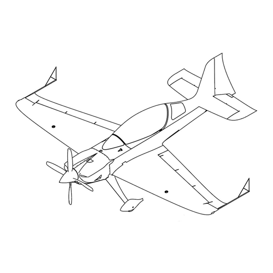
Page 9: Overview Drawing
Maintenance Manual GB1 GameBird Overview Drawing Page date: April 24, 2020... -
Page 10: Description
Maintenance Manual GB1 GameBird Description The GB1 is a conventional low wing monoplane with one front mounted reciprocating engine, driving a constant speed propeller. The cockpit features two seats in tandem arrangement, with the PIC in the rear. The landing gear is a fixed conventional tail-wheel arrangement. -
Page 11: Equipment List
Maintenance Manual GB1 GameBird Equipment List The GB1 is certified to operate in day VFR only, for which the following systems and items of equipment must be installed and operational to perform their intended function: Standard / Rear Front Optional /... -
Page 12: Airworthiness Limitations
Maintenance Manual GB1 GameBird Airworthiness Limitations 4-01 General ............................4-2 4-02 Operating Time ..........................4-2 4-03 Life Limited Parts ..........................4-2 4-04 Structure Temperature Limitation ....................4-2 Page date: April 24, 2020... - Page 13 Maintenance Manual GB1 GameBird General This Airworthiness Limitations Section is EASA approved. It specifies inspection and maintenance required according to CS-23 Appendix G, 23.4 unless an alternative program has been EASA approved. This Airworthiness Limitations Section is FAA approved and specifies maintenance required under 14 CFR §§...
-
Page 14: Time Limits, Access, Maintenance Checks
Maintenance Manual GB1 GameBird Time Limits, Access, Maintenance Checks General ............................5-2 Time Limits ........................... 5-2 Recommended Replacement Times .................... 5-2 Introduction ..........................5-3 Access ............................5-4 Component Inspections ....................... 5-5 25-Hour Inspection Checklist ....................... 5-7 50-Hour Inspection Checklist ....................... 5-8 100-Hour Inspection Checklist .................... -
Page 15: General
It is recommended to check for the latest revision of each referenced document before conducting maintenance. Additional information may be given by Game Composites through service bulletins and service letters on the company web site and by circulation to known operators. The operator must ensure that all airworthiness directives, service bulletins and any other requirements of the airworthiness authority are completed as required. -
Page 16: Introduction
Maintenance Manual GB1 GameBird Introduction An airworthiness authority may issue Airworthiness Directives, requiring inspections additional to those defined in this manual. The operator is responsible for compliance with all applicable ADs and periodic inspections. Pilots operating the airplane should refer to the regulations of the country of registration for information concerning what maintenance may be performed by pilots. -
Page 17: Access
Maintenance Manual GB1 GameBird Access For inspection, the following panels may be removed or opened as appropriate. Items that have their own chapter in this Manual (for example cowling) are not listed here. The inspection checklists assume that this has been done and does not repeat the instruction to remove and reinstall these panels. -
Page 18: Component Inspections
Maintenance Manual GB1 GameBird Component Inspections Items Inspection points Inspection Criteria Criteria for replacement Inspection Type Standard Fasteners Surface, Coating worn, chafed visible dents, permanent deformation Thread clean abrasion beyond chafing of coating, damaged thread visual Head Tool fit permanent deformation, beyond chafing... - Page 19 Maintenance Manual GB1 GameBird Items Inspection points Inspection Criteria Criteria for replacement Inspection Type Canopy retaining strap surface and weave fraying, bleaching from UV, wear of visible frays, visible bleaching / brittleness, wear / visual attachment area elongation around attachment...
-
Page 20: 25-Hour Inspection Checklist
Maintenance Manual GB1 GameBird For inspection criteria, refer to 5-06 Component Inspection Table. For detailed descriptions, refer to the relevant chapters of this Manual. Depending on country of registration, an appropriate maintenance entry in the aircraft maintenance records might be required, or the relevant pages of this manual may be printed and signed. -
Page 21: 50-Hour Inspection Checklist
Maintenance Manual GB1 GameBird 50-Hour Inspection Checklist Item Reference Initials Engine Ground run in accordance with AFM section 4.4, 4.6, 4.11, up to 200°F oil Temperature Remove cowling 71-02 Visually check oil cooler and lines installation for leaks or chafing... - Page 22 Maintenance Manual GB1 GameBird Reference Item Initials Canopy Lock function and visually check condition of parts and fasteners 52-05 Visually check canopy glass condition 52-01 Check freedom of movement, opening and closing canopy Visually check retaining strap installation and condition...
- Page 23 Maintenance Manual GB1 GameBird Reference Item Initials 5-06 Visually check overall condition 27-16 27-16 Check rudder cable tension 10-12 lbs, adjust if needed 27-16 Error! R Visually check safety wires in rudder cable turnbuckle (in tail wheel fairing) 27-26 eference...
- Page 24 Maintenance Manual GB1 GameBird Reference Item Initials Avionics master switch-breaker OFF 39-01 Master Switch OFF 39-01 Pitot / Static System Visually check attachment of pitot tube to wing and static tube to static ports 31-02 on fuselage, condition of assembly...
- Page 25 Maintenance Manual GB1 GameBird Reference Item Initials Seat belts, front and rear cockpits 25-12 Visually check installation and overall condition of shoulder belts Visually check installation, overall condition and gap (see) of Load Limiters 25-12 Visually check installation and general condition of lap belts...
-
Page 26: 100-Hour Inspection Checklist
Maintenance Manual GB1 GameBird 100-Hour Inspection Checklist Repeat 25- and 50-hour inspections. In addition, complete the following items: Item Reference Initial Check metal firewall and surrounding composite structure for damage and 5-06 cracks 51-01 Visual check of composite structure all over, including behind inspection... -
Page 27: 1000-Hour Inspection Checklist
Maintenance Manual GB1 GameBird 1000-Hour Inspection Checklist Disassemble the airplane and perform a detailed inspection of all components. In particular, perform non-destructive Inspection of all composite structure bond lines. Item Reference Initial Remove, clean, disassemble and check tail-wheel assembly 32-05... -
Page 28: Inspection Log
Maintenance Manual GB1 GameBird Inspection Log Flight Name of Name of Date Initials Hours Approved Maintenance Organization Certifying Inspector 1000 5-15 Page date: April 24, 2020... -
Page 29: In-Flight Overload
Maintenance Manual GB1 GameBird In-flight Overload If one of the accelerometers indicates more than the approved loads, contact Game Composites. Impacts, Flight or Ground including Bird Strike Item Initial Check upper and exposed areas by visual inspection for unevenness, cracks, delamination or any other evidence of for structural damage per 51-01. -
Page 30: Engine Bay Fire
Maintenance Manual GB1 GameBird Engine Bay Fire Item Initial Visually check cowling for structural damage (51-01) Visually check fuel and oil lines for discoloring or damage Visually check wiring (51-01) Visually check control cables for damage, check for function Lightning Strike... -
Page 31: Dimensions And Rigging Information
Maintenance Manual GB1 GameBird Dimensions and Rigging Information For Rigging Information see section For Overview Drawing see section 1-03. Page date: April 24, 2020... -
Page 32: Lifting And Supporting
Maintenance Manual GB1 GameBird Lifting and Supporting 7-01 Lifting .............................. 7-2 7-02 Supporting ............................7-2 Page date: April 24, 2020... - Page 33 Maintenance Manual GB1 GameBird Lifting The engine case features two engine hoist lugs, which are accessible with the cowlings removed (see section 71-02), those be used to lift the airplane with a crane (tail-wheel resting on ground). When a wheel needs to be changed and no hoist is available, one wing tip can be lifted manually.
-
Page 34: Levelling And Weighing
Maintenance Manual GB1 GameBird Levelling and Weighing Establish Empty Weight & Centre of Gravity .................. 8-2 Moment Arms ..........................8-2 Page date: April 24, 2020... - Page 35 Maintenance Manual GB1 GameBird Establish Empty Weight & Centre of Gravity 1. Drain all fuel tanks to unusable fuel level (see 12-06) 2. Empty the smoke oil tanks (see 12-06) 3. Remove optional tail ballast (see 41-02) 4. Ensure engine oil and brake fluid levels are correct 5.
- Page 36 Maintenance Manual GB1 GameBird Moment Arms Limitation Item Weight Moment Kg/m Lb/in Empty weight 0.53 20.9 Weight × Arm Front seat 1.16 45.6 Weight × Arm Rear seat 2.16 Weight × Arm Fuel, Acrotank 0.26 10.2 Weight × Arm Fuel, left Wing 0.33...
-
Page 37: Moving And Towing
Maintenance Manual GB1 GameBird Moving and Towing With its low weight and the free swiveling tail wheel, two people can easily move the GB1 by hand. The best area to push is the leading edge of the wings, while the best place to pull is the propeller, close to the roots of the blades. -
Page 38: Parking, Mooring, Storage & Return To Service
Maintenance Manual GB1 GameBird Parking, Mooring, Storage & Return to Service Short Term Parking ........................10-2 Long term storage ......................... 10-2 10-1 Page date: April 24, 2020... - Page 39 Maintenance Manual GB1 GameBird Short Term Parking • If the airplane is parked in the open, secure the wheels with chocks. • When windy, tie down the airplane using ropes around the tail wheel and at the outer aileron hinges •...
-
Page 40: Placards
Maintenance Manual GB1 GameBird Placards General ............................11-2 Exterior Color Schemes and Markings ..................11-2 Exterior Placards ........................... 11-2 Interior Placards ..........................11-5 11-1 Page date: April 24, 2020... - Page 41 Maintenance Manual GB1 GameBird General Placards show the function, operation and operating limitations of systems and equipment. Placards are required and defined by the design regulations. They must not be removed, exchanged or altered unless approved by the airworthiness authority or Approved Design Organization.
- Page 42 Maintenance Manual GB1 GameBird GB1-1120-00-05 Oil Filler GB1-1120-00-06 Smoke Oil Filler GB1-1120-00-07 Wing Tank Drain GB1-1120-00-08 Wing Tank Vent GB1-1120-00-10 Acrotank Filler 11-3 Page date: April 24, 2020...
- Page 43 Maintenance Manual GB1 GameBird GB1-1120-00-11 Wing Tank Filler GB1-1120-00-16 Tire Pressure GB1-1120-00-17 Oil Breather GB1-1120-00-18 Ballast Weight 13.5kg GB1-1120-00-20 Gascolator Drain GB1-1120-00-21 External Power 11-4 Page date: April 24, 2020...
- Page 44 Maintenance Manual GB1 GameBird Interior Placards Item No. Part Number Description Quantity GB1-1130-00-05 Placard, Canopy Lock GB1-1130-00-06 Placard, Baggage Compartment GB1-1130-00-08 Placard, Headset Sockets GB1-1130-00-14 Placard, V GB1-1130-00-16 Placard, Wing Tank Empty GB1-1130-00-20 Placard, Baggage Lock GB1-1130-00-23 Placard, Aerobatics GB1-1130-00-24...
- Page 45 Maintenance Manual GB1 GameBird GB1-1130-00-05 Canopy Lock GB1-1130-00-06 Baggage Compartment GB1-1130-00-08 Head Set Socket GB1-1130-00-14 GB1-1130-00-16 Fuel Management GB1-1130-00-20 Baggage Door GB1-1130-00-23 Aerobatic Placard Compass Deviation Card Recognition Lights 11-6 Page date: April 24, 2020...
-
Page 46: Tools, Servicing, Cleaning
Maintenance Manual GB1 GameBird Tools, Servicing, Cleaning General ............................12-2 Airframe Tools ........................... 12-2 Metric fasteners ......................... 12-3 Fuel Drain Checks ........................12-3 Refueling ............................ 12-3 Defueling ............................ 12-3 Engine Oil Level Check and Top-up .................... 12-3 Engine Oil Change Service......................12-4 Tires and Tire Pressures ...................... - Page 47 Maintenance Manual GB1 GameBird General This chapter gives information about the servicing of the airplane. It is recommended to consider shortening service and maintenance intervals when operating under abnormal conditions, such as: • Extreme temperature ranges • Dusty atmospheric conditions •...
- Page 48 Maintenance Manual GB1 GameBird Metric fasteners Metric fasteners are used in the following components: • M3 to secure the grips on the control sticks and the throttle, propeller & mixture controls • M5 to attach the control system elastomeric bump stops •...
- Page 49 Maintenance Manual GB1 GameBird Engine Oil Change Service See section 12-07 for oil specifications. As defined in 5-08, the engine oil change service interval is 25 flight hours. To conduct an oil change: 1 Ground run in accordance with AFM section 4.4, 4.6, 4.11, up to 200°F oil Temperature...
- Page 50 Use a leather to dry the surfaces. The painted surfaces can be treated with a non-silicone car polish and re-polished to high gloss. Game Composites recommends polishing the entire airplane twice a year. Cleaning, canopy and windshield Material for canopy and windshield is Plexiglas To clean the canopy, use only clean water or products approved for use on Plexiglass, and clean chamois / micro fiber cloth only used for canopy cleaning.
-
Page 51: Standard Practices And Shipping
Maintenance Manual GB1 GameBird Standard Practices and Shipping General ............................20-2 Threaded Fasteners & Torque Values ..................20-2 Spherical Bearings ........................20-3 Adhesive Nutplates ........................20-3 Adhesives and Sealants......................20-4 Flexible Hoses and Hose Fittings ....................20-5 Disassembly for Shipping ......................20-5 Crating for shipping ........................ -
Page 52: General
Maintenance Manual GB1 GameBird General This chapter contains torque values, description of standard components, fasteners and sealants, as well as instructions for disassembly, shipping and reassembly of the airplane. Threaded Fasteners & Torque Values Always tighten the nut or bolt to the torque shown below unless otherwise stated. -
Page 53: Spherical Bearings
Bearings that have been removed using this method have to be replaced! CAUTION: Make sure that surrounding composite structure does not overheat, no discernible smell / smoke! In case of overheating, contact Game Composites! Installation of bearings: 1. Remove all residue of old Threadlock 2. De-grease surface with solvent 3. -
Page 54: Adhesives And Sealants
Maintenance Manual GB1 GameBird Adhesives and Sealants Tank Sealant PPG P/S 890 Class B P/S 890 Class B is an aircraft integral fuel tank sealant, supplied in two-part kits and Semco® cartridges. It is used to seal access panels of the Wing- and Acrotank, as well as seal and threadlock bulkhead fittings. -
Page 55: Flexible Hoses And Hose Fittings
Maintenance Manual GB1 GameBird Flexible Hoses and Hose Fittings Maintenance or overhaul work of the flexible hoses should be performed in accordance with the hose manufacturer’s service information and service bulletins. Hoses and hose assemblies should be visually checked during each inspection. -
Page 56: Crating For Shipping
Maintenance Manual GB1 GameBird Crating for shipping Wing support box drawing: Outer wing support: Print this page and use outline as a template. Material should be foam of density no less than 20kg/m Width no less than 100 mm / 4in. - Page 57 Maintenance Manual GB1 GameBird Crating arrangement shown for standard M-6 airfreight pallet All ratchet straps must be rated 500kg / 1000lbs or higher. 1. Lift wings in position per drawing 2. Reinstall or securely wrap and tie down in cockpit (using seat belts) loose items 3.
- Page 58 Maintenance Manual GB1 GameBird 20-8 Page date: April 24, 2020...
-
Page 59: Reassembly After Shipping
On receipt, carefully check if airplane or components have moved, shifted of chafed during the transport. Visually inspect all exterior surfaces, and check Shock Watch indicator. If 8G are exceeded, or if evidence of larger loads exists, contact Game Composites. Step... -
Page 60: Air Conditioning
Maintenance Manual GB1 GameBird Air Conditioning Each of the four fresh air vents for the occupants receives air from its adjacent air inlet. 2 manually adjustable eyeball air vents are located right and left of each instrument panel. No regular maintenance is required for the unit. -
Page 61: Communication
Maintenance Manual GB1 GameBird Communication General ............................23-2 VHF Radio............................23-2 VHF Antenna ..........................23-4 MIC / PHONE Jacks........................23-5 VHF Check ............................. 23-5 23-1 Page date: April 24, 2020... - Page 62 Maintenance Manual GB1 GameBird General This chapter describes systems, units and components which provide means of internal and external communication within, and between airplanes and ground stations. VHF Radio The speech communication consists of one digitally-tuned integrated VHF communication (COM) transceiver.
- Page 63 Maintenance Manual GB1 GameBird Creating a GTR/GNC Software Loader USB Flash Drive 1. Go to https://dealers.garmin.com/drc/login 2. Download the applicable GTR/GNC software to your PC. 3. Ensure the flash drive is inserted into the USB slot of the PC. 4. Run the downloaded executable file and follow the prompts to create the software loader USB drive.
- Page 64 Maintenance Manual GB1 GameBird No regular maintenance is required for the unit. For troubleshooting or additional information, refer to: Garmin GTR 225/GNC 255 TSO Installation Manual, 190-01182-02, Revision G. For wiring and connection details, refer to section 24-03. To uninstall the VHF for service: 1.
- Page 65 Stereo Headphone Jacks: Switchcraft, 3-Circuit SWC-12B Microphone Jack: Switchcraft, 3-Circuit SWC-12B-JJ-033 Each Jack is mounted with included hardware in an insulator plate Cliff CL1396 Those components are available through Game Composites, or various other vendors. For wiring and connection details, refer to section 24-03...
-
Page 66: Electric Power Including Switches & Breakers
Maintenance Manual GB1 GameBird Electric Power including Switches & Breakers Electrical System, General ......................24-2 Electrical Distribution, Switches and Circuit Breakers ............... 24-4 Wiring loom ..........................24-5 Alternator ..........................24-20 Battery ............................. 24-21 Voltage Regulator ........................24-22 Master Relay ..........................24-23 Starter Relay .......................... -
Page 67: Electrical System, General
Maintenance Manual GB1 GameBird Electrical System, General This chapter contains information on DC Generation and Electrical Load Distribution. The airplane is equipped with a 14-volt direct current (VDC) electrical system. The system provides uninterrupted power for avionics, flight instrumentation, lighting, trim system and other electrical devices during normal operation. - Page 68 Maintenance Manual GB1 GameBird The Avionic CB Switch is energized via the Master Relay, directing power to: VHF, via the VHF CB Transponder, via the XPDR CB MFD2, via the MFD2 CB ADHRS, via AHRS CB Landing Lights, via Landing Lights CB Switch, located on LH side console in the rear cockpit.
-
Page 69: Electrical Distribution, Switches And Circuit Breakers
Maintenance Manual GB1 GameBird Electrical Distribution, Switches and Circuit Breakers Electrical supply from alternator and battery is distributed via switches and circuit-breakers. All cables are 55A0811 series with PVC –jacket Alpha Wire 1716Sl005 Unless noted otherwise, the controls are in the rear right-hand side console. -
Page 70: Wiring Loom
Maintenance Manual GB1 GameBird Wiring loom 24-5 Page date: April 24, 2020... - Page 71 Maintenance Manual GB1 GameBird 24-6 Page date: April 24, 2020...
- Page 72 Maintenance Manual GB1 GameBird 24-7 Page date: April 24, 2020...
- Page 73 Maintenance Manual GB1 GameBird 24-8 Page date: April 24, 2020...
- Page 74 Maintenance Manual GB1 GameBird 24-9 Page date: April 24, 2020...
- Page 75 Maintenance Manual GB1 GameBird 24-10 Page date: April 24, 2020...
- Page 76 Maintenance Manual GB1 GameBird 24-11 Page date: April 24, 2020...
- Page 77 Maintenance Manual GB1 GameBird 24-12 Page date: April 24, 2020...
- Page 78 Maintenance Manual GB1 GameBird 24-13 Page date: April 24, 2020...
- Page 79 Maintenance Manual GB1 GameBird 24-14 Page date: April 24, 2020...
- Page 80 Maintenance Manual GB1 GameBird 24-15 Page date: April 24, 2020...
- Page 81 Maintenance Manual GB1 GameBird 24-16 Page date: April 24, 2020...
- Page 82 Maintenance Manual GB1 GameBird 24-17 Page date: April 24, 2020...
- Page 83 Maintenance Manual GB1 GameBird 24-18 Page date: April 24, 2020...
- Page 84 Maintenance Manual GB1 GameBird 24-19 Page date: April 24, 2020...
-
Page 85: Alternator
Maintenance Manual GB1 GameBird Alternator Location: Engine backside, upper accessory pad Type: BC-410-H gear driven DC alternator Accessories: B&C adaptor plate VAC-2/6 and B&C gear shaft 72974 Manufacturer: B&C Specialty Products 123 E. 4th Street POB B, Newton, KS 67114, USA www.bandc.aero... -
Page 86: Battery
Maintenance Manual GB1 GameBird Battery Type: Odyssey Extreme PC535 Manufacturer: EnerSys Inc. 2366 Bernville Road, Reading, PA 19605, USA www.odysseybattery.com No regular maintenance is required for the unit. The battery is located in the left front footwell. The battery can be charged while installed. -
Page 87: Voltage Regulator
Maintenance Manual GB1 GameBird Voltage Regulator Location: Compartment under the left front leg support, root rib Type: LR3C-14 Regulator Manufacturer: B&C Specialty Products 123 E. 4th Street POB B, Newton, KS 67114, USA www.bandc.aero No regular maintenance is required for the unit. -
Page 88: Master Relay
Maintenance Manual GB1 GameBird Master Relay Location: Compartment under the left front leg support, tank support wall, behind Starter Relay Type: 70-111226-6 Manufacturer: White-Rodgers 8100 West Florissant, PO Box 36922, St. Louis, MO 63136-9022, USA www.emersonclimate.com No regular maintenance is required for the unit. When defective, unit must be replaced. -
Page 89: External Power Socket
Maintenance Manual GB1 GameBird External Power Socket The GB1 is equipped with a Piper-Style external power socket, allowing the use of an external power source. Wiring requires the Battery Master Switch to be ON to apply external power. The power source must be regulated to 12V DC. -
Page 90: Electrical System Inspection Guide
Maintenance Manual GB1 GameBird Electrical System Inspection Guide Wires / wiring harness 1. Check for broken, disconnected or corroded bonding strap and grounding 2. Check for Improper, broken, inadequately supported wiring and conduit and loose connections of terminals. Check conditions of clamps, plastic cable ties and rubber grommets. Clamp retaining screws should be properly secured. - Page 91 Maintenance Manual GB1 GameBird 24-26 Page date: April 24, 2020...
-
Page 92: Connectors, Terminals And Splices
Maintenance Manual GB1 GameBird Choose shielded wires from the table below: Connectors, terminals and splices 1. Check condition of connectors for security and sign of overheating, causing poor connection between wire(s) and pin(s). 2. Ensure all connectors are fully mated. -
Page 93: Terminal Blocks And Studs
Maintenance Manual GB1 GameBird Terminal blocks and studs 1. Check bus terminal blocks and studs for general condition and security of all attachments and terminals. Terminal blocks that exhibit corrosion, even in limited amounts, should be disassembled and cleaned before reinstallation. Bigfoot studs cannot be removed. -
Page 94: Voltage Regulator
Maintenance Manual GB1 GameBird Voltage Regulator When battery is not charged during normal operation or in case of abnormally high or low charging current: 1. Turn on master switch BAT and ALT, and circuit breaker Field. Measure voltage on battery bus and on pin 6 of the regulator. -
Page 95: Boost Pump
Maintenance Manual GB1 GameBird Boost Pump When the pump does not prime: 1. Turn ON BAT master switch. Turn on toggle switch Boost Pump and measure voltage on the power cables of the pump. A voltage not lower than 11V is required for the pump to work. -
Page 96: Equipment And Furnishings
Maintenance Manual GB1 GameBird Equipment and Furnishings 25-01 Cleaning ............................. 25-2 25-02 Seat Cushion, rear seat – GB1-2520-01-00 ................25-2 25-03 Seat Cushion, front seat – GB1-2520-02-00 ................25-2 25-04 Side pocket rear seat, left-hand – GB1-2520-13-00 ..............25-2 25-05 Side pocket rear seat, right-hand - GB1-2520-14-00 .............. - Page 97 This seat cushion is part of the occupant protection system and may not be changed or modified. It is fixed to the seat with Velcro and can be removed for cleaning. For repair instructions, contact Game Composites. Seat Cushion, front seat – GB1-2520-02-00 This seat cushion is part of the occupant protection system and may not be changed or modified.
- Page 98 Maintenance Manual GB1 GameBird Seat belts – GB1-2500-10-00 Manufacturer Hooker Custom Harness, Inc. 324 East Stephenson St Freeport, Illinois 61032, USA www.hookerharness.com The Equipment Manufacturer recommends replacement / repair of harness systems based upon condition not physical age. Some governing agencies require replacement based upon age regardless of condition (10 years is common).
- Page 99 Maintenance Manual GB1 GameBird 3. Stitching: A. Broken or missing stitches B. Severe fading or discoloration. (see 1B above) C. Inconsistent pattern or thread size. Structural thread size should be the same throughout the entire harness. Irregular patterns or varied sizes may be indicative of field modification.
- Page 100 Maintenance Manual GB1 GameBird Load Limiters (integrated into front and rear shoulder belts) 1. Open / remove padding 2. Remove pins 3. Take out Load Limiter, check for overall condition 4. check gap 6 mm, ± 2 mm; When gap is out of tolerance, replace part.
-
Page 101: Flight Controls
Maintenance Manual GB1 GameBird Flight Controls Description ............................ 27-2 Elevator and aileron control system ..................... 27-3 Front Control Stick - GB1-2703-10-00 ................... 27-4 Aft Control Stick - GB1-2703-11-00 ....................27-5 Torque Tube - GB1-2717-11-00 ....................27-6 Torque tube front bearing - GB1-2717-10-01 ................27-7 Torque tube aft bearing –... -
Page 102: Description
Maintenance Manual GB1 GameBird Description This chapter describes the design, operation and adjustment of the flight control system assemblies. Refer to the relevant sub-chapters for specific information about each system. The airplane has conventional mechanical stick and rudder flight control systems. -
Page 103: Elevator And Aileron Control System
Maintenance Manual GB1 GameBird Elevator and aileron control system GB1-2703-10-00 Front Control Stick GB1-2703-11-00 Aft Control Stick GB1-2717-23-00 Aileron Control Rod (Torque Tube to Bellcrank) GB1-2717-11-00 Torque Tube GB1-2717-30-00 Aileron Bellcrank GB1-2717-40-00 Aileron Control Rod (Bellcrank to Aileron GB1-2733-20-00 Elevator Control Rod (Torque Tube to Idler) -
Page 104: Front Control Stick - Gb1-2703-10-00
Maintenance Manual GB1 GameBird Front Control Stick - GB1-2703-10-00 The front control stick is a welded assembly, powder coated for protection, with wooden stick grip halves mounted by M3 fasteners and the PTT momentary switch installed in the top face plate; electric connection from PTT to the VHF is routed through the main tube. -
Page 105: Aft Control Stick - Gb1-2703-11-00
Maintenance Manual GB1 GameBird Aft Control Stick - GB1-2703-11-00 The aft control stick is a welded assembly, powder coated for protection, with wooden stick grip halves mounted by M3 fasteners and the PTT momentary switch installed in the top face plate; electric connection from PTT to the VHF is routed through the main tube. -
Page 106: Torque Tube - Gb1-2717-11-00
Maintenance Manual GB1 GameBird Torque Tube - GB1-2717-11-00 In the rear cockpit 1. Remove the stick as described in section 27-04 2. Remove the radio and transponder 3. Remove the upper bearing cap (four bolts) 4. Disconnect the elevator rod In the front cockpit 1. -
Page 107: Torque Tube Front Bearing - Gb1-2717-10-01
Maintenance Manual GB1 GameBird Torque tube front bearing - GB1-2717-10-01 To service the front torque tube bearing, the following items have to be removed: 1. Front seat cushion and panel (4 screws) 2. Wings per section 20-07 In the spar carry-through box: 3. -
Page 108: Torque Tube Aft Bearing - Gb1-2717-10-05
Maintenance Manual GB1 GameBird Torque tube aft bearing – GB1-2717-10-05 The aft torque tube bearing consists of the following parts: 1. Bottom bearing housing, composite part bonded between the seat support bulkheads 2. Bearing housing, GB1-2717-10-05 3. Split bushing GB1-2717-10-91 The split bushing is defining the play / breakout torque of the torque tube assembly. -
Page 109: Aileron Control Rods, Torque Tube To Bellcrank - Gb1-2717-21-00
Maintenance Manual GB1 GameBird Aileron control rods, torque tube to bellcrank - GB1-2717-21-00 Proceed as follows to inspect or service: In the front cockpit 1. Disconnect the aileron rods from the torque tube 2. Remove wing Underside of the relevant wing 3. -
Page 110: Aileron Control Rods, Bellcrank To Aileron - Gb1-2717-40-00
Maintenance Manual GB1 GameBird Aileron control rods, bellcrank to aileron - GB1-2717-40-00 Proceed as follows to inspect or service: Under the relevant wing: 1. Remove the bellcrank access panel (3 screws each panel) 2. Disconnect the rod from the bellcrank and aileron arms 3. -
Page 111: Aileron Bellcrank And Bearings - Gb1-2717-30-00
Maintenance Manual GB1 GameBird Aileron Bellcrank and Bearings – GB1-2717-30-00 Proceed as follows to inspect or service: 1. Remove the underwing access panel 2. Disconnect both aileron rods from the bellcrank 3. Remove both pivot bolts and maneuver the bellcrank out of the wing 4. -
Page 112: Elevator Control Rod, Inside Torque Tube - Gb1-2733-10-00
Maintenance Manual GB1 GameBird Elevator control rod, inside torque tube - GB1-2733-10-00 Proceed as follows to inspect or service: 1. Remove aft control stick 2. Disconnect elevator rod from front control stick 3. Pull elevator rod out towards the rear 4. -
Page 113: Elevator Control Rod, Torque Tube To Elevator Idler - Gb1-2733-20-00
Maintenance Manual GB1 GameBird Elevator control rod, Torque Tube to Elevator Idler - GB1-2733-20-00 Proceed as follows to inspect or service: 1. Remove the rear seat cushion and panel (4 screws) 2. Disconnect the elevator rod from the stick and the idler then lift it out 3. -
Page 114: Elevator Control Rod, Idler To Elevator Bellcrank - Gb1-2733-40-00
Maintenance Manual GB1 GameBird Elevator control rod, idler to Elevator Bellcrank - GB1-2733-40-00 Proceed as follows to inspect or service: 1. Remove the rear seat cushion and panel (4 screws) 2. Disconnect the elevator rod from the idler 3. Remove the rudder as described below 4. -
Page 115: Elevator Idler - Gb1-2733-30-00
Maintenance Manual GB1 GameBird Elevator Idler - GB1-2733-30-00 Proceed as follows to inspect or service: 1. Remove the rear seat cushion and panel (4 screws) 2. Remove baggage floor inspection panel 3. Disconnect both elevator rods from the Elevator Idler 4. -
Page 116: Elevator Bellcrank - Gb1-2733-50-00
Maintenance Manual GB1 GameBird Elevator Bellcrank – GB1-2733-50-00 Proceed as follows to inspect or service: 1. Remove rudder 2. Remove elevators 3. Disconnect elevator push rod 4. Remove both vertical fasteners 5. Slide outboard parts out 6. Remove center section 7. -
Page 117: Rudder Control System - Gb1-2723-00-00
Maintenance Manual GB1 GameBird Rudder control system – GB1-2723-00-00 GB1-2723-11-00 Rudder Pedal Front LH GB1-2723-12-00 Rudder Pedal Front RH GB1-2723-13-00 Rudder Pedal Aft LH GB1-2723-14-00 Rudder Pedal Aft RH GB1-2723-21-00 Rudder Pedal Adjuster, front GB1-2723-25-00 Rudder Pedal Adjuster, aft GB1-2723-31-00... -
Page 118: Rudder Pedal Assembly, Front Seat - Gb1-2722-00-00
Maintenance Manual GB1 GameBird Rudder pedal assembly, front seat – GB1-2722-00-00 Front seat, LH pedal assembly Allowable play of slider on rails: No more than 4 mm vertical movement of pedal assembly, measured with a ruler between cockpit floor and lowest point of rudder pedal. - Page 119 Maintenance Manual GB1 GameBird To service either front rudder pedal assembly: Remove brake line, catch spilled brake fluid, cap off brake lines Remove disconnect pedal adjuster Pull back until free of rails, remove assembly from airplane Clean all components Inspect standard fasteners in accordance with 5-06, No.1 Inspect slider in accordance with 5-06, No.6...
-
Page 120: Rudder Pedal Adjusters, Front Seat - Gb1-2723-21-00
Maintenance Manual GB1 GameBird Rudder pedal adjusters, front seat – GB1-2723-21-00 Proceed as follows to inspect or service: 1. Remove front instrument panel 2. Disconnect fasteners on both ends 3. Remove from airplane 4. Remove spring loaded locating pin 5. Slide components apart 6. -
Page 121: Rudder Interconnecting Rod, Front Right - Gb1-2723-42-00
Maintenance Manual GB1 GameBird Rudder interconnecting rod, front right – GB1-2723-42-00 To service: 1. Remove front instrument panel 2. Remove front seat 3. Remove fasteners on both ends 4. Remove interconnecting rod 5. Remove bellcrank 6. Clean all components 7. Inspect standard fasteners in accordance with 5-06, No.1 8. -
Page 122: Rudder Bellcrank Mount, Center - Gb1-2723-50-00
Maintenance Manual GB1 GameBird Rudder bellcrank mount, center – GB1-2723-50-00 To service center rudder bellcrank mount: 1. Remove front seat 2. Remove pivot fasteners of center rudder bellcrank 3. Remove locating fasteners 4. Remove bellcrank 5. Clean all components 6. Inspect standard fasteners in accordance with 5-06, No.1 7. -
Page 123: Rudder Bellcranks, Center - Gb1-2723-61-00
Maintenance Manual GB1 GameBird Rudder bellcranks, center – GB1-2723-61-00 To service either center rudder bellcrank: 1. Remove front seat 2. Disconnect from interconnecting rods 3. Remove pivot fastener 4. Remove bellcrank from airplane 5. Clean assembly 6. Remove bellcrank 7. Clean all components 8. -
Page 124: Rudder Interconnecting Rods, Rear Right - Gb1-2723-44-00
Maintenance Manual GB1 GameBird Rudder interconnecting rods, rear right – GB1-2723-44-00 To service right rudder interconnecting rod: 1. Remove front and rear seat cushions and panels (6 screws front, 4 screws rear) 2. Remove fasteners on both ends 3. Remove interconnecting rod 4. -
Page 125: Rudder Bellcrank Assembly, Aft
Maintenance Manual GB1 GameBird Rudder bellcrank assembly, aft 27-26 To service aft rudder bellcrank-GB1-2723-81-00: 1. Remove rear seat cushion and panel (4 screws) 2. Disconnect interconnecting rods to front pedals 3. Remove pivot fastener 4. Slide either side, disconnect rudder cables and rear pedal adjusters 5. -
Page 126: Rudder Control Mount
Maintenance Manual GB1 GameBird Rudder Control Mount To service aft rudder bellcrank mount-GB1-2723-70-00: 1. Remove rear seat cushion and panel (4 screws) 2. Remove aft rudder bellcrank 3. Remove locating fasteners 4. slide forward, remove from airplane 5. Remove bellcrank 6. -
Page 127: Rudder Pedal Assembly, Rear Seat
Maintenance Manual GB1 GameBird Rudder pedal assembly, rear seat Part No. Description 07534-06X 20 mm M5 shoulder screw Wsh_M6_Pln_Ss M6 plain washer ISO 7089 stainless Nut_M5_Nyloc Nut, M5, Nyloc, DIN985_A2 NAS1351-3-6P Screw Cap Skt Hd 10-32 UNF x 0.375 CPS... - Page 128 Maintenance Manual GB1 GameBird To service either rear pedal assembly: 1. Remove brake line, catch spilled brake fluid, cap off brake lines 2. Remove disconnect pedal adjuster 3. Remove upper rollers 4. Remove assembly from airplane 5. Clean all components 6.
-
Page 129: Rudder Pedal Adjusters, Rear Seat - Gb1-2723-25-00
Maintenance Manual GB1 GameBird Rudder pedal adjusters, rear seat – GB1-2723-25-00 To service either rear seat pedal adjuster: 1. Remove rear seat cushion and panel (4 screws) 2. Remove pivot fastener of aft bellcrank 3. Disconnect fasteners on both ends 4. -
Page 130: Rudder Cable, Rh - Gb1-2723-80-91
Maintenance Manual GB1 GameBird Rudder Cable, RH – GB1-2723-80-91 Turn counter-clockwise to reduce tension To service the RH rudder cable: 1. Remove rear seat cushion and panel, refer to section 5-05 2. Disconnect the cable from the center bellcrank 3. Remove tail fairing 4. -
Page 131: Rudder Cable, Lh - Gb1-2723-80-92
Rudder Rig Jig JIG-GB1-2723-80-00 2 Jigs are required to conduct the rudder cable rigging procedure described in section 5-05. Jigs can be ordered from Game Composites, or fabricated from 19mm / ¾” plywood or MDF, To drawing as shown. Dimensions: Length A: 210mm, ±2mm / 8.26”, ±0.1”... -
Page 132: Rudder Bellcrank - Gb1-2723-90-00
Maintenance Manual GB1 GameBird Rudder Bellcrank – GB1-2723-90-00 To service the rudder bellcrank: Remove Rudder Remove fasteners Remove bellcrank from Rudder Clean all components Inspect standard fasteners in accordance with 5-06, No.1 Inspect spherical bearings in accordance with 5-06, No.14 To reinstall, reverse steps 1 –... -
Page 133: Uninstall Front Seat Flight Controls
Maintenance Manual GB1 GameBird Uninstall Front Seat Flight Controls The front seat flight controls can be uninstalled to conduct flights with passengers, or reduce weight for competition flying. The dual-control configuration can be restored with reference to section 27-80. 27-33... - Page 134 Maintenance Manual GB1 GameBird Uninstall front control stick 1. Remove both seat cushions and seat panels (6 screws front panel, 4 screws rear) 2. Remove baggage bay access panel 3. Disconnect front control stick PTT connector 4. Remove fasteners, remove front control stick 5.
-
Page 135: Reinstall Front Seat Flight Controls
Maintenance Manual GB1 GameBird Reinstall Front Seat Flight Controls Reinstall Front Control Stick 1. Remove both seat cushions and seat panels (6 screws front panel, 4 screws rear) 2. Remove baggage bay access panel 3. Remove fasteners from aft control stick 4. -
Page 136: Fuel System
Maintenance Manual GB1 GameBird Fuel System Fuel System General ........................28-2 System Schematic ........................28-3 Acrotank – GB1-2810-00-00 ...................... 28-6 Acrotank Flop Tube ........................28-8 Wing tanks ..........................28-9 Selector Valve .......................... 28-10 Selector Switch ........................28-11 Fuel Control Torque Rod and Universal Joint ................28-12 Boost Pump .......................... -
Page 137: Fuel System General
Maintenance Manual GB1 GameBird Fuel System General The fuel system consists of two separate wing tanks and the Acrotank in the forward fuselage. Only the use of Avgas 100 / 100LL is permitted. Acrotank, located in the forward fuselage: 25 Gal (95 litres) -
Page 138: System Schematic
Maintenance Manual GB1 GameBird System Schematic ACS High Pressure Gascolator 10585HP 28-3 Page date: April 24, 2020... - Page 139 Maintenance Manual GB1 GameBird 28-4 Page date: April 24, 2020...
- Page 140 Maintenance Manual GB1 GameBird Length GC Part No. Type Mfr. No. Fitting 1 Fitting 2 (mm) GB1-2830-31-00 Stratoflex 101-3 101005-3CR-0274 413524-3-3CR 413527-3-3CR GB1-2830-10-00 Stratoflex 101-4 101005-4CR-0302 413524-4-4CR 413517-4-4CR GB1-2830-09-00 Stratoflex 101-6 101001-6CR-0127 413524-6-6CR 413524-6-6CR GB1-2830-08-00 Stratoflex 101-6 101001-6CR-0147 413524-6-6CR 413524-6-6CR...
-
Page 141: Acrotank - Gb1-2810-00-00
Maintenance Manual GB1 GameBird Acrotank – GB1-2810-00-00 Overview 28-6 Page date: April 24, 2020... - Page 142 12 Lift the tank out of the fuselage 13 Check tank outside surface for discoloring (blue from Avgas), i.e. indication of leaks If leaks are detected, contact Game Composites. 14 Check for signs of mechanical damage 15 Check thread of filler neck and fuel cap for damage 16 In the fuselage compartment, check for signs of wear or chafing at the contact surfaces, i.e.
-
Page 143: Acrotank Flop Tube
Maintenance Manual GB1 GameBird Acrotank Flop Tube Inspect Flop Tube 1 Drain all fuel from the Acrotank 2 Remove firewall belly panel; refer to section 5-05 3 Remove fasteners of Acrotank bottom inspection panel 4 Use a scalpel to cut sealant... -
Page 144: Wing Tanks
Maintenance Manual GB1 GameBird Wing tanks The outer bay of the wing tanks can be visually inspected through the filler neck. The root rib contains an inspection panel, and fuel pickup, vent line and fuel sensor. If an inspection of the root side bay is required, remove the wings, per 20-07. -
Page 145: Selector Valve
Maintenance Manual GB1 GameBird Selector Valve Type: Andair EFS20b5-MTM Manufacturer: Andair Ltd. Unit 1, Dunsbury Business Park, Fulflood Road, Havant, PO9 5AX, UK www.andair.co.uk The units do not require regular maintenance. If defective, the units must be replaced. To service the selector valve:... -
Page 146: Selector Switch
Maintenance Manual GB1 GameBird Selector Switch Type: Andair EFS20b5-MTM Manufacturer: Andair Ltd. Unit 1, Dunsbury Business Park, Fulflood Road, Havant, PO9 5AX, UK www.andair.co.uk The units do not require regular maintenance. If defective, the units must be replaced. To service the selector switch: 1. -
Page 147: Fuel Control Torque Rod And Universal Joint
Maintenance Manual GB1 GameBird Fuel Control Torque Rod and Universal Joint Type: Torque Rod, aft: Andair ET, length 810 mm Torque Rod, aft: Andair ET, length 382 mm Universal Joint: Andair UJV Manufacturer: Andair Ltd. Unit 1, Dunsbury Business Park, Fulflood Road, Havant, PO9 5AX, UK www.andair.co.uk... -
Page 148: Boost Pump
Maintenance Manual GB1 GameBird Boost Pump Type: Andair PX375-TC Manufacturer: Andair Ltd. Unit 1, Dunsbury Business Park, Fulflood Road, Havant, PO9 5AX, UK www.andair.co.uk The unit does not require regular maintenance. If defective, the unit must be replaced. For wiring and connection details, refer to section 24-03. -
Page 149: Gascolator
Maintenance Manual GB1 GameBird Gascolator Type: ACS High Pressure Gascolator 10585HP Manufacturer: ACS Products 1585 Copper Drive, Lake Havasu City, AZ 86403, USA www.acsproducts.com To clean the Gascolator: 1 Fuel selector switch to OFF 2 Remove the lock wire; unscrew the body... -
Page 150: Wingtank Fuel Level Sensor
Maintenance Manual GB1 GameBird Wingtank Fuel Level Sensor The wingtank fuel level sensors are resistive float types, the head is mounted in the root rib of each wing tank, the arm with the float protrudes into the wing tank. 5 VDC electrical power is provided from the Engine Data Converter GEA 24, supplied through the Battery Master (essential bus) and 2A EDC circuit breaker on the circuit breaker panel, located in the RH side console in the rear cockpit. -
Page 151: Mechanical Flight Instruments & Pitot-Static System
Maintenance Manual GB1 GameBird Mechanical Flight Instruments & pitot-static system General ............................31-2 Pitot-Static System Overview ....................31-2 Pitot and Static Plumbing ......................31-3 Pitot Tube Assembly GB1-3690-31-00 ..................31-3 Pitot-Static Test.......................... 31-3 Troubleshooting ......................... 31-5 Airspeed Indicator ........................31-6 Altimeter ............................ -
Page 152: General
Maintenance Manual GB1 GameBird General This section describes systems which sense environmental conditions and display them to the pilot; including pitot-static system and the standard flight instruments: Altimeter (both panels), refer to section 31-08 Airspeed indicator (both panels), refer to section... -
Page 153: Pitot And Static Plumbing
Maintenance Manual GB1 GameBird Pitot and Static Plumbing PVC Hose Type: PVC hose 6 mm / ¼” ID, 8 mm 5/16” OD Source: Game Composites Connectors Connection hose to airspeed indicator, altimeter and ADHRS GSU25: Nylon Elbow 1/4” tube to 1/8” pipe, PN 0711-153... - Page 154 Maintenance Manual GB1 GameBird 10. When Pitot achieves 100 knots, wait for 30 seconds, then put ONLY Pitot into Leak mode, leaving Static in Control mode. 11. If Pitot has a significant leak (more than 5 knots/min.) then first try and find leak while Pitot is in Leak mode.
-
Page 155: Troubleshooting
Maintenance Manual GB1 GameBird Troubleshooting Trouble – Pitot-Static Probable Cause Remedy Crosscheck reveals erroneous Leaks in pitot- and / or Check lines for leaks. altimeter indication static line Incorrect or sluggish response Leak or obstructions in Repair or replace line, remove... -
Page 156: Airspeed Indicator
Maintenance Manual GB1 GameBird Airspeed Indicator Type: 8030B.168 Manufacturer: United Instruments 3625 N Comotara St, Wichita, KS 67226 www.unitedinst.com Scale 0-260 knots Markings: Green arc 55 to 200 knots 54 knots to V 200 knots) Yellow arc 200 to 234 knots... -
Page 157: Altimeter
Maintenance Manual GB1 GameBird Altimeter Type: 5934PD-3 Manufacturer: United Instruments 3625 N Comotara St, Wichita, KS 67226 www.unitedinst.com Range: 0 – 1.000 – 20.000ft 0-1000 feet large pointer outer scale 0-20000 feet small pointer inner scale Features 2 Kollsman windows, one in Millibar, one in In.Hg. -
Page 158: Accelerometer
Maintenance Manual GB1 GameBird Accelerometer Type: GM510-2 Manufacturer: Wultrad Inc. / Falcon Gauge 950 Rand Rd. Suite 119, Wauconda, IL 60084, USA www.falcongauge.com Range: +10 / -5G Unit does not require regular maintenance. When defective, it must be replaced. To service the accelerometer in the rear instrument panel: 1. - Page 159 Maintenance Manual GB1 GameBird Type: TL-3424 Manufacturer: TL Electronic, Airport, Building 125, Hradec Kralove 503 41, Czech Republic http://www.tl-elektronic.com Range: +15 / -15G, ±0.1G Accuracy Unit does not require regular maintenance. When defective, it must be replaced. To service the accelerometer in the rear instrument panel: 1.
-
Page 160: Magnetic Heading Indicator
Maintenance Manual GB1 GameBird Magnetic Heading Indicator Type Sirs Navigator, unlit Manufacturer: Sirs Navigation Ltd. Compass House, Bowes Estate Wrotham Road, Meopham, Kent, DA13 0QB, UK www.sirs.co.uk Tool required: Sirs Corrector Key Compensation Procedure: This can be conducted either in the three point- or the flight attitude. -
Page 161: Landing Gear Including Wheels And Brakes
Maintenance Manual GB1 GameBird Landing Gear including Wheels and Brakes 32-01 Landing Gear General ........................ 32-2 32-02 Landing Gear Fairings......................... 32-2 32-03 Main Gear Leg left-hand – GB1-3211-60-01 ................32-4 32-04 Main Gear Leg right-hand – GB1-3211-60-02 ................32-4 32-05 Tailwheel General ........................ -
Page 162: Landing Gear General
Maintenance Manual GB1 GameBird Landing Gear General The main landing gear consists of 2 individual steel gear legs, which sleeve into bushed tubes on either side of the engine mount close to the fire-wall. Axles are bolted to the bottom flange, onto which the main wheels are mounted. - Page 163 Maintenance Manual GB1 GameBird To service the wheels & brakes assembly, the wheel pants and brake covers have to be removed. Removing either or both Wheel pants 1. Use Philips 2 screwdriver to remove fasteners around brake cover 2. Remove brake cover 3.
-
Page 164: Main Gear Leg Left-Hand - Gb1-3211-60-01
Maintenance Manual GB1 GameBird Main Gear Leg left-hand – GB1-3211-60-01 See 32-04 below Main Gear Leg right-hand – GB1-3211-60-02 Depending on the work to be done, each main gear leg may be removed either with or without the wheels and brakes attached. -
Page 165: Tailwheel General
Maintenance Manual GB1 GameBird Tailwheel General A single tail-wheel with solid tire is pivot mounted to the tailwheel leaf spring. The tail spring is mounted to the fuselage through three rubber bushings. The tail-wheel is steered by compression springs connected via carabine clips to lugs on the rudder bracket. -
Page 166: Tailwheel
Maintenance Manual GB1 GameBird Tailwheel Type: D-501A Manufacturer: ACS Products 1585 Copper Drive, Lake Havasu City, AZ 86403, USA www.acsproducts.co The tailwheel components do not require regular maintenance. If damaged or defective, units have to be replaced. 1. Jack up the tail of the airplane as described in 7-02 2. -
Page 167: Brake Pads
Maintenance Manual GB1 GameBird Brake Pads Type: Grove 066-111 Rapco RA66-111 Cleveland 66-111 Manufacturer: Grove Aircraft 1800 Joe Crosson Drive, El Cajon, CA 92020, USA www.groveaircraft.com Parker Aircraft Wheel & Brake 1160 Centre Road, Avon, OH 44011, USA www.parker.com RAPCO Inc. - Page 168 Maintenance Manual GB1 GameBird Break-in Procedure Organic Brake Linings 1. Taxi aircraft for 500 yards with the engine operating at 1000-1200 RPM’s while applying sufficient brake pedal force to keep the taxi speed between 4 and 9 knots. 2. Allow the brakes to cool for 10 to 15 minutes.
-
Page 169: Brake Calipers
Maintenance Manual GB1 GameBird Brake Calipers Type: 33-8M Manufacturer: Grove Aircraft 1800 Joe Crosson Drive, El Cajon, CA 92020, USA www.groveaircraft.com The brake calipers can be inspected, maintained and repaired without raising the aircraft or removing the wheel. Removal of the wheel is not necessary unless the torque plate is to be removed. Disassembly should be done on a clean, cushioned flat surface to prevent nicks, scratches, and gouges to the brake. -
Page 170: Brake Assembly, Drawing And Parts List
Maintenance Manual GB1 GameBird Brake assembly, drawing and parts list PART NO DESCRIPTION 023-008A/M Caliper Body 021-006 Bleeder Cap 021-001 Bleeder Assy M83248/1-217 O-Ring (Viton) 017-003 Piston 012-002 Press Plate 066-111 Brake Pad 066-001 Rivet 014-003 Back Plate 013-008 Torque Pin... -
Page 171: Main Wheel Assembly
Maintenance Manual GB1 GameBird Main Wheel assembly Type: 58-1M Manufacturer: Grove Aircraft 1800 Joe Crosson Drive, El Cajon, CA 92020, USA www.groveaircraft.com Wheel assembly removal: 1. Remove landing gear fairings as in section 32-02 2. Jack up the aircraft as described in section 7-02 3. - Page 172 Maintenance Manual GB1 GameBird 7. Inspect wheel tie bolts for cracks, bending, thread damage, or excessive corrosion, any of which is cause for rejection. The tie bolts are subjected to fatigue type loads and should be replaced whenever there is any question as to their serviceability.
-
Page 173: Reinstalling Wheel
Maintenance Manual GB1 GameBird 8. Torque the tie bolt nuts to 90 inch-pounds for 1/4". Observe the amount of torque required to turn the nut due to the locking friction of the nut and add this to torque requirements to get the proper torque wrench reading. -
Page 174: Lights
Maintenance Manual GB1 GameBird Lights 33-10 Anti-Collision Lights ........................33-2 33-20 Recognition Lights ......................... 33-3 33-1 Page date: April 24, 2020... - Page 175 Maintenance Manual GB1 GameBird Anti-Collision Lights The airplane is equipped with anti-collision strobe / position light assemblies mounted to the plane outboard surface of each wing tip. Each assembly consists of: Navigation lights, red (LH wing) or green (RH wing), 6 LEDs.
- Page 176 Maintenance Manual GB1 GameBird Landing Lights The GB1 is equipped with landing / recognition light units are mounted in recesses in each wing-tip, covered by clear polycarbonate lenses GB1-3320-20-00. Landing lights are an option. The airplane is certified for day VFR only; the recognition lights are not required to be functional.
-
Page 177: Navigation
Maintenance Manual GB1 GameBird Navigation Dependent Position Determining ....................34-2 Transponder..........................34-2 Transponder Antenna ........................34-5 GPS Antenna ..........................34-5 34-1 Page date: April 24, 2020... -
Page 178: Dependent Position Determining
Maintenance Manual GB1 GameBird Dependent Position Determining This section covers that portion of the system which provides information to determine position from sources which are mainly dependent on ground installations. This includes the transponder, GPS and its WAAS GPS / transponder antennas. - Page 179 Maintenance Manual GB1 GameBird To uninstall the XPDR for service: 1. Insert a 3/32" hex drive tool drive tool into the access hole on the unit face. 2. Turn hex drive tool counterclockwise until the hex drive tool stops. 3. Pull the unit from the rack.
- Page 180 Maintenance Manual GB1 GameBird Page 3: UNITS ENABLED FISB PROCESSING INSTALLATION ID: as required in country of VFR: registration RESTORE PAGES ON POWER-UP: Page 5: SENSOR OAT SENSOR INSTALLED: ALTITUDE SOURCE 1: RS2321 ALTITUDE SOURCE 2: NONE GPS 1 SRC:...
-
Page 181: Transponder Antenna
Maintenance Manual GB1 GameBird Transponder Antenna Location: Underside of fuselage, under baggage compartment Type: RAMI AV-74 Manufacturer: RAMI 14500 168th Avenue, P.O. Box 858, Grand Haven, MI 49417, USA www.rami.com No regular maintenance is required for the unit. If malfunction is detected, antenna must be replaced. -
Page 182: Instrument Panels
Maintenance Manual GB1 GameBird Instrument Panels Instrument Panels, General ......................39-2 Rear Instrument Panel GB1-3910-10-00 ..................39-3 Headrest GB1-3910-12-00 ......................39-3 Front Instrument Panel GB1-3920-00-00 ..................39-4 39-1 Page date: April 24, 2020... -
Page 183: Instrument Panels, General
Maintenance Manual GB1 GameBird Instrument Panels, General This chapter describes the instrument panels and their installation in the airplane. Both instrument panels and the headrest on the rear instrument panel are composite structures. For inspection or repair of composite structures refer to chapter 51. -
Page 184: Rear Instrument Panel Gb1-3910-10-00
Maintenance Manual GB1 GameBird Rear Instrument Panel GB1-3910-10-00 The rear instrument panel is a painted carbon fiber structure, holding the flight instruments and the front seat shoulder harness in place. The entire unit, including installed instruments, can be removed for maintenance. -
Page 185: Front Instrument Panel Gb1-3920-00-00
Maintenance Manual GB1 GameBird Front Instrument Panel GB1-3920-00-00 The front instrument panel is a painted glass fiber structure, providing space the front instruments and shielding some of the front seat rudder control- and avionic components. The entire unit, including installed instruments, can be removed for maintenance purposes or operation with the optional single seat canopy. -
Page 186: Avionics
Maintenance Manual GB1 GameBird Avionics Garmin G3X Avionics System, General ..................40-2 System Schematic ......................... 40-3 Secure Digital (SD) Data Cards ...................... 40-4 Navigation Database Update ......................40-4 General Troubleshooting ......................40-5 Engine and Fuel Indication Markings .................... 40-6 System Power-Up ......................... 40-6 System Annunciations ........................ -
Page 187: Garmin G3X Avionics System, General
(part of the pre-flight check per AFM) and engine information required for engine start. All other devices are activated by the Avionic Master Switch. Additional Documents: Game Composites, Airplane Flight Manual GB1, AFM-GB1-0000-00-02 Available from www.gamecomposites.com Garmin G3X Touch Installation Manual, 190-01115-01_AE, available at www.gamecomposites.com... -
Page 188: System Schematic
Maintenance Manual GB1 GameBird System Schematic 40-3 Page date: April 24, 2020... -
Page 189: Secure Digital (Sd) Data Cards
Maintenance Manual GB1 GameBird Secure Digital (SD) Data Cards The G3X Touch data card slot uses Secure Digital (SD) cards. The SD card can be used for database updates, checklist files, flight data logging, exporting Track Logs/User Waypoints, and Importing/Exporting Flight Plans. -
Page 190: General Troubleshooting
If the wire clamp is installed upside down, it has sharp edges that can cut into the wires. Check condition of protective wire wrap between wires and the clamp. If the condition is not resolved by following the instructions above, contact Game Composites for support or refer to the manufacturer’s document: Garmin G3X Touch Installation Manual, 190-01115-01_AE, available at www.gamecomposites.com... -
Page 191: Engine And Fuel Indication Markings
Maintenance Manual GB1 GameBird Engine and Fuel Indication Markings The table below lists the approved instrument markings. If any of the parameters is displayed incorrectly, contact Game Composites. Function Limitations Green Yellow Manifold Pressure 11 to 32 “Hg 700 to 2600... -
Page 192: Mfd 1
NOTE: Replaced units must be formatted with Game Composites configuration software. Contact Game Composites for details and support. No regular maintenance is required for the unit. If defective, the unit must be replaced. -
Page 193: Mfd 2
NOTE: Replaced units must be formatted with Game Composites configuration software. Contact Game Composites for details and support. No regular maintenance is required for the unit. If defective, the unit must be replaced. -
Page 194: Magnetometer
Maintenance Manual GB1 GameBird Magnetometer The Garmin GMU 11 Magnetometer is a remote mounted LRU that interfaces with a Garmin ADAHR (GSU 25) to provide flight attitude and heading data for flight instrumentation. An Attitude and Heading Reference System combines the functions of a Vertical Gyro and a Directional Gyro to provide measurement of Roll, Pitch, and Heading angles. -
Page 195: Adahrs
Maintenance Manual GB1 GameBird ADAHRS The GSU 25 is an LRU that provides AHRS and Air Data information in a single mechanical package. The GSU 25 interfaces to a remote mounted GMU magnetometer for heading information and also computes OAT and TAS from inputs provided by the GTP 59. -
Page 196: Engine Data Converter
Signature Sign for correct installation NOTE: Replaced units must be formatted with Game Composites configuration software. Contact Game Composites for details and support. No regular maintenance is required for the unit. If defective, the unit must be replaced. For wiring and connection details, refer to section 24-03. -
Page 197: Oat Probe
Maintenance Manual GB1 GameBird OAT Probe The Garmin GTP 59 is an outside mounted temperature probe that provides raw air temperature data to the Engine Data Converter. The temperature input device is a three-wire temperature probe interface. OAT Power Out and OAT High are connected internally at the OAT probe. -
Page 198: Rpm Sensor
Maintenance Manual GB1 GameBird RPM Sensor Electrical power for the RPM Sensor is provided through the Engine Data Converter GEA 24, via the Battery Master (essential bus) and 2A EDC circuit breaker on the circuit breaker panel, located in the RH side console in the rear cockpit. -
Page 199: Fuel Pressure Sensor
Maintenance Manual GB1 GameBird Fuel Pressure Sensor Electrical power for the Fuel Pressure Sensor is provided through the Engine Data Converter GEA 24, via the Battery Master (essential bus) and 2A EDC circuit breaker on the circuit breaker panel, located in the RH side console in the rear cockpit. -
Page 200: Fuel Flow Transducer
Maintenance Manual GB1 GameBird Fuel Flow Transducer Electrical power for the Fuel Flow Transducer is provided through the Engine Data Converter GEA 24, via the Battery Master (essential bus) and 2A EDC circuit breaker on the circuit breaker panel, located in the RH side console in the rear cockpit. -
Page 201: Ammeter Shunt
Maintenance Manual GB1 GameBird Ammeter Shunt Electrical signal from the Ammeter Shunt is processed by the Engine Data Converter GEA 24. Location: Top of firewall, next to Alternator, in engine compartment Type: Shunt, +/-50 mV, 100 amps PN 909-D0000-00 Manufacturer: Garmin International, Inc. -
Page 202: Cht Sensors
Maintenance Manual GB1 GameBird CHT Sensors Electrical power for all 6 CHT Probes is provided through the Engine Data Converter GEA 24, via the Battery Master (essential bus) and 2A EDC circuit breaker on the circuit breaker panel, located in the RH side console in the rear cockpit. -
Page 203: Egt Sensors
Maintenance Manual GB1 GameBird EGT Sensors Electrical power for all 6 EGT Sensors is provided through the Engine Data Converter GEA 24, via the Battery Master (essential bus) and 2A EDC circuit breaker on the circuit breaker panel, located in the RH side console in the rear cockpit. -
Page 204: Manifold Pressure Sensor
Maintenance Manual GB1 GameBird Manifold Pressure Sensor Electrical power for the Manifold Pressure Sensor is provided through the Engine Data Converter GEA 24, via the Battery Master (essential bus) and 2A EDC circuit breaker on the circuit breaker panel, located in the RH side console in the rear cockpit. - Page 205 Maintenance Manual GB1 GameBird Oil Pressure Sensor Electrical power for the Oil Pressure Sensor is provided through the Engine Data Converter GEA 24, via the Battery Master (essential bus) and 2A EDC circuit breaker on the circuit breaker panel, located in the RH side console in the rear cockpit.
-
Page 206: Oil Temperature Sensor
Maintenance Manual GB1 GameBird Oil Temperature Sensor Electrical power for the Oil Temperature Sensor is provided through the Engine Data Converter GEA 24, via the Battery Master (essential bus) and 2A EDC circuit breaker on the circuit breaker panel, located in the RH side console in the rear cockpit. -
Page 207: Ballast
Maintenance Manual GB1 GameBird Ballast General ............................41-2 Ballast Installation......................... 41-2 Ballast removal ..........................41-2 41-1 Page date: April 24, 2020... - Page 208 Maintenance Manual GB1 GameBird General Removable ballast weight GB1-4100-10-00, 13.5 kg (30 lbs.) may be fitted in the ballast chamber on the left- hand side of the fuselage, under the horizontal stabilizer, to allow CG adjustment. Ballast Installation 1. Insert ballast weight into chamber in the left-hand side of the fuselage, push until surfaces are flush 2.
-
Page 209: Baggage Compartment
Maintenance Manual GB1 GameBird Baggage Compartment A fully enclosed baggage compartment is molded into the upper fuselage behind the cockpit. It is accessed via an external door on the left side of the fuselage which can be locked and unlocked by moving a lever up and down, only with canopy open. -
Page 210: Structure Repair Manual
Maintenance Manual GB1 GameBird Structure Repair Manual Inspection for Delamination (Tap Test) ..................51-2 General ............................51-2 Classifying Damage to Composite Parts ..................51-3 Composite Materials ........................51-4 Composite Repair Practices ......................51-6 Repairs to All Composite Structures, General ................51-7 Minor surface damage ........................ -
Page 211: Inspection For Delamination (Tap Test)
Maintenance Manual GB1 GameBird Inspection for Delamination (Tap Test) Warning: Any visual evidence of damage must be investigated by the tap test method described here. The backside of the area should be inspected wherever possible. If an impact is known to have happened, it is recommended to tap test the area even if there is no visible evidence of damage, as well as the surrounding bond lines / load paths to adjacent parts. -
Page 212: Classifying Damage To Composite Parts
Maintenance Manual GB1 GameBird Classifying Damage to Composite Parts See section 51-01 for information about non-destructive inspection of composite structures for invisible damage. Damage class 1: • Large scale destruction, requiring a partial reconstruction or large-scale repair of the component •... -
Page 213: Composite Materials
Maintenance Manual GB1 GameBird Composite Materials Epoxy resin: Manufacturer: Hexion Stuttgart GmbH Fritz Müller Str. 114, 73730 Esslingen, Germany www.hexion.com Manufacturer Game Composites Mix ratio by Designation Designation weight with L20 Epikote L 20 Epikure 960 H960 100:34 EPH 573... - Page 214 Maintenance Manual GB1 GameBird Honeycomb Manufacturer: SCHÜTZ GmbH Co. KGaA Schützstraße 12, 56242 Selters, Germany www.schuetz.net Manufacturer Game Composites Thickness (mm) Volume weight Designation Designation (kg/m Schütz Cormaster C1-3,2-29 Manufacturer: Plascore 615 N Fairview Street Zeeland, Michigan, 49464-0170, USA Manufacturer...
-
Page 215: Composite Repair Practices
Maintenance Manual GB1 GameBird Composite Repair Practices Composite repairs, General 1. Assess and classify damage per 51-01 2. Protect damaged area against further contamination or uptake or humidity 3. Obtain necessary documentation and, if required, Approved Repair Scheme 4. Obtain approval to conduct repair work 5. -
Page 216: Repairs To All Composite Structures, General
Maintenance Manual GB1 GameBird Fabric preparation and handling 1. Clean and even table, cover with plastic film 2. Roll out fabric as much as required CAUTION: Always wear medical examination gloves when handling fabric, skin contact can reduce the adhesive properties of the fabric! 3. -
Page 217: Minor Surface Damage
Maintenance Manual GB1 GameBird Minor surface damage 1. Damaged area 2. Damaged area, cleaned up By trimming the damage into a regular shape, local material thickness and number of layers become visible. The surface is covered by a layer of primer and paint, below is the composite layup. - Page 218 Maintenance Manual GB1 GameBird 6. Laminate build-up 7. Cross section view of laminated repair • Prepare laminate • Cut three rectangular patches, slightly bigger than the repair area, laminate on top of each other • Cut patch in the shape of the repair area. Make sure fiber direction is correct! •...
-
Page 219: Sandwich Damage
Maintenance Manual GB1 GameBird Sandwich Damage 1. Damaged area 2. Damaged area, cleaned up By trimming the damage into a regular shape, local material thickness and number of layers become visible. The surface is covered by a layer of primer and paint, below is the composite layup. -
Page 220: Stripped Threads In Composite Structures
Maintenance Manual GB1 GameBird Bond in a patch of sandwich material, fill vertical gap with microballoons. Apply gentle pressure to connect inner laminate with sandwich patch. 5. Chamfer Chamfer repair areas, length of chamfer per layup and 94-06, Chamfer 6. Repair outer skin... -
Page 221: Repairs To Spars
Maintenance Manual GB1 GameBird Repairs to Spars Warning: Any spar damage must be considered Class 1 and reported to Game Composites! Adhesives, Sealants, Coatings Tank Sealant PPG P/S 890 Class B P/S 890 Class B is an aircraft integral fuel tank sealant, supplied in two-part kits and Semco® cartridges. It is used to seal access panels of the Wing tanks and Acrotank, as well as seal and threadlock bulkhead fittings. -
Page 222: Other Sealants
Maintenance Manual GB1 GameBird Other Sealants Designation Manufacturer Application Scotchweld DP 490 Securing bearings into composite seats Scotchclad 776 Tank surface sealant PPG Aerospace 12780 San Fernando Road Tank sealant for fastener installation, PR-1422 Sylmar, CA 91342, USA liquid seal of access panels www.ppgaerospace.com... - Page 223 Maintenance Manual GB1 GameBird Paint Materials No color limitations apply. The vertical stabilizer must not be painted with any color containing metallic particles, as it houses antennas. Type Manufacturer designation Manufacturer Exterior Paint Spreadable Fiberglass Upol Rage Filler Evercoat Body Filler...
-
Page 224: Canopy And Windshield
Maintenance Manual GB1 GameBird Canopy and Windshield 52-01 Care of Canopy Glasses ......................... 52-2 52-02 Remove Windshield – GB1-5211-00-00 ..................52-2 52-03 Remove Canopy – GB1-5220-00-00 ....................52-3 52-04 Canopy Hinges - GB1-5220-79-00 ....................52-3 52-05 Canopy Lock ..........................52-4... - Page 225 Maintenance Manual GB1 GameBird Care of Canopy Glasses Plexiglas is softer than glass and will scratch easily. Use only clean water and clean leather or clean microfiber cloth. NOTE: Never wipe the canopy or windshield with dry or dirty cloths, sponges or paper! Only use clean water, or products suitable for Plexiglas™.
-
Page 226: Remove Canopy - Gb1-5220-00-00
Maintenance Manual GB1 GameBird Remove Canopy – GB1-5220-00-00 Open the canopy Support canopy in open position Disconnect the retaining strap With 2 persons, push canopy forward until clear of hinge pins, maneuver away Clean all components Inspect standard fasteners in accordance with 5-06, No.1 Inspect canopy glass in accordance with 5-06, No.11... -
Page 227: Canopy Lock
Maintenance Manual GB1 GameBird Canopy Lock Part No. Description GB1-5220-81-00 Assy Spindle, Canopy Lock Rear GB1-5220-73-00 Assembly, Handle, Canopy Release GB1-5220-71-00 Assy, Rod, Canopy Lock AN4-4 Bolt MS35338-44 Washer Igus GFM-1214-07 Closed Linear Plain Bearing MS20392-2C11 Clevis pin NAS1149C0332R Washer... -
Page 228: Interconnecting Rod - Gb1-5220-71-00
Maintenance Manual GB1 GameBird Interconnecting Rod - GB1-5220-71-00 1. Remove cotter pins, pull out cotter pins 2. Remove Interconnecting Rod 3. Clean all components 4. Inspect standard fasteners in accordance with 5-06, No.1 5. Inspect welded assembly in accordance with 5-06, No.5 6. -
Page 229: Fuselage
Maintenance Manual GB1 GameBird Fuselage The fuselage consists of sandwich monocoque shells, with supporting structural elements bonded or laminated in. The fuselage is made from carbon fiber; the vertical stabilizer is made from glass fiber. Honeycomb is used for sandwich cores. -
Page 230: Stabilizers
Maintenance Manual GB1 GameBird Stabilizers Horizontal Stabilizer ........................55-2 Elevators – GB1-5520-00-00 ......................55-3 Remove Elevators ......................... 55-3 Elevator Deflection ........................55-3 Allowable free play ........................55-4 Elevator Weight & balance ......................55-4 Elevator Trim Tab - GB1-2743-00-00 .................... 55-5 Elevator Trim Servo........................ -
Page 231: Horizontal Stabilizer
Maintenance Manual GB1 GameBird Horizontal Stabilizer The horizontal stabilizer is a composite assembly bonded into the fuselage. The composite ribs extent out of the trailing edge and serve as elevator hinges. Skins are carbon fiber with 3 mm Rohacell sandwich cores. -
Page 232: Elevators - Gb1-5520-00-00
Maintenance Manual GB1 GameBird Elevators – GB1-5520-00-00 Service Elevators 1. At the inboard end of each elevator, remove 6 bolts which fix the elevator to the elevator connector 2. At the outboard end of each elevator, unscrew the hinge pin from the elevator, then pull the hinge pin out of the elevator while holding the elevator in place 3. -
Page 233: Allowable Free Play
Allowable balance weight range 0.15 – 0.9kg/ 0.3 – 2lb Signature Actual value: If values are within the given tolerances, remove hinge pins Reinstall elevators, refer to Service Elevators above Signature If values are out of tolerance, contact Game Composites. 55-4 Page date: April 24, 2020... -
Page 234: Elevator Trim Tab - Gb1-2743-00-00
3. Set elevator trim to neutral indication (trim tab trailing edge app 1 mm / 0.03 in higher than elevator trailing edge) and check for free play, which must not exceed ± 1 mm. If play exceeds tolerance, contact Game Composites. Elevator Trim Servo... -
Page 235: Rudder - Gb1-5540-00-00
0.7 – 1.5 kg/ 1.5 – 3.3 lb Signature Actual value: If the values are within the given tolerances, remove hinge pin, reinstall rudder. If values are out of tolerance, contact Game Composites. Signature Not used 56-6... -
Page 236: Wings
Maintenance Manual GB1 GameBird Wings Wings ............................57-2 Aileron – GB1-5721-00-00 ......................57-3 Aileron Trim Tab - GB1-2717-40-00 ....................57-5 Aileron Trim Servo ........................57-5 Sight Gauges – 5700-01-00 ......................57-6 57-1 Page date: April 24, 2020... - Page 237 Maintenance Manual GB1 GameBird Wings The wing consists of a right and a left half. For assembly with the fuselage, the RH spar box slides into the LH spar box. The main spar bolts connect both wings to the load transferring bulkheads in the fuselage.
- Page 238 Maintenance Manual GB1 GameBird Aileron – GB1-5721-00-00 Each aileron is a composite assembly consisting of sandwich skins and load introducing ribs, mounted to the wing via 4 hinge points. Each rib holds one composite bushing, acting as the pivot point.
- Page 239 Allowable balance weight range 0.8 – 1.4 kg/ 1.8 – 3 lbs Actual value: If values are within the given tolerances, remove hinge pins Reinstall ailerons If values are out of tolerance, contact Game Composites. Signature Aileron rigging jig JIG-GB1-5721-00-00 This Jig is required to conduct the ailerons neutral position adjustment described above.
- Page 240 3. Set aileron trim to neutral indication (trim tab trailing edge app 4 mm / 0.15 in lower than aileron trailing edge) and check for free play, which must not exceed ± 1 mm. If play exceeds tolerance, contact Game Composites. Aileron Trim Servo...
- Page 241 Maintenance Manual GB1 GameBird Sight Gauges – 5700-01-00 The airplane is equipped with removable carbon fiber sight gauges at the wing tips. It may be flown safely with or without, only one on either side, or both of the sighting devices.
-
Page 242: Propeller, Governor And Spinner
Maintenance Manual GB1 GameBird Propeller, Governor and Spinner Propeller Type: MTV-14-B-C/C190-130 Governor Type: P-880-41 Spinner Type: P-1369 (4R1) Manufacturer: MT-Propeller Entwicklung GmbH Flugplatzstrasse 1, 94348 Atting, Germany www.mt-propeller.com For inspections, installation, inspections and repairs, refer to manufacturer manuals: MT- propeller Operation and Installation Manual E124... - Page 243 Maintenance Manual GB1 GameBird Engine, Engine Mount and Cowling General ............................71-2 Cowling – GB1-7110-00-00 ......................71-2 Engine Mount – GB1-7120-00-00 ....................71-3 Removing the engine from the Engine Mount ................71-4 Re-installing the engine ........................ 71-4 Removing the engine mount with or without the engine ............71-4 Engine Cooling Plenum .........................
-
Page 244: General
Maintenance Manual GB1 GameBird General To obtain information required to conduct maintenance on the engine, Lycoming manual and parts catalogue, which can be found at www.gamecomposites.com. To identify the current publications and prices, use Lycoming Service Letter L114 which is freely available on the Lycoming web site. - Page 245 Maintenance Manual GB1 GameBird Engine Mount – GB1-7120-00-00 The engine mount is a welded tube structure, attached to the composite fuselage via AN fasteners. GB1-7120-00-03 Overview, engine mount with mounting hardware installed on fuselage: GB1-7120-00-05 GB1-7120-00-01 Detail views: lower LH and upper LH engine mount attachment points, shown with backplate and mounting hardware.
-
Page 246: Removing The Engine From The Engine Mount
Maintenance Manual GB1 GameBird Removing the engine from the Engine Mount Disconnect battery, refer to section 24-05 Remove the cowlings, refer to section 71-02 Remove the propeller, refer to section Remove the front part of the cooling plenum, loosen the rear part, refer to section... - Page 247 Maintenance Manual GB1 GameBird Engine Cooling Plenum To service the cooling plenum, or access items under the cooling plenum: 1. Remove cowling, refer to section 71-02 2. Remove main front cooling plenum: Providing access to upper spark plugs, oil pressure valve and fuel divider and -injectors 3.
-
Page 248: Engine Shock Mounts
Maintenance Manual GB1 GameBird Engine Shock Mounts Type J7764-31 Kit consisting of: 1 – Rubber cups 2 – Spacer 3 – Large washer Manufacturer Lord Corporation 2455 Robison Road West, Erie, PA 16509, USA www.lord.com The units do not require regular maintenance. -
Page 249: Engine And Propeller Control
Maintenance Manual GB1 GameBird Engine and Propeller Control System Overview .......................... 73-2 Throttle Quadrants ........................73-3 Throttle, Propeller, Mixture control cables .................. 73-5 73-1 Page date: April 24, 2020... - Page 250 Maintenance Manual GB1 GameBird System Overview The system, and all of the components do not require regular maintenance. If defective, components have to be replaced. To inspect or service the engine controls: 1. Remove cowling, refer to section 71-02 2. Remove LH side panels in both cockpits 3.
- Page 251 Maintenance Manual GB1 GameBird Throttle Quadrants Fig. 73-1 Fig. 73-2 73-3 Page date: April 24, 2020...
- Page 252 Maintenance Manual GB1 GameBird Part No. Description Front Rear DIN985 A2 Nut, M3, Nyloc, stainless steel Washer, M3, plain, stainless steel PnHdM3×16 SS Screw, M3, Pan head, stainless steel GB1-7611-10-75 Throttle Control Block 1 GB1-7611-20-00 Throttle Control Lever GB1-7613-20-00 Throttle Control Lever...
- Page 253 Maintenance Manual GB1 GameBird Throttle, Propeller, Mixture control cables Manufacturer: CMA Cable Manufacturing & Assembly Company, Inc. 10896 Industrial Parkway, N.W. PO Box409 Bolivar, OH 44612, USA www.cmacable.com Cable Cable GC Part No. Manufacturer No. Description Conduit fitting type travel...
- Page 254 Maintenance Manual GB1 GameBird Installation and adjustment: 1. Install Rod End Bearings on one end of cables 1 to 6 as shown to the right. 2. Connect cables 1, 2 and 3 to aft throttle quadrant 3. Maneuver cables and throttle quadrant in place 4.
- Page 255 Maintenance Manual GB1 GameBird Fig 73-6 Propeller Control Cable, sleeve retention bracket and connection to Governor Fig. 73-7 Mixture Control Cable, sleeve retention bracket and connection to Fuel Servo Not used Not used Not used 76-7 Page date: April 24, 2020...
-
Page 256: Engine Indicating System
Maintenance Manual GB1 GameBird Engine Indicating System 77-01 Engine Monitor ..........................77-2 77-02 Annunciator Lights Panel ......................77-2 77-1 Page date: April 24, 2020... - Page 257 Manually spin propeller (with spark plugs removed) until oil pressure on MFD1 shows 55psi. Oil press caution light should extinguish If not, the unit may be faulty; contact Game Composites Acrotank low: Yellow LED, triggered when the fuel quantity in the Acrotank reaches 7 Gallons (legal VFR reserve) or less.
-
Page 258: Exhaust
Maintenance Manual GB1 GameBird Exhaust Location: Engine Type: 3 into 1 unit, each side Manufacturer: Skydynamics Corp. 1900 Skyway Drive, Moneta, VA 24121, USA www.skydynamics.com The unit does not require regular maintenance. To service the exhaust: 1. Remove cowling, refer to section 71-02 2. -
Page 259: Engine Oil System
Maintenance Manual GB1 GameBird Engine Oil System Oil Cooler ........................... 79-2 Oil Lines ............................79-3 Christen Inverted Oil System ..................... 79-5 System Description ........................79-5 Troubleshooting ........................79-6 To check or maintain components .................... 79-6 Gravity Valve Service ......................... 79-6... -
Page 260: Oil Cooler
Maintenance Manual GB1 GameBird Oil Cooler Type AS2008X Manufacturer: Airflow Systems Zona Gale Rd & Bluff Dr W, CA 92024, USA www.airflow-systems.com The unit does not require regular maintenance. If defective, the unit must be replaced. 1. Remove the left cowling, refer to section 71-02 2. -
Page 261: Oil Lines
Maintenance Manual GB1 GameBird Oil Lines 79-3 Page date: April 24, 2020... - Page 262 Maintenance Manual GB1 GameBird Angle Length GC Part No. Type Mfr. No. Fitting 1 Fitting 2 (deg.) (mm) GB1-7913-05-00 Stratoflex 101-10 101001-10CR-0462 413524-10-10CR 413524-10-10CR 1175 GB1-7913-07-00 Stratoflex 101-8 101001-8CR-0123 413524-8-8CR 413524-8-8CR GB1-7923-21-00 Stratoflex 101-3 101001-3CR-0041 413524-3-3CR 413524-3-3CR GB1-7923-06-00 Stratoflex 101-8...
-
Page 263: Christen Inverted Oil System
The parts are supplied with the engine by the engine manufacturer Lycoming. Spare parts can be obtained via Game Composites, Lycoming or Aviat. The units do not require regular maintenance. If defective, the units must be replaced. System Description... -
Page 264: Troubleshooting
Maintenance Manual GB1 GameBird Troubleshooting oil pressure starts to drop / flicker during aerobatics earlier than usual or oil pressure is lost when changing attitude and rebuilds slowly or oil consumption during aerobatic increases, it is recommended to clean/flush the system components. -
Page 265: Smoke System
Maintenance Manual GB1 GameBird Smoke System Description ..........................85-2 Smoke Oil Specification and Handling ..................85-2 Smoke Pump ..........................85-4 Smoke Pump Relay ........................85-4 Check Valve ..........................85-5 Refill Hose ..........................85-5 Smoke System Operation ......................85-5 Filling ............................85-5 Draining ............................. - Page 266 Maintenance Manual GB1 GameBird Description The smoke system consists of two glass fiber tanks in each wing with collapsible silicone bladders inside (36 liters /7.4-gal total capacity), an electrical pump is located in a compartment under the right front leg support.
- Page 267 Maintenance Manual GB1 GameBird Game P/N Description Manufacturer P/N GB1-8511-11-00 Bladder Assy LH GB1-8512-11-00 Bladder Assy RH GB1-8513-17-00 Smoke Hose, Wing to Fuselage 3175001-6CR-0156 Bulkhead, Elbow, 3/8" Tube, 9/16UNF AN833-6D Nut, 9/16-18 UNF AN924-6D GB1-8513-15-00 Smoke Hose, Left Root Rib to Tee...
- Page 268 Maintenance Manual GB1 GameBird Smoke Pump Location: Compartment under the right front leg support Type: Marco UP2-P, P/N 164 202 12 Manufacturer: MARCO s.p.a.Via Mameli, 10, 25014 Castenedolo, Brescia, Italy www.marco.it The unit does not require regular maintenance. If defective, the unit must be replaced.
- Page 269 Maintenance Manual GB1 GameBird Check Valve Location: Compartment under the right front leg support Type: ACS Free Flow One-Way Check Valve Manufacturer: ACS Products 1585 Copper Drive, Lake Havasu, AZ 86403, USA http://acsproducts.co The unit does not require regular maintenance. If defective, the unit must be replaced.
Need help?
Do you have a question about the GB1 GameBird and is the answer not in the manual?
Questions and answers