
Related Manuals for Novanta LMD17


Summary of Contents for Novanta LMD17
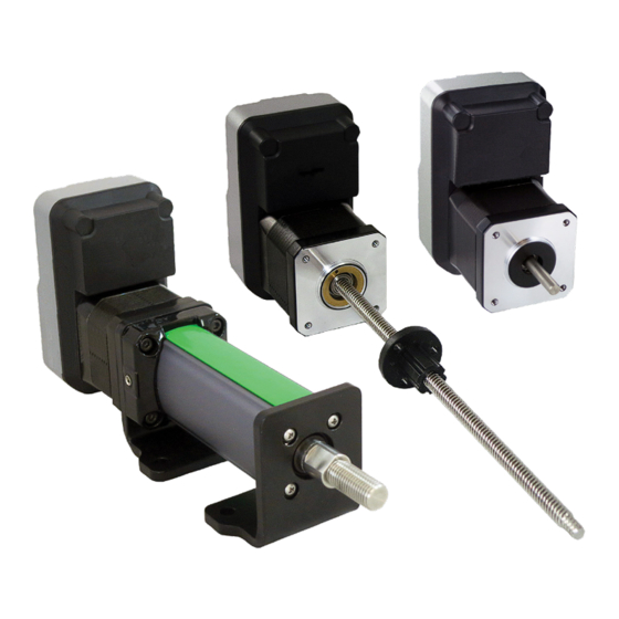
- Page 1 Hardware Manual Liberty MDrive CANopen NEMA 17 (42 mm) with Pluggable Connectors Publication IMS-MN-LMDA42_A 02/2022 REACH IP65 LISTED...
- Page 2 You also agree not to establish any hypertext links to this document or its content. Novanta IMS does not grant any right or license for the personal and noncommercial use of the document or its content, except for a non-exclusive license to consult it on an “as is” basis, at your own risk.
-
Page 3: Table Of Contents
Table of Contents Safety Information Important Information .......................5 Qualification of Personnel ......................5 Intended Use ..........................5 Product Related ...........................6 About this Manual Introduction ...........................8 Terminology Derived from Standards .................8 Source Documents and Software ..................9 Writing Conventions and Symbols ..................9 Documentation and Literature References ..............10 Website Directory ........................10 Documentation Feedback ......................10 Chapter 1: Introduction... - Page 4 Liberty MDrive CANopen Table of Contents Chapter 4: Installation Electromagnetic Compatibility, EMC ................. 44 Mechanical Installation ......................44 Supply Voltage VDC Connection ..................47 Multifunction Interface Connection ..................49 Signal Input Circuits ......................... 50 Signal Output Circuit ....................... 53 Analog Input ..........................53 Communications Interface Connection ................
-
Page 5: Safety Information
Qualification of Personnel Electrical equipment should be installed, operated, serviced, and maintained only by qualified personnel. No responsibility is assumed by Novanta IMS for any consequences arising out of the use of this material. A qualified person is one who has skills and knowledge related to the construction and operation of electro-mechanical equipment and its installation, and has received safety training to recognize and avoid the hazards involved. -
Page 6: Product Related
Liberty MDrive CANopen Product Related DANGER POTENTIAL FOR EXPLOSION Install and use this equipment in non-hazardous locations only. Failure to follow these instructions will result in death or serious injury. Any use other than the use explicitly permitted is prohibited and can result in hazards. Electrical equipment should be installed, operated, serviced, and maintained only by qualified personnel. - Page 7 UNINTENDED EQUIPMENT OPERATION • Do not open the LMD device housing for any reason. • Contact a Novanta IMS applications representative if the product exhibits unexplained, erratic, or incorrect operation. Failure to follow these instructions can result in death, serious injury, or equipment damage.
-
Page 8: About This Manual
ABOUT THIS MANUAL Introduction Read and understand the material contained in this manual before working on Liberty MDrive (LMD) products for the first time. Take particular note of the safety information (see “Safety Information” on page 5). Only qualified persons are allowed to work with the LMD product (see “Qualification of Personnel”... -
Page 9: Source Documents And Software
Source Documents and Software Liberty MDrive CANopen In addition, terms used in the present document may tangentially be used as they are derived from other standards such as: IEC 60034 series Rotating electrical machines IEC 61800 series Adjustable speed electrical power drive systems IEC 61158 series Digital data communications for measurement and control –... -
Page 10: Documentation And Literature References
The latest versions of these manuals can be downloaded from: https://novantaims.com/dloads/product-literature/manuals-3/ Website Directory NOTE: Direct links are subject to change as website and search engine updates occur. Each of the websites below can also be accessed through menu options on the Novanta IMS Main Page: https://novantaims.com/ Downloads: https://novantaims.com/dloads/ Resources: https://novantaims.com/resources/... -
Page 11: Chapter 1: Introduction
Chapter 1: Introduction What’s in this Chapter? This chapter contains the following topics: Topic Page About this Product Unit Overview Components and Interfaces Conditions for UL 508C Name Plate Part Number Identification IMS-MN-LMDA42_A... -
Page 12: About This Product
Liberty MDrive CANopen About this Product About this Product This manual is valid for the NEMA 17 (42mm) Liberty MDrive (LMD) CANopen product with pluggable connectors. This chapter lists the type code for this product. The type code can be used to identify whether the product is a standard product or a customized model. -
Page 13: Components And Interfaces
Components and Interfaces Liberty MDrive CANopen Components and Interfaces (A) Electronics housing (B) Two-phase stepper motor (C) DC power interface (D) Multifunction interface (E) CANopen interface (F) Protective earth (PE) (G) Light-emitting diode (LED) indicators Components Motor The motor is a two-phase brushless stepper motor. The step angle of the motor is 1.8°. Electronics Housing The electronics system is comprised of control electronics and the power stage. - Page 14 Liberty MDrive CANopen Components and Interfaces Multifunction Interface The multifunction interface operates at the following signal levels: • +12V to +24V Aux-Power input to supply power to logic circuits in the event of main supply loss. • +5 to +24V input signals are opto-isolated. •...
-
Page 15: Conditions For Ul 508C
Conditions for UL 508C Liberty MDrive CANopen Conditions for UL 508C The following conditions must be met if the product is used to comply with UL 508C. Ambient temperature during operation: • Surrounding air temperature [°C] 0 ... +50. Pollution degree: •... -
Page 16: Name Plate
Liberty MDrive CANopen Name Plate Name Plate The name plate contains the following information: (1) Part number (2) Nominal voltage (3) Max. Holding torque (4) Max required input current (5) Serial number (6) Date of manufacture (7) Communication interface (8) Data matrix (9) Ingress protection rating IMS-MN-LMDA42_A... -
Page 17: Part Number Identification
Part Number Identification Liberty MDrive CANopen Part Number Identification LMD Rotary Motor The following graphic displays a breakdown of the LMD rotary motor part number identification. LMD O A 42 Product LMD = standard torque motor Feedback O = Open loop (no encoder) C = Closed loop (with encoder) A = Absolute encoder Control Type... - Page 18 Liberty MDrive CANopen Name Plate LMD External Linear Actuators The following graphic displays a breakdown of the LMD external linear actuator part number identification. LMD O A 42 1 P -L A 3 M 030 G T Product LMD = standard torque motor Feedback O = Open loop (no encoder) C = Closed loop (with encoder)
- Page 19 Name Plate Liberty MDrive CANopen LMD Electric Cylinders (eCylinders) The following graphic displays a breakdown of the LMD eCylinder part number identification. LMD O A 42 1 P -C S A 020 M NN Product LMD = standard torque motor Feedback O = Open loop (no encoder) C = Closed loop (with encoder)
-
Page 20: Chapter 2: Technical Data
Chapter 2: Technical Data What’s in this Chapter? This chapter contains information on the ambient conditions and on the mechanical and electrical properties of the device family and accessories. This chapter includes the following topics: Topic Page Certifications Environmental Conditions Mounting Data Mechanical Data Electrical Data... -
Page 21: Certifications
Certifications Liberty MDrive CANopen Certifications Certification Regulation # RoHS 2011/65/EU, 2015/863 2004/108/EC REACH EC 1907/2006 UL 1004-1, UL 1004-3 CSA C22.2 No. 100 CSA C22.2 No. 77 A current list of certifications and compliance information can be viewed at: https://novantaims.com/dloads/certificationssustainability/ Environmental Conditions Ambient Operating Conditions The maximum permissible ambient temperature during operation depends on the distance... -
Page 22: Mounting Data
Liberty MDrive CANopen Mounting Data Emission IEC61800-3 (Category C2) Noise immunity IEC61000-6-2 IP Degree of Protection The product has the following degree of ingress protection (IP) as per EN 60529. Degree of protection IP20 The total degree of protection is determined by the component with the lowest degree of protection. - Page 23 Mounting Data Liberty MDrive CANopen Mounting (Rotary and External Linear Actuators) Mounting the LMDXA42X uses four (4) M3 x 0.5 screws on a bolt circle diameter (BCD) of 1.725” (43.81 mm). The length of the screws will be determined by the thickness of the mounting material plus a maximum of 0.140”...
- Page 24 Liberty MDrive CANopen Mounting Data Mounting (Electric Cylinder with Foot Mount) The electric cylinder LMD products foot mount option has front and rear foot mounting plates for mounting the cylinder into the system. The following graphic shows the mounting hole dimensions for the foot mounting plates.
-
Page 25: Mechanical Data
Mechanical Data Liberty MDrive CANopen Mechanical Data NOTICE EXCESSIVE RADIAL OR AXIAL LOADS Radial (side) loading or axial (thrust) impacts on the shaft may result in premature bearing wear and eventual destruction of the bearing. • Do not place unsupported radial or side loads on the motor shaft. •... - Page 26 Liberty MDrive CANopen Mechanical Data External Linear Actuator Dimensions The following graphic shows the external linear actuator dimensions of the NEMA 17 (42 mm) [inches (mm)]. 1.450 (36.83) Screw end options: smooth end (shown), metric, UNC, or none 3.449 (87.60) Ø...
- Page 27 Mechanical Data Liberty MDrive CANopen Electric Cylinder Mechanical Specifications Electric cylinder range of motion is limited by the stroke length with the cylinder rod end acting as a hard stop. Running the cylinder into a hard stop can damage the internal components of the cylinder.
- Page 28 Liberty MDrive CANopen Mechanical Data Foot Mounts The following graphic shows the dimensions for the LMD electric cylinder with the foot mounting option. 5.55 (140.9) max + Stroke Length 2.06 (52.3) 1.45 (36.8) Stroke Lengths may range from 1.67 (42.4) 2.0 (51) min.
-
Page 29: Electrical Data
Electrical Data Liberty MDrive CANopen Electrical Data This section provides an overview of the LMD connection specifications and LED status information. LED 2 LED 1 Chassis P1 Connector - Supply Voltage (VDC) Refer to the following table for LMD•42 supply voltage information. LMD•42 Nominal voltage [+Vdc]... - Page 30 Liberty MDrive CANopen Electrical Data P2a and P2b Connectors - Multifunction Interface Signal Inputs The signal input functions are programmable in function They may be used as sinking or INPUT _ REFERENCE sourcing based upon the bias of the Voltage range [+Vdc] 5 ...
- Page 31 Electrical Data Liberty MDrive CANopen LED Indicators The LMD has two LEDs for status indication. • LED 1: Status of the power supply • LED 2: The CANopen status LED shows the states as specified in the CAN in Automation (CiA) DR-303-3, Indicator Specification. Color State Status...
-
Page 32: Rotary Motor Data
Liberty MDrive CANopen Rotary Motor Data Rotary Motor Data Rotary Specifications Single Double Triple Holding torque oz-in (N-cm) 44 (31) 58 (41) 88 (62) Detent torque oz-in (N-cm) 1.7 (1.2) 2.1 (1.5) 3.5 (2.5) Rotor inertia oz-in-sec (kg- 0.0005 (0.038) 0.0008 (0.057) 0.0012 (0.082) Radial load limit:... -
Page 33: External Linear Actuator Data
External Linear Actuator Data Liberty MDrive CANopen External Linear Actuator Data Linear Actuator Specifications The following table shows the external linear actuator specifications for the LMD•42: Specifications Units Value Rotor inertia oz-in-sec2 0.0005 kg-cm2 0.038 Maximum screw misalignment degrees ±1 Maximum thrust general purpose nut anti-backlash nut... -
Page 34: Electric Cylinder Data
Liberty MDrive CANopen Electric Cylinder Data Electric Cylinder Data Electric Cylinder Specifications The table below lists the electric cylinder actuator specifications for the LMD•42: Specifications Units Value Rotor inertia oz-in-sec 0.0005 kg-cm 0.038 Maximum thrust PEEK blend nut Accuracy ± inches per inch 0.0003 ±... -
Page 35: Chapter 3: Engineering
Chapter 3: Engineering What’s in this Chapter? This chapter contains information on the application of the product that is vital in the design phase. This chapter includes the following topics: Topic Page External Power Supply Units Auxiliary Power Supply Wiring and Shielding Ground (Earth) Design Monitoring Functions IMS-MN-LMDA42_A... -
Page 36: External Power Supply Units
Liberty MDrive CANopen External Power Supply Units External Power Supply Units The VDC, AUX_PWR, and INPUT_REFERENCE supply voltages are connected with many exposed signal connections in the drive system. DANGER ELECTRIC SHOCK POSSIBLE • Use an DC power supply unit that meets voltage requirements. •... - Page 37 External Power Supply Units Liberty MDrive CANopen CAUTION LOSS OF CONTROL DUE TO REGENERATION CONDITION Regeneration conditions resulting from braking or external driving forces may increase the VDC supply voltage to an unexpected level. Components not rated for this voltage may be destroyed or cause malfunctions.
- Page 38 Liberty MDrive CANopen External Power Supply Units The graphic below shows power supply cabling 50’ (15.2 m) or greater, AC power to a full wave bridge. To the DC Power Supply Cable ≥ 50’ (15.24 m) Shield to Earth Ŀ Type RFI Filter ≥ Required Current (Supply End Only) Transformer: 10 to 28 VAC RMS Shielded Twisted Pair (See AWG Table for Size)
-
Page 39: Auxiliary Power Supply
Auxiliary Power Supply Liberty MDrive CANopen Auxiliary Power Supply The auxiliary logic supply is an optional power supply used to provide power to the logic circuitry of the LMD in the event of main system power outage. This supply will retain all system data. -
Page 40: Ground (Earth) Design
Liberty MDrive CANopen Ground (Earth) Design +VDC GND AUX GND +VDC Supply AUX Supply Ground (Earth) Design The ground (earth) connections of all interfaces are connected, including the ground for the VDC supply voltage. The exception to this is the logic ground connection of the I/O interface, which is optically isolated. -
Page 41: Monitoring Functions
Monitoring Functions Liberty MDrive CANopen Equipotential Bonding Conductors Potential differences can result in excessive currents on the cable shields. Use equipotential bonding conductors to reduce currents on the cable shields. The equipotential bonding conductor must be rated for the maximum current flowing. Practical experience has shown that the following conductor cross sections can be used: •... -
Page 42: Chapter 4: Installation
Chapter 4: Installation What’s in this Chapter? This chapter includes the following topics: Topic Page Electromagnetic Compatibility, EMC Mechanical Installation Supply Voltage VDC Connection Multifunction Interface Connection Signal Input Circuits Signal Output Circuit Analog Input Communications Interface Connection Checking Wiring IMS-MN-LMDA42_A... - Page 43 Liberty MDrive CANopen WARNING INCORRECT INSTALLATION Ensure the correct installation and maintenance of the system according to the instructions contained in the present document and other supporting documents. Failure to follow these instructions can result in death, serious injury, or equipment damage. The designer of any control scheme must consider the potential failure modes of control paths and, for certain critical functions, provide a means to achieve a safe state during and after a path failure.
-
Page 44: Electromagnetic Compatibility, Emc
Liberty MDrive CANopen Electromagnetic Compatibility, EMC Electromagnetic Compatibility, EMC This product meets the EMC requirements in accordance with the standard IEC 61800-3, provided that the EMC measures described in this manual are complied with during installation. If not, signal interference can cause unexpected responses of device. WARNING SIGNAL AND DEVICE INTERFERENCE •... - Page 45 Mechanical Installation Liberty MDrive CANopen WARNING MOTOR WITHOUT BRAKING EFFECT If power outage and faults cause the power stage to be switched off, the motor is no longer stopped by the brake and may increase its speed even more until it reaches a mechanical stop. •...
- Page 46 Liberty MDrive CANopen Mechanical Installation Mounting The motor is designed to be mounted using four screws. The motor flange must be mounted on a flat surface to avoid mechanical tension from being transmitted to the housing. Painted surfaces have an insulating effect. During mounting verify that the motor flange is mounted in such a way as to allow for good electrical and thermal conductivity.
-
Page 47: Supply Voltage Vdc Connection
Supply Voltage VDC Connection Liberty MDrive CANopen LMD Connectors Overview This section provides an overview of the LMD connectors. Refer to “Electrical Data” on page 29 for the electrical specifications for these connectors. LED 2 LED 1 Chassis Connector Assignment Supply voltage VDC Multifunction interface Communication interface... - Page 48 Liberty MDrive CANopen Supply Voltage VDC Connection Pin Assignment The graphic and table below show the DC power connection pin assignment. Signal Function Pin number +12 to +48 VDC Supply voltage 0 VDC Reference potential to VDC Wiring/cable Specifications Use shielded twisted pair cabling for the supply voltage •...
-
Page 49: Multifunction Interface Connection
Multifunction Interface Connection Liberty MDrive CANopen Multifunction Interface Connection NOTE: On LMD products with a multi-turn Absolute Encoder, the Analog input located at P2a, pin 6 is replaced by the External Battery pack inputs: See Appendix D on page 71 for details specific to the Absolute Encoder variant. -
Page 50: Signal Input Circuits
Liberty MDrive CANopen Signal Input Circuits Connecting the Cable The connector is a spring clamp type terminal strip. To interface: • Strip 0.25” (6.0 mm) insulation. • Use a small screwdriver to push in the designated pin’s spring clamp. • Insert stripped wire into designated pin. •... - Page 51 Signal Input Circuits Liberty MDrive CANopen Open collector (sinking): INPUT_REF Constant Current Source INPUT Open collector (sourcing): INPUT_REF Constant Current Source INPUT Signal Input Wiring and Usage Examples Mechanical Switches Sinking Operation: In the schematic below, the inputs will float at a 24V level (HIGH), then be at ground (LOW) when the switch is closed.
- Page 52 Liberty MDrive CANopen Signal Input Circuits NPN Sensors in a Sinking Home/limit ± Configuration A common configuration is to have two sensors which define the PLUS and MINUS limits of travel, and a third to home the axis. The following illustrates three NPN sensors connected to the LMD inputs 2 - 4 in that configuration.
-
Page 53: Signal Output Circuit
Signal Output Circuit Liberty MDrive CANopen Signal Output Circuit The signal output provides indication of trip condition(s). The condition(s) which will trigger this output are programmable. The output is galvanically isolated by means of an optic isolation. Signal output: COLLECTOR EMITTER PLC input or high speed latch... -
Page 54: Communications Interface Connection
Liberty MDrive CANopen Communications Interface Connection Refer to the LMD MCode manual, or the appropriate fieldbus manual for full setup and configuration details for the analog input. Loop Range MCode setup string Notes (Is=5,[mode],[range]) Voltage 0 to 5V Is=5, 9, 0 Set input to voltage mode, 0 to 5 volt range 0 to 10V IS=5, 9, 1... -
Page 55: Checking Wiring
Checking Wiring Liberty MDrive CANopen Terminating Resistor Both ends of the entire bus system must be terminated with a terminating resistor. The resistor value is 120Ω connected between the CAN_H and CAN_L lines. Setting the Address and BAUD Rate Each device on the network is identified by a unique, adjustable node ID which may be set using the CANopen Configuration Utility, which is part of the LSS, or by using CANopen Layer Setting Service as defined in CiA document DSP-305. -
Page 56: Chapter 5: Configuration
Chapter 5: Configuration What’s in this Chapter? This chapter includes the following topics: Topic Page Preparing for Configuration Configuration via Layer Setting Services IMS-MN-LMDA42_A... - Page 57 Liberty MDrive CANopen Drives may perform unintended movements because of incorrect wiring, incorrect settings, incorrect data, or other errors. Interference (EMC) may cause unpredictable responses in the system. Further, the behavior of the drive system is governed by stored data or settings. Unsuitable settings or data may trigger unintended movements or responses to signals and disable monitoring functions.
-
Page 58: Preparing For Configuration
Liberty MDrive CANopen Preparing for Configuration CAUTION HOT SURFACES • Avoid unprotected contact with hot surfaces. • Do not allow flammable or heat-sensitive parts in the immediate vicinity of hot surfaces. • Verify that the heat dissipation is sufficient by performing a test run under maximum load conditions. -
Page 59: Chapter 6: Operation
Chapter 6: Operation What’s in this Chapter? This chapter describes the basic functions of the drive. This chapter includes the following topics: Topic Page Basics CANopen DSP402 Operation Modes Operation by hMT Modes I/O Operation IMS-MN-LMDA42_A... -
Page 60: Basics
Liberty MDrive CANopen Basics Basics Mode of Operation The “LMD CANopen”, which uses DS301 communication profile, is the interface between device profiles and CAN bus. It was specified in 1995 under the name DS301 and defines uniform standards for common data exchange between different device types under CANopen. The DSP402 device profile describes standardized objects for positioning, monitoring, and settings of drives. - Page 61 Basics Liberty MDrive CANopen The following graphic shows the control bounds for hMT. hMT maintains the rotor/stator relationship within the set control bounds LEAD Best torque performance Stall zone Stall zone > 2 full steps > 2 full steps Best overall performance Best speed performance Hybrid Motion Technology uses a high speed feedback loop to tightly maintain the rotor/stator relationship within a specified range, or control bounds.
-
Page 62: Canopen Dsp402 Operation Modes
Liberty MDrive CANopen CANopen DSP402 Operation Modes Refer to the following graphic for an overview of motor phase current. Fixed or variable current AS = 0 AS = 1 AS = 2 (variable) AS = 3 (variable) Run current Hold current RC=[0...100%] HC=[1...100%] ACTUAL... - Page 63 CANopen DSP402 Operation Modes Liberty MDrive CANopen Profile Velocity Mode The profile velocity mode covers the following sub-functions: • Demand value input via trajectory generator. • Velocity capture using position sensor or velocity sensor. • Velocity control function with appropriate input and output signals. •...
-
Page 64: Operation By Hmt Modes
Liberty MDrive CANopen Operation by hMT Modes Operation by hMT Modes The LMDxC, LMDCx, and LMDAx feature four operational modes for hMT: 1. hMT off 2. hMT on (fixed current) 3. hMT on (variable current) 4. Torque control The selected mode will have a major effect on how the device will operate during a move. The hMT operating mode may also be changed either programmatically or immediately provided a move is not in progress. -
Page 65: I/O Operation
I/O Operation Liberty MDrive CANopen The following graphic shows a block diagram for a system with hMT enabled: hMT Logic Rotor actual Position position Compare Lead/Lag logic Register Stator commanded position Velocity Generator Encoder Motor Bridge Current Bridge Control hMT On (Variable Current) With hMT enabled in variable current mode, hMT will function the same as described for fixed current mode with the difference that current control will be in variable mode. -
Page 66: Appendix A: Diagnostics And Troubleshooting
Appendix A: Diagnostics and Troubleshooting Operation State and Error Indication Temperature Monitoring Sensors in the drive measure the temperature of the power stage. If the permissible maximum temperature is exceeded, the power stage is de-energized. Indication is displayed by reading object 2019h Output h-bridge temperature options, subindex 01h. -
Page 67: Appendix B: Accessories And Spare Parts
Appendix B: Accessories and Spare Parts Accessories Source Commissioning Software The latest version of the CANopen Configuration Utility, part of the LSS, available for download from https://novantaims.com/dloads/ Communications Converter Description Part number USB to CANopen communication converter MD-CC501-000 The communication converter kit contains a converter, a six foot cable, and a terminating resistor plug. -
Page 68: Appendix C: Service, Maintenance, And Disposal
UNINTENDED EQUIPMENT OPERATION • Do not open the LMD housing for any reason. • Contact a Novanta IMS service representative if the product exhibits unexplained erratic or incorrect operation. Failure to follow these instructions can result in death or serious injury. -
Page 69: Service Address
Service Address If an error cannot be resolved from the information provided in this manual, contact a Novanta IMS service representative. Have the following details available: • Nameplate (type, identification number, serial number, DOM, ...) • Type of error (e.g., LED flash code, error number. etc.) •... -
Page 70: Shipping, Storage, And Disposal
Liberty MDrive CANopen Shipping, Storage, and Disposal Only start the system if there are no persons or obstructions in the zone of operation. • Switch off all supply voltages. Verify that no voltages are present. • Label all connections and uninstall the product. •... -
Page 71: Appendix D: Liberty Mdrive With Absolute Encoder
Appendix D: Liberty MDrive with Absolute Encoder Overview This appendix covers the multi-turn absolute encoder functions for LMD CANopen products. The multi-turn absolute encoder holds and updates the position information regardless of the powered on/off state of the LMD device. The absolute position in memory is powered by an internal source for up to 30 days, or by an external battery pack for up to five years. -
Page 72: Icp0531 Encoder Back-Up Battery Pack
Liberty MDrive CANopen ICP0531 Encoder Back-up Battery Pack ICP0531 Encoder Back-up Battery Pack The optional Encoder Back-up Battery Pack (ICP0531) will provide back-up power for the LMD Absolute Encoder circuitry, retaining and updating the position data for a period of up to five (5) years. - Page 73 ICP0531 Encoder Back-up Battery Pack Liberty MDrive CANopen Installing/Replacing the Batteries NOTE: Use only Energizer L91 1.5V AA Lithium batteries. CAUTION Do not load or transport lithium ion batteries if the packaging is damaged. A flammability hazard exists if package is damaged. Handle with care. Attention: If Lithium batteries are installed, provide proper package warning labels to all shipping containers as required by law.
- Page 74 Liberty MDrive CANopen ICP0531 Encoder Back-up Battery Pack Connector Configuration J1-J8: Encoder Backup Voltage To connect encoder battery backup power to a single Absolute MDrive product, use development cable PD02-0531-FL1 (shown below). 3.3 ft (1.0m) VBAT+ VBAT- Housing P/N Crimp Pin P/N Crimp Pin Qty 280358-0 182206-2...
- Page 75 ICP0531 Encoder Back-up Battery Pack Liberty MDrive CANopen Connecting the Encoder Battery Pack The following diagram shows the connection of the optional Encoder Back-up Battery Pack (ICP0531). IMS-MN-LMDA42_A...
-
Page 76: Glossary
GLOSSARY AC: Alternating current Acceleration: The time rate of change of velocity with respect to a fixed reference frame. The commanded step rate is started at a base velocity and accelerated at a slew velocity at a defined and controlled rate or rate of changes. ASCII: American Standard Code for Information Interchange. - Page 77 Glossary Liberty MDrive CANopen EMC: Electromagnetic compatibility Encoder: Sensor for detection of the angular position of a rotating component. The motor encoder shows the angular position of the rotor. Error: Operating state of the drive caused as a result of a discrepancy between a detected (computed, measured, or signaled) value or condition and the specified or theoretically correct value or condition.
- Page 78 Liberty MDrive CANopen Glossary Locked Rotor: When the lag/lead limit is reached, a timer starts a countdown that is determined by the user. The locked rotor will assert itself by triggering a flag and, depending on the selected mode, by disabling the output bridge. Loss of synchronization: In traditional stepper systems, when the lead/lag relationship of the rotor and stator reaches two full motor steps, the alignment of the magnetic fields is broken and the motor will stall in a freewheeling state.
- Page 79 Glossary Liberty MDrive CANopen Resolution: The smallest positioning increment that can be achieved. Resonance: The frequency that a stepper motor system may begin to oscillate. Primary resonance frequency occurs at about one revolution per second. This oscillation will cause a loss of effective torque and may result in loss of synchronism.
- Page 80 Warranty For the latest warranty and product information, visit: https://novantaims.com/warranty-and-disclaimer/ Document Revision History Liberty MDrive CANopen: IMS-MN-LMDA42_A Date Revision Changes Reformatting for company name change. New document number 02/09/2022 Rev A applied.
- Page 81 Novanta IMS is a part of the Precision Motion Group within Novanta, a leading technology company that delivers innovation to medical and advanced industrial OEMS. As standards, specifications, and designs may change, confirmation of the information given in this publication can be found in the product disclaimer and most recent product information, available online.
Need help?
Do you have a question about the LMD17 and is the answer not in the manual?
Questions and answers