Table of Contents
Advertisement
Quick Links
Advanced Airport Lighting System
Precision Approach Path Indicator
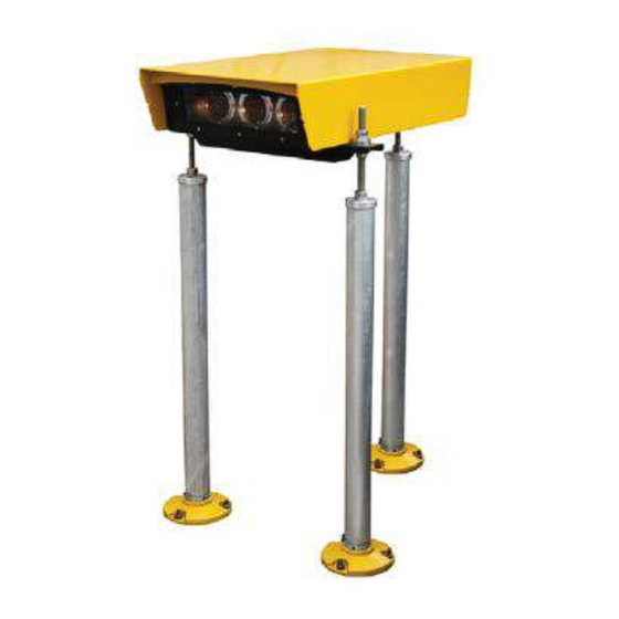
PAPI-300 (PDL-620)
Operation Manual
Please read this manual carefully before construction, installation and operation of the product.
Please keep this manual properly for further reference.
This manual is subject to change without prior notice.
Airsafe Airport Equipment Co., Ltd.
1
Advertisement
Table of Contents
Troubleshooting

Related Manuals for Airsafe PAPI-300

Summary of Contents for Airsafe PAPI-300
- Page 1 Precision Approach Path Indicator PAPI-300 (PDL-620) Operation Manual Please read this manual carefully before construction, installation and operation of the product. Please keep this manual properly for further reference. This manual is subject to change without prior notice. Airsafe Airport Equipment Co., Ltd.
- Page 2 Advanced Airport Lighting System Revision Description Approved Description Version No. Revised by Date First release V1.0 Y. YH C. SY Apr. 10, 2008 Gateway contents added V1.1 ZH and G. JH X. CL Nov. 20, 2016 and composing adjusted...
-
Page 3: Table Of Contents
Advanced Airport Lighting System Table of Content 1.0 Foreword ............................5 1.1 Illustrations and Meanings ....................5 1.2 Safety Rules and Notices ..................... 6 1.3 Quality Assurance and Responsibility ................7 2.0 Introduction ..........................8 2.1 Technical Specifications ...................... 9 2.2 Application Environment .................... - Page 4 Advanced Airport Lighting System 9.0 Packaging, Transportation and Storage .................. 52 9.1 Packaging and Weight ...................... 52 9.2 Transportation Mode ......................52 9.3 Storage..........................52...
-
Page 5: Foreword
Advanced Airport Lighting System 1.0 Foreword ICAO Airport Service Manual Part 9 “Airport Maintenance Practices” and FAA AC150/5345-26 Maintenance of Airport Visual Aid Facilities are the highest criterions for site installation and maintenance of such lighting fixtures. This manual was compiled with considerable reference to these two criterions. -
Page 6: Safety Rules And Notices
Advanced Airport Lighting System 1.2 Safety Rules and Notices Using the light fixtures outside of airport is strictly prohibited. ※ Inadequate maintenance or casual touch will cause light faults. Be careful when handling the precision approach path indicator. ※... -
Page 7: Quality Assurance And Responsibility
Advanced Airport Lighting System 1.3 Quality Assurance and Responsibility Any defect in design, material or workmanship, which may occur during proper and normal use over a period of one year from date of installation but less than 15 months from date of shipment, or within the warranty period of the tender, will be repaired or preplaced by manufacturer free of charge. -
Page 8: Introduction
PAPI is equipped a 300W/6.6A isolation transformer, which is installed under the lamp or additional separated position. PAPI system (PAPI-300-R) with the monitoring module is suggested, whose system state and failure information may be fed back to the lamplight station through... -
Page 9: Technical Specifications
Using the lighting fixtures beyond the specified scope is strictly prohibited. ※ Application beyond the specified scope will cause damage or risk to any component. 2.4 Technical Parameters Life of light source at 6.6A Description Type Rated Power ≥1,000h Precision approach path indicator PAPI-300 3×10⁵W... -
Page 10: Technical Features
Advanced Airport Lighting System 2.5 Technical Features • Grading and color of the lighting fixtures meet the requirements of Attachment 14 of ICAO; • Proprietary optical system design makes excellent red and white transition of PAPI and straight transition line; •... -
Page 11: Structure
Advanced Airport Lighting System 2.6 Structure 2.6.1 Key Components of Upper Box 1. Upper cover plate assy 2. Dust cover plate 3. Seal pressing bracket 4. Front glass (assy) 5. Box 6. Temperature controlled switch 7. Transformer 8. Longitudinal level module 9. -
Page 12: Key Components Of Landing Leg Assy
Advanced Airport Lighting System 2.6.2 Key Components of Landing Leg Assy 1. Flange 2. Landing leg 3. Front cover of landing leg 4. Tapping screw ST5.5 5. Spring washer 16 6. Screw 7. Hex nut M16 8. Hex thin nut M16 9. -
Page 13: Interpretation Of System Terminology
Advanced Airport Lighting System 2.7 Interpretation of System Terminology 2.7.1 Elevation The beam centers of all lighting fixtures in the PAPI system aim at the approach slope according to the defined subtle deviation and the elevation means the included angle of the beam center of the lighting fixtures and the horizontal plane. -
Page 14: Key Buttons And Plug-Ins
Advanced Airport Lighting System 2.7.2 Key Buttons and Plug-ins The general framework of the PAPI control panel is shown in Figure below and definitions of the key buttons and plug-ins are as follows: SW1: Setting state switching jumper cap (switching between “Factory Mode” and “User Mode”);... - Page 15 Advanced Airport Lighting System After this system is powered on, the panel control will automatically enter “Operation” and have the function to automatically recover “Operation” with unmanned operation under “Calibrate Flight” to prevent misoperation by the airport personnel. Four-digit Nixie tube: There is a four-digit Nixie tube embedded on the PAPI control panel (as shown in Figure DS1 below), which timely displays the current mode and elevation of PAPI.
-
Page 16: Two Working Conditions And Four Modes
Advanced Airport Lighting System 2.7.3 Two Working Conditions and Four Modes This PAPI system has two working conditions and four modes, whose relations are shown in Figure below: “Factory Mode” and “User Mode” of PAPI are switched through SW1. (1) “Factory Mode”: When PAPI is in “Factory Mode”, the Nixie tube only displays the current angle. - Page 17 Advanced Airport Lighting System (2) “User Mode”: When PAPI leaves the factory, the system is in “User Mode” and PAPI executes various operations. “User Mode” includes “Calibrate Flight” and “Operation”, which are fixed programs of the lighting fixtures. Under “User Mode”, SW2 is used for switching of various modes and the user may switch “Calibrate Flight”...
- Page 18 Advanced Airport Lighting System (3) “Calibrate Flight” During flight calibration or daily maintenance, the system shall set PAPI to “Calibrate Flight”. Under this mode, PAPI will not have “Error”, but turn off the lamp to ensure normal on-going flight calibration or maintenance. The display method of the four-digit Nixie tube is 4 characters initiated by the letter C (the Nixie tube displays “C+ value of the current elevation”), with the display shown in Figure below: Display under “Calibrate Flight”...
- Page 19 Advanced Airport Lighting System (4) “Operation” After this system is powered on, the control panel will automatically enter “Operation”. Under “Operation”, PAPI works normally and achieves control of various states, including such preset functions as error alarm. Therefore, after the flight calibration or daily maintenance is completed, PAPI is switched to “Operation”...
- Page 20 Advanced Airport Lighting System (5) “Memory Angle”: Press the SW2 button for longer than 5s to store the current angle confirmed through flight calibration into the PAPI system. We call the angle stored into the system “Memory Angle”. The expression form of “Memory Angle” is four characters initiated by the letter F displayed by the four-digit Nixie tube (the Nixie tube displays “F+ currently memory angle”): Display under “Memory Angle”...
- Page 21 Advanced Airport Lighting System (6) “Error” When the control panel detects the anomaly of the PAPI system, it turns off the system lamp within several seconds and the error will be prompted on the Nixie tube. This function of the system is called “Error”. The system provides two kinds of “Errors”: The operating angle deviation is greater than the specified value: Under “Operation”, when the PAPI angle is 0.38°...
-
Page 22: Installation Of Lighting Fixtures
Advanced Airport Lighting System 3.0 Installation of Lighting Fixtures From the view of the runway threshold, the PAPI or APAPI system shall be set on the left of the runway, unless it is impossible according to the actual situation. The PAPI system must consist of four lighting fixture units with equal distance. The APAPI system must consist of two lighting fixture units with equal distance. -
Page 23: Boundary Dimension
Advanced Airport Lighting System 3.2 Boundary Dimension The maximum installation height of the lighting fixtures is 900mm and the dimension of the corresponding luminous center is 820mm. Figure 3-3... -
Page 24: On-Site Installation Of Papi Lighting Fixtures
Advanced Airport Lighting System 3.3 On-site Installation of PAPI Lighting Fixtures In order to ensure the operating stability of the PAPI system, the manufacturer suggests that the PAPI lighting fixtures should be installed on a prefabricated cement foundation. For the dimension of the prefabricated cement foundation, please refer to the Figure below. - Page 25 Advanced Airport Lighting System When embedding the foundation bolt in the cement foundation, the auxiliary installation sample (Figure 3-4) may be used. According to the position of the lighting fixtures, 9Ф10 holes position the position of the embedded bolt. For the installation of the lighting fixtures, the manufactures distributes a set of installation sample.
-
Page 26: Installation Of Landing Leg
Advanced Airport Lighting System 3.3.2 Installation of Landing Leg First, put three flanges into the embedded foundation bolt and fix them with nuts. According to the height design requirements of PAPI and on-site actual situation, determine the length of the extension pole of the PAPI lighting fixtures. Please note that the lengths of the extension pole of four lighting fixtures are inconsistent. -
Page 27: Same Height Setting Of Lighting Fixture Set
Advanced Airport Lighting System 3.3.3 Same Height Setting of Lighting Fixture Set When the PAPI lighting fixture system is installed, it must be ensured that the bean centers of four luminous units are on the same level while ensuring that the height of the beam center of the PAPI system meets the design requirements. - Page 28 Advanced Airport Lighting System Screw Upper and lower spherical washers Hex nut M16 Hex thin nut M16 Cross pan head tapping Front cover of landing leg screw ST5.5×19 Landing leg Local view A Scale 1:3 Figure 3-7 The height error of the beam center (lens center) of all lighting fixtures adjusted is not greater than 5cm.
-
Page 29: Electrical Wiring Of Lighting Fixtures
Advanced Airport Lighting System 3.3.4 Electrical Wiring of Lighting Fixtures PAPI has an external junction box and wiring of PAPI may be completed externally. The external junction box is often placed in the auxiliary isolation transformer tank of PAPI. Waterpro Waterproof gland of of gland... - Page 30 Advanced Airport Lighting System Circuit Circuit Circuit Circuit 电路板 电路板 电路板 电路板 board board board board Lightning Lightning Lightning Lightning 防雷模块 防雷模块 防雷模块 protection module 防雷模块 protection module protection module protection module BUS+ BUS+ 6.6A 6.6A 6.6A BUS+ 6.6A BUS+ BUS- BUS- 300W...
- Page 31 Advanced Airport Lighting System If PAPI has the remote monitoring mode (PAPI-300-R), the corresponding installation method is shown in Figure below: CAN转接板 CAN转接板 CAN adapter plate CAN转接板 CAN转接板 CAN adapter plate CAN adapter plate CAN adapter plate Circuit Circuit 电路板...
- Page 32 Advanced Airport Lighting System ■ CAN connection requires to distinct the cable color. Please perform wiring in strict accordance with the requirements of the specification. ※ Any wiring problems may cause abnormal work of the system. ■ Making sure that all wiring is firm and reliable. ※...
-
Page 33: Adjustment And Setting Of Lighting Fixture Elevation
Advanced Airport Lighting System 3.3.5 Adjustment and Setting of Lighting Fixture Elevation Four PAPI units placed on site have different elevations respectively. Therefore, elevation setting is an important step for installing the PAPI lighting fixture units. The correct elevation ensures that the PAPI system works. According to the provisions, the unit with the greatest elevation in the PAPI system shall be at the position close to the runway and that with the lowest elevation in the PAPI system shall be on the most outside which is the farthest from the runway. - Page 34 Advanced Airport Lighting System Due to mutual impacts of the horizontal level and longitudinal angle, the fine adjustment of the horizontal level indicator and longitudinal elevation must be made alternately and repetitively. M16 hex nuts are finally used for locking (see Section 3.3.3).
-
Page 35: Flight Calibration Inspection And Adjustment Of Lighting Fixtures
Advanced Airport Lighting System 4.0 Flight Calibration Inspection and Adjustment of Lighting Fixtures Before the PAPI system is formally put into use, an flight calibration must be performed. The airport may independently perform the flight calibration for the PAPI system, or arrange it with that of the airport runway at the same time. -
Page 36: Disposal After Flight Calibration
Advanced Airport Lighting System 4.1 Disposal after Flight Calibration After flight calibration, the correct elevations of all lighting fixtures obtained through flight calibration must be recorded and archived for maintenance reference in the future. Except production of various documents specified by the airport management authority and flight calibration procedures, this PAPI system provides the following storage. - Page 37 Advanced Airport Lighting System (2) Memory through longitudinal level indicator Unscrew the adjusting screw in Figure below and the rack will rotate along the spindle to make the bubble in the longitudinal level indicator locate in the middle of the scale. ■...
-
Page 38: Replacement Of Components Of Lighting Fixtures
Advanced Airport Lighting System 5.0 Replacement of Components of Lighting Fixtures When any damage or failure occurs to any consumable or other component of the lighting fixtures, it is required to timely dismantle the lighting fixtures for replacement of the component. Replacement of components needs to dismount the lighting fixtures, so any minor error will cause adverse consequences. -
Page 39: How To Replace Lamp
Advanced Airport Lighting System 5.1 How to Replace Lamp If one lamp in certain PAPI lighting fixture is found to be damaged during daily inspection and maintenance, the user shall immediately replace a new lamp. If the PAPI control panel monitors that two lamps in certain lighting fixture are damaged, this unit will enter “Error”... - Page 40 Advanced Airport Lighting System ■ Touching the lamp directly with hands is strictly prohibited. ※ Otherwise it may burn the skin. ■ Touching the lamp cup with hands is prohibited when replacing a new lamp. ※Touching the lamp cup with hands is one of causes to cause its explosion.
-
Page 41: How To Replace Filter
Advanced Airport Lighting System 5.2 How to Replace Filter Before replacing the filter, first turn off the CCR power source of the relevant circuit. Take out the old filter: Open the upper cover of the PAPI lighting fixtures and internal dust cover plate as shown in Figures (in order shown in Figures 1 and 2); Wear the cotton gloves, which shall be washed once at least. -
Page 42: How To Replace Control Panel
Advanced Airport Lighting System 5.3 How to Replace Control Panel Before replacing the control panel, first confirm and record the current accurate angle. If it is impossible to read the “Memory Angle” on the control panel, it may be obtained from the longitudinal level indicator. ■... - Page 43 Advanced Airport Lighting System When the angle is adjusted, the force to pressing the button shall not be too great, otherwise it may cause the deformation of the control panel, so as to impact the angle inspection. When the angle is set, if the set value is greater than the value recorded, continuously press the button and start to count from 0.00°...
-
Page 44: Maintenance Of Precision Approach Path Indicator
Advanced Airport Lighting System 6.0 Maintenance of Precision Approach Path Indicator 6.1 Daily Inspection and Maintenance Maintenance of the lighting fixtures shall comply with the “Airport Maintenance Practice” of Section 9 of ICAO’s Airport Service Manual and FAA’s AC150/5345-26 Maintenance of Visual Navaids at Airport. Because the PAPI system is a very precision optical system, the daily maintenance must be performed by the professional. - Page 45 Advanced Airport Lighting System ■ Making sure that the light intensity of PAPI and the boundary between red and white is clear ※ Otherwise it may cause incorrect judgment of the pilot. IV. Inspection of PAPI fixation. Check that all adjusting nuts on the landing leg are locked and the chassis connection is reliable.
-
Page 46: Troubleshooting Of Common Error Of Control Panel
Advanced Airport Lighting System 6.1.2 Troubleshooting of Common Error of Control Panel Under “Operation”, when the elevation of any unit in the PAPI system is greater than the set limit or all lamps are damaged, this unit will enter “Error” and the Nixie tube may display the “E+ decimal system value of the current elevation”, as shown in Figure below: Displays under two “error reporting states”... -
Page 47: Inspection Method Of Elevation
Advanced Airport Lighting System Determination method: For the PAPI unit with “Error” in the system, if the longitudinal bubble observed is in the middle and there is no big difference between the memory angle and real angle, it may be determined that the cause of light turnoff is that “two lamps are damaged”. -
Page 48: Troubleshooting Of Common Faults
Advanced Airport Lighting System 6.2 Troubleshooting of Common Faults Troubleshooting Common Faults Fault Causes Methods Check whether the lamp is burnt out; Replace the lamp; Check the connection between the lamp and Correctly and reliably its feet; connect the circuit; Check whether the circuit is correctly The lamp does connected;... -
Page 49: List Of Components And Ordering Of Spare Parts And Accessories
Advanced Airport Lighting System 7.0 List of Components and Ordering of Spare Parts and Accessories The list of parts of this product and relevant ordering information of the spare parts and accessories are shown in the Table of this Chapter. The manufacturer accepts to order in a manner of component or separate ordering of the parts. - Page 50 Advanced Airport Lighting System List of components and spare parts of landing leg assy: Structure Remarks Component Name Order No. Flange 27641 Landing leg 46322 Front cover of 46317 landing leg Tapping screw ST5.5×19 GB/T845 ST5.5 Spring washer 16 GB/T7244 Screw 61101 Hex nut M16...
-
Page 51: Conversion Table
Advanced Airport Lighting System 8.0 °-〃 Conversion Table 〃 〃 1°= 60 = 0.016° Decimal Decimal Decimal Minute Minute Minute system degree system degree system degree... - Page 52 Advanced Airport Lighting System 9.0 Packaging, Transportation and Storage 9.1 Packaging and Weight Packaging of upper box: 1 pc / box Gross weight of upper box: 19 KG / box Volume of upper box: 840×550×270 Packaging of landing leg: 12 pcs / box (including flange) Gross weight of landing leg: 40KG/ box (including flange) Volume of landing leg: 835×540×290 9.2 Transportation Mode...
- Page 53 Advanced Airport Lighting System The final right to interpret this manual is reserved by Airsafe Airport Equipment Co., Ltd. Thanks for your purchasing and using AIRSAFE product! Address: No. 38, Anxin Road, Xuhang Town, Jiading District, Shanghai, China Postal Code: 201800 Tel.: 021-53540453...
Need help?
Do you have a question about the PAPI-300 and is the answer not in the manual?
Questions and answers