Table of Contents
Advertisement
Quick Links
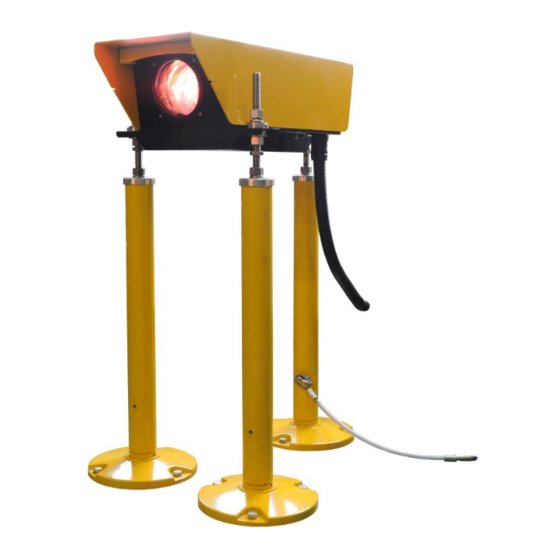
Advanced Airport Lighting System
Precision Approach Path Indicator
PAPI-LED-066 / PAPI-LED-220
Operation Manual
Please read this manual carefully before construction, installation and operation of
the product.
Please keep this manual properly for further reference.
This manual is subject to change without prior notice.
Airsafe Airport Equipment Co., Ltd.
1
Advertisement
Table of Contents
Troubleshooting

Related Manuals for Airsafe PAPI-LED-066

Summary of Contents for Airsafe PAPI-LED-066
- Page 1 PAPI-LED-066 / PAPI-LED-220 Operation Manual Please read this manual carefully before construction, installation and operation of the product. Please keep this manual properly for further reference. This manual is subject to change without prior notice. Airsafe Airport Equipment Co., Ltd.
- Page 2 Advanced Airport Lighting System Revision Description Version Approved Description Revised by Date Z. H, First release V1.0 C. JQ Jun. 18, 2019 H. GT Modified 2.7, 3.1, 3.2 V1.1 Z. H C. SY Sep. 25, 2020 Add S-type installation method G.JH Modify 3.3.5 C.JQ...
-
Page 3: Table Of Contents
Advanced Airport Lighting System Table of Content 1.0 Foreword ............................5 1.1 Illustrations and Meanings ....................6 1.2 Safety Rules and Notices ...................... 7 1.3 Quality Assurance and Responsibility ................... 8 2.0 Introduction ........................... 9 2.1 Technical Specifications ...................... 10 2.2 Application Environment .................... - Page 4 Advanced Airport Lighting System 6.1.4 Inspection Method of Transverse Horizontal Angle ..........66 6.2 Troubleshooting of Common Faults ..................69 7.0 List of Components and Ordering of Spare Parts and Accessories ..........70 8.0 Conversion Table ........................72 9.0 Packaging, Transportation and Storage ..................73 9.1 Packaging and Weight ......................
-
Page 5: Foreword
Advanced Airport Lighting System 1.0 Foreword ICAO Airport Service Manual Part 9 “Airport Maintenance Practices” and FAA AC150/5345-26 Maintenance of Airport Visual Aid Facilities are the highest criterions for site installation and maintenance of such lighting fixtures. This manual was compiled with considerable reference to these two criterions. -
Page 6: Illustrations And Meanings
Advanced Airport Lighting System 1.1 Illustrations and Meanings ○ Following illustrations will appear in this manual where necessary to remind or warn construction or maintenance personnel. ○ Please continue reading the subsequent content of this manual after properly understanding the meanings of these illustrations. ... -
Page 7: Safety Rules And Notices
Advanced Airport Lighting System 1.2 Safety Rules and Notices Using the light fixtures outside of airport is strictly prohibited. ※ Inadequate maintenance or casual touch will cause light faults. Be careful when handling the precision approach path indicator. ※... -
Page 8: Quality Assurance And Responsibility
Advanced Airport Lighting System 1.3 Quality Assurance and Responsibility Any defect in design, material or workmanship, which may occur during proper and normal use over a period of one year from date of installation but less than 15 months from date of shipment, or within the warranty period of the tender, will be repaired or preplaced by manufacturer free of charge. -
Page 9: Introduction
Advanced Airport Lighting System 2.0 Introduction ○ Introduction and application The PAPI system shall consist of a wing bar of four sharp transition multi-lamp (or paired single lamp) units equally spaced. The system shall be located on the left side of the runway unless it is physically impracticable to do so. ○... -
Page 10: Technical Specifications
Advanced Airport Lighting System 2.1 Technical Specifications This product conforms to the provisions of the following standards or technical specifications. For dated standards or technical specifications, only the edition cited applies. For undated references, the latest edition of the referenced document (including any amendments) applies. -
Page 11: Technical Parameters
2.4 Technical Parameters Precision approach Precision approach Name path indicator (066) path indicator(220) Type PAPI-LED-066 PAPI-LED-220 Inside the light box: ambient temperature > 55 ℃, ambient Environmental humidity < 45% conditions 1 Power / remarks 58W/normal operation Inside the light box: ambient temperature <... - Page 12 Advanced Airport Lighting System modules work simultaneously ≥100000h (L70) Light source life...
-
Page 13: Technical Features
Advanced Airport Lighting System 2.5 Technical Features • Light distribution and color of the lighting fixtures meet the requirements of Attachment 14 of ICAO & FAA AC 5345-28. • Excellent optical system design makes excellent red and white transition of PAPI with straight transition line. - Page 14 Advanced Airport Lighting System • Three leg type horizontal support and height adjustment structure for convenient and accurate on-site installation and adjustment. • Equipped with independent level in horizontal and longitudinal direction for convenient installation and maintenance. • The maximum windward area of the lighting fixture is 0.48m². •...
-
Page 15: Structure
Advanced Airport Lighting System 2.6 Structure 2.6.1 Key Components of Upper Box Power supply 6.6A Power supply 220V Common parts of power supply 6.6A and 220V: Spare parts of 6.6A 1. Upper cover plate assy. 12. Hose connector power supply: 2. -
Page 16: Key Components Of Landing Leg Assy
Advanced Airport Lighting System 2.6.2 Key Components of Landing Leg Assy 1. Flange 2. Landing leg 3. Front cover of landing leg 4. Tapping screw ST5.5 5. Spring washer 16 6. Screw stem 7. Hex nut M16 8. Hex thin nut M16 9. -
Page 17: Interpretation Of System Terminology
Advanced Airport Lighting System 2.7 Interpretation of System Terminology 2.7.1 Elevation The beam centers of all lighting fixtures in the PAPI system aim at the approach slope according to the defined subtle deviation and the elevation means the included angle of the beam center of the lighting fixtures and the horizontal plane. 2.7.2 Key Buttons and Plug-ins The general framework of the PAPI control panel is shown in Figure below and definitions of the key buttons and plug-ins are as follows:... - Page 18 Advanced Airport Lighting System SW2 and set the system to Factory Setup Status when setting CAN address or replacing the control plate. The PAPI system has four lamps, each with a different address, which can be configured as 1, 2, 3, 4, 5, 6, 7, 8. The eight addresses are divided into two groups, 1, 2, 3, 4 as one group and 5, 6, 7, 8 as the other group.
- Page 19 Advanced Airport Lighting System Display under “Store” Display under “Error”...
-
Page 20: Two Working Conditions And Four Modes
Advanced Airport Lighting System 2.7.3 Two Working Conditions and Four Modes This PAPI system has two working conditions and four modes, whose relations are shown in Figure below: 工厂设置 Factory 状态 Mode Press SW1 for 5 当SW2地址为9 times within the SW2地址不为9 的前2秒内SW1 SW2 Address is not 9... - Page 21 Advanced Airport Lighting System under the “Operation Mode” every 3 seconds, and the stored angle is displayed under the “Store Mode” every 2 seconds. When the system is abnormal, the “Operation Mode” changes to the “Error Mode”. (1) “Factory Mode”: When PAPI is under “Factory Mode”, the digital tube only displays the current angle.
- Page 22 Advanced Airport Lighting System off the light to ensure the normal flight calibration or maintenance work. The display method of the four-digit digital tube is 4 characters initiated by letter C (the digital tube displays “C+ value of the current elevation”), with the display shown in Figure below: Display under “Calibrate Flight”...
- Page 23 Advanced Airport Lighting System Under this mode, the angle displayed by the digital tube is immediate. When the real angle of PAPI has any subtle change, the angle of the digital tube will change accordingly. PAPI must be set to “Operation Mode” for work. ※...
- Page 24 Advanced Airport Lighting System Display within 2s Display within 3s These two data are displayed alternately under “Operation Mode”. Take the above-mentioned figures as an example, although the difference between the current operating angle and the current stored angle is 0.08° , it is still within the allowable range and PAPI will not have any action.
- Page 25 Advanced Airport Lighting System tube will display 4 characters initiated by letter E (the digital tube displays “E+ currently stored angle value”): Display under “Error Mode” when there is an angle deviation The above-mentioned digital tube information displays “Error Mode” and the current angle is 3.58.
-
Page 26: Power Supply Of Papi
Advanced Airport Lighting System 2.7.4 Power Supply of PAPI PAPI-LED-066 is powered by a constant current regulator. PAPI-LED-220 is powered by 220 V AC and dimmed by monitoring the light intensity of the external environment through the light control panel. When the external ambient light intensity is above 600Lux, the lamp enters the day mode;... - Page 27 Advanced Airport Lighting System Low Light Intensity High Light Intensity...
-
Page 28: Installation Of Lighting Fixtures
Advanced Airport Lighting System 3.0 Installation of Lighting Fixtures From the view of the runway threshold, the PAPI system shall be set on the left of the runway, unless it is impracticable according to the actual situation. The PAPI system must consist of four lighting fixture units with equal distance. 3.1 Location of PAPI system The distance between the inside edge of the PAPI lighting fixture unit closest to the runway and the runway edge shall be 15m (±... -
Page 29: Boundary Dimension
Advanced Airport Lighting System Runway Typical PAPI unit Layout (Figure 3-3) Note: D1 means the distance between the runway threshold and central location of the PAPI lighting fixtures. 3.2 Boundary Dimension The maximum installation height of the lighting fixtures is 900mm and the dimension of the corresponding luminous center is 814mm. -
Page 30: On-Site Installation Of Papi Lighting Fixtures
Advanced Airport Lighting System Figure 3-4 Overall dimensions of installation mode S Figure 3-5 Overall dimensions of installation mode P In any case, the maximum installation height of PAPI shall not exceed 1m ※ Meet the standard requirements 3.3 On-site Installation of PAPI Lighting Fixtures In order to ensure the operating stability of the PAPI system, the manufacturer suggests that the PAPI lighting fixtures should be installed on a prefabricated cement foundation. - Page 31 Advanced Airport Lighting System Concrete foundation Contraction Incoming with rebar keel Anti-lawn joint pipe Isolation transformer box Flange Lighting Threading pipe fixture Figure 3-6 on-site installation dimension of mode S...
- Page 32 Advanced Airport Lighting System Concrete Incoming Contraction foundation with pipe Anti-lawn joint rebar keel Isolation transformer box Flange 240 Threading pipe Lighting fixture Figure 3-7 on-site installation dimension of mode P Make sure that the luminous channel is not blocked by weeds after installation ※...
-
Page 33: Flange Fixation
Advanced Airport Lighting System 3.3.1 Flange Fixation In order to ensure that the lighting fixtures are installed firmly and reliably, the manufacturer suggests using the method to embed the foundation bolt in the prefabricated base. It is suggested to use the stainless steel M10 foundation bolt (with the length of greater than 150mm), as shown in Figure 3-8. - Page 34 Advanced Airport Lighting System installation plate of installation method S Figure 3-9 Lamp center Light output center E plane is the used criterion Figure 3-10 installation plate of installation method P When it is impracticable to embed the foundation blot in the cement foundation, the stainless steel expansion bolt may be used, with the bolt dimension of no less than M10×...
- Page 35 Advanced Airport Lighting System The manufacturer does not recommend the use of expansion bolt fixation. Although this method is convenient for construction, if the construction is not in place, there is a risk of loose fixation. The fixation method with the expansion bolt shall be avoided. ※...
-
Page 36: Installation Of Legs
Advanced Airport Lighting System 3.3.2 Installation of Legs First, put three flanges into the embedded foundation bolt and fix them with nuts. According to the height design requirements of PAPI and on-site actual situation, determine the length of the extension pole of the PAPI lighting fixtures. Please note that the lengths of the extension pole of four lighting fixtures are inconsistent. - Page 37 Advanced Airport Lighting System Screw the adjusting screw with nut into the end cover thread on the extension pole. Please note that the adjusting screw protrudes about 190mm from the landing leg and tighten the M16 hex nuts of the end cover of the landing leg and lower end of the screw to make it fixed.
-
Page 38: Same Height Setting Of Lighting Fixtures
Advanced Airport Lighting System 3.3.3 Same Height Setting of Lighting Fixtures When the PAPI lighting fixture system is installed, it must be ensured that the beam centers of four luminous units are on the same level while ensuring that the height of the beam center of the PAPI system meets the design requirements. - Page 39 Advanced Airport Lighting System (see Figure 3-8) to make the bubble of the horizontal bubble level indicators of all lighting fixtures in the middle. If PAPI box is always basically in a horizontal state, the height adjustment of PAPI can be more accurate. By adjusting the M16 hexagon nut behind PAPI, the elevation angle of PAPI can be adjusted.
- Page 40 Advanced Airport Lighting System Unless it is necessary, keep the upper cover in a closed state during installation ※ The on-site dust may impact the optical system in PAPI. Touching the optical components with naked or dirty hands is strictly prohibited ※...
-
Page 41: System Matched Power/Communication Cable Selection
Advanced Airport Lighting System 3.3.4 System matched power/communication cable selection Communication Cable: In order to avoid impacts of the external interference, the cable used to transmit data must be twisted pair with shielding layer and the shielding layer shall be connected to the reference ground. - Page 42 Advanced Airport Lighting System Serial No. Description Rules There must be two terminal resistances of 118Ω<RT<130Ω at both network ends (between signals CAN_L and CAN_H)! The reference potential “CAN_GND” is connected to the ground (PE) at a certain point. There must be one-point grounding! When the cable with double shielded layers, the external shielded layer is connected to the ground at a certain point.
-
Page 43: Electrical Wiring Of Lighting Fixtures
Advanced Airport Lighting System 3.3.5 Electrical Wiring of Lighting Fixtures PAPI system is consisted of four lighting units. The control between the units is realized by bus. The red bus is positive, and the black bus is negative. It must not be reversed. - Page 44 Advanced Airport Lighting System Circuit Circuit Circuit 电路板 Circuit 电路板 电路板 电路板 board board board board 6.6A 接线排 220V Terminal Block CANH CANL Monitoring 监控 PAPI 系统 网关 System RS485 PAPI-LED-R 总体接线图 Overall Wiring Diagram of PAPI-LED-R Diagram of PAPI Gateway Terminal Connect CAN bus and gateway correctly.
- Page 45 Advanced Airport Lighting System Address knob 120Ω resistance Wiring requirements: The maximum cable applicable to the terminal block is 4mm , and the recommended cable is 2mm Insert the cable into the copper pipe, crimp the copper pipe according to the following steps, and then insert it into the socket of the wiring block.
- Page 46 Advanced Airport Lighting System 1. Prepare the copper tube and peel off the cable skin by 5-10mm. 2. Insert one end of the stripped wire into the copper pipe and crimp it. 3. After the crimping is completed, confirm that it is firm, and the effect is as shown in the figure.
-
Page 47: Adjustment And Setting Of Lighting Fixture Elevation
Advanced Airport Lighting System 3.3.6 Adjustment and Setting of Lighting Fixture Elevation Four PAPI units placed on site have different elevations respectively. Therefore, elevation setting is an important step for installing the PAPI lighting fixture units. The correct elevation ensures that the PAPI system works. According to the provisions, the unit with the greatest elevation in the PAPI system shall be at the position close to the runway and that with the lowest elevation in the PAPI system shall be on the most outside which is the farthest from the runway. - Page 48 Advanced Airport Lighting System Angle display Figure 3-19 Because the elevation display by the digital tube on the control panel is a decimal degree, while the designed elevation is often a degree of degree-minute system, the fractional part of the designed elevation shall be converted into the decimal degree value prior to adjustment.
- Page 49 Advanced Airport Lighting System Repeat the above-mentioned steps until the elevation setting of four PAPIs is completed. After adjustment and setting of 4 lighting fixtures are completed, the on-site installation of the PAPI system is basically completed. Reconfirm whether the bubble of the level angle instrument is in the middle and the angle displayed by the digital tube is equal to the designed elevation.
-
Page 50: Flight Calibration Inspection And Adjustment Of Lighting Fixtures
Advanced Airport Lighting System 4.0 Flight Calibration Inspection and Adjustment of Lighting Fixtures Before the PAPI system is formally put into use, flight calibration must be performed. The airport may independently perform the flight calibration for the PAPI system, or arrange it with that of the airport runway at the same time. During flight calibration, making sure that the electrical control of all lighting fixture units is in “Calibrate Flight”. -
Page 51: Disposal After Flight Calibration
Advanced Airport Lighting System During flight calibration, adjustment of the M16 nut must be very slight. ※ Casual amplitude adjustment may cause repetitive work. The flight calibration of PAPI is usually completed once. If the pilot thinks it is necessary, the secondary flight may be performed. - Page 52 Advanced Airport Lighting System After the angle is stored, release the button, the digital tube recovers its display: “C+ current elevation value”, namely, “Calibrate Flight”. Repress the button to make the mode to be switch to “Operation” and the digital tube will alternately display “A+ current elevation value”...
- Page 53 Advanced Airport Lighting System (3) Label recording A blank label is pasted on the longitudinal indictor rack of the PAPI lighting fixtures for recording the angle after actual flight calibration of the PAPI unit. After flight calibration, the actual elevation of the lighting fixtures could be recorded on the label paper posted on the longitudinal indicator rack with an oily marking pen for reference.
-
Page 54: Replacement Of Components Of Lighting Fixtures
Advanced Airport Lighting System 5.0 Replacement of Components of Lighting Fixtures When any damage or failure occurs to any consumable or other component of the lighting fixtures, it is required to timely dismantle the lighting fixtures for replacement of the component. Replacement of components needs to dismount the lighting fixtures, so any minor error will cause adverse consequences. -
Page 55: How To Replace Light Source Assembly
Advanced Airport Lighting System 5.1 How to Replace Light Source Assembly If the LED chips in a PAPI fails to work and the light output is lower than normal brightness level during daily inspection and maintenance, the user shall immediately replace the light source. - Page 56 Advanced Airport Lighting System Loosen two screws Tighten two screws During installation, making sure that the power supply is disconnected. ※ Otherwise it may cause electric leakage or shock. Touching the optical lens directly without gloves is strictly prohibited.
-
Page 57: How To Replace Main Control Board
Advanced Airport Lighting System 5.2 How to Replace Main Control Board Before replacing the control board, make sure that the power supply is off. Turn off the power before replacing the control board. ※ If the isolation transformer is open circuit, electric shock may occur. -
Page 58: How To Replace Digital Display Panel
Advanced Airport Lighting System During installation, make sure that the power supply is disconnected. ※ Otherwise it may cause electric leakage or shock. 5.3 How to Replace Digital Display Panel Before replacing the digital display panel, confirm and record the current accurate angle. - Page 59 Advanced Airport Lighting System enter "factory setting state". 3. After the digital tube displays "0.00", press SW1 continuously, and the angle will increase by 0.01 ° for each press. 4. Long press SW1 for more than 1 second, and the angle will increase at the speed of 0.2 °...
-
Page 60: Replace Terminal Block
Advanced Airport Lighting System 5.4 Replace Terminal Block If the connector is burnt out due to failure, replace it according to the following steps. 1. Use a slotted screwdriver 3.5 × 100, press the orange switch and pull all cable terminals out of the terminal block. -
Page 61: Maintenance Of Precision Approach Path Indicator
Advanced Airport Lighting System 6.0 Maintenance of Precision Approach Path Indicator 6.1 Daily Inspection and Maintenance Maintenance of the lighting fixtures shall comply with the “Airport Maintenance Practice” of Section 9 of ICAO’s Airport Service Manual and FAA’s AC150/5345-26 Maintenance of Visual Navaids at Airport. Because the PAPI system is a very precision optical system, the daily maintenance must be performed by the professional. - Page 62 Advanced Airport Lighting System Make sure that the light intensity of PAPI and the boundary between red and white is clear ※ Otherwise it may cause incorrect judgment of the pilot. 3. Inspection of PAPI fixation. Check that all the adjusting nuts on the landing leg are locked and the chassis connection is reliable.
-
Page 63: Troubleshooting Of Common Error Of Control Board
Advanced Airport Lighting System 6.1.2 Troubleshooting of Common Error of Control Board Under “Operation”, when the elevation of any unit in the PAPI system is greater than the set limit or all lamps are damaged, this unit will enter “Error” and the digital tube will display the “E+ decimal system value of the current elevation”, as shown in figure below: Displays under two “Error”... - Page 64 Advanced Airport Lighting System Under “Operation”, when the light source in any unit of the PAPI system is damaged, the digital tube of the unit with damaged lamps will enter “Error Mode”, and transmit the signal to other PAPI units through the BUS, make the whole PAPI system to turn off the light and the monitoring module alarms.
-
Page 65: Inspection Method Of Elevation
Advanced Airport Lighting System 6.1.3 Inspection Method of Elevation Visually inspect the angle displayed by the digital tube on the control panel to confirm that the displayed angle is within the allowable deviation range of the elevation of this lighting fixture. At this moment, bubbles of the horizontal and vertical level indicator systems shall be in the middle. -
Page 66: Inspection Method Of Transverse Horizontal Angle
Advanced Airport Lighting System 6.1.4 Inspection Method of Transverse Horizontal Angle The digital display tube in PAPI only displays the longitudinal horizontal angle, and the transverse horizontal angle is generally simply identified and verified by only one blister. It is necessary to open the upper cover of the lamp, and the process is cumbersome. - Page 67 Advanced Airport Lighting System When the transverse horizontal angle is within ± 0.05 ° , the indicator displays as follows: When the transverse horizontal angle is within ± 0.2-3 ° , the indicator displays as follows:...
- Page 68 Advanced Airport Lighting System When the transverse horizontal angle exceeds ± 0.4 ° , the indicator displays as follows: The on and off of the transverse horizontal angle indicator is identified and controlled by the angle sensor. As the angle sensor is an electronic product, if the seasonal change or the temperature difference between day and night is huge, it may cause slight changes in the on and off of the indicator, which is a normal phenomenon and can be ignored, which will not affect the normal operation of the system.
-
Page 69: Troubleshooting Of Common Faults
Advanced Airport Lighting System 6.2 Troubleshooting of Common Faults Common Fault Causes Troubleshooting Methods Faults 1. Light source damage 2. Wrong wire connection 1. Replace the lamp Loose wire connector of light source 2. Correctly and reliably connect CAN bus off Abnormal CAN bus address the circuit 3. -
Page 70: List Of Components And Ordering Of Spare Parts And Accessories
Advanced Airport Lighting System 7.0 List of Components and Ordering of Spare Parts and Accessories The list of parts of this product and relevant ordering information of the spare parts and accessories are shown in the Table of this Chapter. The manufacturer accepts to order in a manner of component or separate ordering of the parts. - Page 71 Advanced Airport Lighting System List of components and spare parts of landing leg assembly: Structure No. Component Name Order No. Remarks Flange 276A1 Landing leg 46322 Front cover of landing leg 46317 Tapping screw ST5.5 GB/T845 ST5.5× 19 Spring washer 16 GB/T7244 Screw stem 61101...
-
Page 72: Conversion Table
Advanced Airport Lighting System 8.0 Conversion Table 〃 〃 1° = 60 = 0.016° Decimal degree Minute Decimal degree Minute Decimal degree Minute 0.017 0.350 0.683 0.033 0.367 0.700 0.050 0.383 0.717 0.067 0.400 0.733 0.083 0.417 0.750 0.100 0.433 0.767 0.117 0.450... -
Page 73: Packaging, Transportation And Storage
Advanced Airport Lighting System 9.0 Packaging, Transportation and Storage 9.1 Packaging and Weight Packaging of upper box: 1 pc / box Gross weight of upper box: 35 KG / box Volume of upper box: 780× 580× 280 mm³ Packaging of landing leg: 12 pcs / box (including flange) Gross weight of landing leg: 40KG/ box (including flange) Volume of landing leg: 835×... - Page 74 Advanced Airport Lighting System The final right to interpret this manual is reserved by Airsafe Airport Equipment Co., Ltd. Thanks for your purchasing and using AIRSAFE product! Address: No. 205, Changchuan Road, Baoshan District, Shanghai, China Postal Code: 200949 Tel.: +86 (0)21 6307 3484...
Need help?
Do you have a question about the PAPI-LED-066 and is the answer not in the manual?
Questions and answers