Table of Contents
Advertisement
Quick Links
"Graphics and specifications may change without notice".
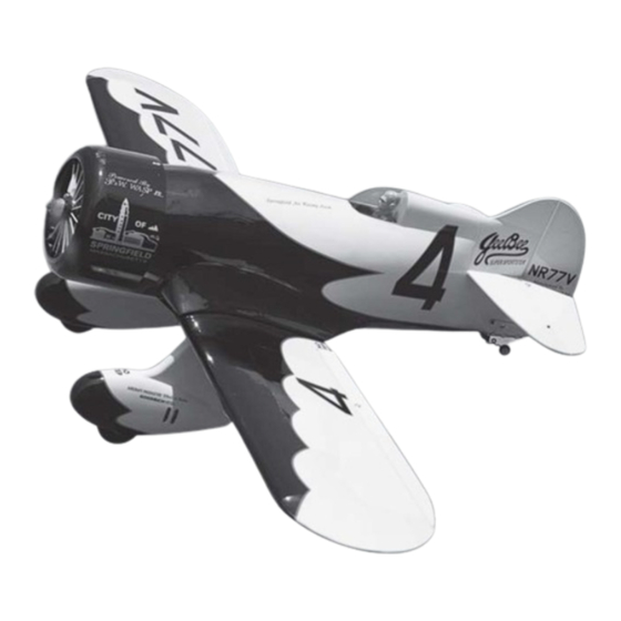
Specifications
Wing span-------------------------------------- 70.9 in------------------------------ 180cm.
Wing area------------------------------------- 863.4 sq.in------------------- 55.7 sq.dm.
Approximate flying weight------------------10.6 lbs------------------------------4.8kg.
Length------------------------------------------ 46.6in -----------------------------118.3cm.
Recommended engine size-------------- .1.20 cu.in----------------------- 2-stroke.
Radio System required 4 channels with 6 servos
Flying skill level Intermediate/advanced.
Kit features.
•
Ready-made—minimal assembly & finishing required.
•
Ready-covered covering.
•
Photo-illustrated step-by-step Assembly Manual.
Made in Vietnam.
ASSEMBLY MANUAL
.1.50cu.in------------------------4-stroke.
MS: SEA 82
Advertisement
Table of Contents

Related Manuals for GEEBEE SEA 82

Summary of Contents for GEEBEE SEA 82
- Page 1 MS: SEA 82 ASSEMBLY MANUAL “Graphics and specifications may change without notice”. Specifications Wing span-------------------------------------- 70.9 in------------------------------ 180cm. Wing area------------------------------------- 863.4 sq.in------------------- 55.7 sq.dm. Approximate flying weight------------------10.6 lbs------------------------------4.8kg. Length------------------------------------------ 46.6in -----------------------------118.3cm. Recommended engine size-------------- .1.20 cu.in----------------------- 2-stroke. .1.50cu.in------------------------4-stroke. Radio System required 4 channels with 6 servos Flying skill level Intermediate/advanced.
-
Page 2: Fuselage Assembly
. Flying the GEEBEE is simply a joy. This instruction manual is designed to help you build a great flying aeroplane. Please read this manual thoroughly before starting assembly of your GEEBEE. Use the parts listing below to identify all parts. -
Page 3: Hinging The Ailerons
This will ensure proper assembly as the GEEBEE is made from natural materials and minor adjustments may have to be made. The paint and plastic parts used in this kit are fuel proof. -
Page 4: Hinging The Elevator
Instruction Manual GEEBEE. 7) Repeat this process with the other wing HINGING THE ELEVATOR. panel, securely hinging the aileron in place. 8) After both ailerons are securely hinged, Glue the elevator hinges in place using the firmly grasp the wing panel and aileron to same techniques used to hinge the ailerons. -
Page 5: Rudder Control Horn
CONTROL HORN CONTROL HORN M3 M3 SCREW Aluminum Washer Epoxy. Epoxy ALUMINUM WASHER Wing Aluminum Washer M3 LOCK NUT M3 LOCK ALUMINUM WASHER Epoxy. Horizontal Stabilizer. Wing 16mm 16mm Epoxy. Elevator control horn. RUDDER CONTROL HORN. Rudder control horn: ELEVATOR CONTROL HORN. Using the same techniques used aileron control horn. -
Page 6: Engine Mount Installation
Instruction Manual GEEBEE. CONTROL HORN M3 SCREW ALUMINUM WASHER EPOXY. ALUMINUM WASHER M3 LOCK NUT EPOXY. Rudder Fuselage 16mm Rudder control horn. Hinge. ENGINE MOUNT INSTALLATION. See pictures below.Make yourself the M3x15mm. template of your engine on paper. 3x15mm. -
Page 7: Installing The Stopper Assembly
Mark and drill 4 holes for engine mount. 4x30mm. Insert 4 blind nuts to firewall. Thread locker glue. Please choose one of the positions below to suit your motor, then you drill with a 2mm diameter drill then and next you drill again with a 5.5mm drill to install the Blind Belt / Belt BILLION . -
Page 8: Fuel Tank Installation
Instruction Manual GEEBEE. FUEL TANK INSTALLATION. You should mark which tube is the vent and which is the fuel pickup when you attach fuel tubing to the tubes in the stopper. Once the tank is installed inside the fuselage, it may be difficult to determine which is which. -
Page 9: Installing The Battery
2) Place your engine onto the engine INSTALLING THE BATTERY. mount. Adjust the engine is centered of the edges of the engine case. 3) When you are satisfied with the align- Battery tray. ment, mark the locations of the engine mounting. - Page 10 Instruction Manual GEEBEE. 2) While keeping the back edge of the Dummy cowl flush with the marks, align the front of Engine the cowl with the crankshaft of the engine. The front of the cowl should be positioned so the crankshaft is in nearly the middle of the cowl opening.
- Page 11 ELECTRIC POWER CONVERSION. Locate the items neccessary to install the electric power conversion included with your model. - Motor: 1100 - 2000 Watts - Propeller: 17x8 ~ 19x10 - ESC: 85A - 8S- 10S Lipo Attach the electric motor box to the firewall centered with the cross lines drawn on the electric motor box and fire Please drill into the crosshair to connect...
- Page 12 Instruction Manual GEEBEE. Attach the motor mount to the front of the electric motor box using four 4mm blind nut, four M4x20mm hex head bolts to se- cure the motor. Please see picture shown. Blind nut. Attach the motor to the front of the...
-
Page 13: Installing The Spinner
Balsa stick. Epoxy. Attach the speed control to the side of the motor box using two-sided tape and tie wraps. Connect the appropriate leads from the speed control to the motor. Make sure the leads will not interfere with the operation of the motor. -
Page 14: Installing The Switch
Instruction Manual GEEBEE. Switch. THROTTLE SERVO ARM INSTALLATION. INSTALLING THE FUSELAGE SERVO. Install adjustable servo connector in the servo arm . Because the size of servos differ, you Loctite secure. may need to adjust the size of the precut open- ing in the mount. - Page 15 Installing the aileron servo in place using the same techniques used to flap servo. Small weight. String. Wing rib. Wing. Small Weight. Small Weight. String. String. Attach the string to the servo lead and carefully thread it though the wing. AILERON PUSHROD HORN INSTALLATION.
-
Page 16: Wing Assembly
Instruction Manual GEEBEE. Wing Wing Aileron Aileron M2 lock nut. Epoxy. Aileron. Wing. 2) Remove the brace when satisfied with its fit ineach wing half. Coat the dihedral brace with 30 minute epoxy. Next, pour some epoxy Repeat the procedure for the other wing. -
Page 17: Installing The Horizontal Stabilizer
Masking tape. Pen. 3) Peel off the backing from the self adhe- sive covering strip. Apply the strip to the centre section of the wing starting from the bottom trailing edge. Wrap the strip all the way around the wing until it meets the trailing edge again. Trim off any excess strip. - Page 18 Instruction Manual GEEBEE. Put the vertical stabilizer into the in the top of the horizontal fin. The bottom edge of the stabilizer should also be firmly pushed against the top of the horizontal stabilizer. Vertical Stabilizer. Horizontal 90º Stabilizer. INSTALLING THE VERTICAL STABILIZER.
-
Page 19: Installing The Main Gear Wires
INSTALLING THE MAIN GEAR WIRES. Remove the covering. Wing botom. - Page 20 guide, mark the locations of the four 3 x 15mm...
- Page 21 Set of fibreglass wheel pants. Install fibre glass wheel pants.
- Page 23 Screw the wheel pants. Drill diameter =12mm. Screw M3x10mm. 11mm. 9mm. Install wheel to the landing gear.
- Page 24 Instruction Manual GEEBEE. = 35cm = 50cm Calbe trust. Fix cable to the bottom wing.
- Page 25 ELEVATOR- RUDDER PUSHROD HORN INSTALLATION. 1) Elevator and rudder pushrods assembly follow pictures below. Elevator control horn. Rudder control horn.
- Page 26 Instruction Manual GEEBEE. M2 clevis. M2 Lock nut. Attach to servo arm in fuselage. Attach to elevator - rudder control horn. Elevator. Rudder. Elevator. 2) Connect the elevator and rudder servos to your radio’s receiver and turn on the sys- Metal clevis.
-
Page 27: Wing Fillet Installation
4) Install servos arm to servos. Notice the position of the servo arms on the servos. See picture below. 3 x 12mm diametter. MOUNTING THE CONTROL CLASP. WING FILLET INSTALLATION. See pictures below: Trim and cut. Pen. Machine Screw 2 MM x 20 MM. Control clasp. - Page 28 Instruction Manual GEEBEE. C/A glue. INSTALLATION PILOT AND CANOPY. C/A glue. INSTALLING THE BATTERY-RECEIVER. 1) Plug the six servo leads and the switch lead into the receiver. Plug the battery pack lead into the switch also. 2) Wrap the receiver and battery pack in the protective foam rubber to protect them from vibration.
- Page 29 NSTALLATION FUSELAGE HACTH. Please see Images below: 2x6mm.
- Page 30 Instruction Manual GEEBEE. 20mm. 3x15mm.
- Page 31 ATTACHMENT WING - FUSELAGE. Bolt the wing to fuselage. Epoxy. BALANCING. 1) It is critical that your airplane be bal- anced correctly. Improper balance will cause your plane to lose control and crash. The cen- ter of gravity is locate back from the lead- Trim and cut.
-
Page 32: Control Throws
Instruction Manual GEEBEE. CONTROL THROWS. 1) We highly recommend setting up the GEEBEE using the control throws listed at right. We have listed control throws for both Low Rate (initial test flying/sport flying) and High Rate (aerobatic flying). 2) Turn on the radio system, and with the... -
Page 33: Flight Preparation
2) Check every bolt and every glue joint Do not use the aerobatic settings for in the GEEBEE to ensure that everything is initial test flying or sport flying. tight and well bonded. 4) By moving the position of the adjust-...
Need help?
Do you have a question about the SEA 82 and is the answer not in the manual?
Questions and answers