Advertisement
Quick Links
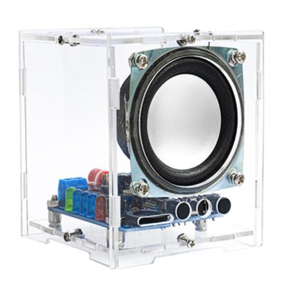
ICStation Bluetooth Audio Amplifier Electronic Kit
1. Description:
The sound quality of this Bluetooth kit is excellent and it comes with sound spectrum
rhythm lights, making it a truly unique and fun product. Perfect for home, school or
hobbyists for soldering practice.
2.Parameter:
1>.Work Voltage:DC 5V
2>.Work Temperature:-25℃~85℃
3>.PCB Board Size:65x49mm
4>.Shell Size:70x70x80mm
5>.Speaker Power:4ohm 3W
3.Circuit and
Diagram:
1
https://www.icstation.com/
Advertisement

Subscribe to Our Youtube Channel
Related Manuals for ICStation GY20971-1


Summary of Contents for ICStation GY20971-1
- Page 1 ICStation Bluetooth Audio Amplifier Electronic Kit https://www.icstation.com/ 1. Description: The sound quality of this Bluetooth kit is excellent and it comes with sound spectrum rhythm lights, making it a truly unique and fun product. Perfect for home, school or hobbyists for soldering practice.
- Page 2 4.Components Layout...
- Page 3 5.Components List: 6. Installation Steps: Step1: Install the 6pcs color ring resistor. 12K resistors at R1, R7; 330ohm at R3, 10K at R4, R5; 33K at R6. The resistors are regardless of direction. The color ring readings of the color ring resistors are shown in the figure below.
- Page 5 Step 2: Install SMD integrated circuit HT6872. Note: there is a small pit on the chip when installing, and the direction is consistent with the figure below Step 3: Install Ceramic/monolithic capacitors. Monolithic capacitors have no distinction between positive and negative poles.
- Page 6 Step 4: Install the Bluetooth module. Place the components of the Bluetooth module face up on the circuit board. Step 5: Install electrolytic capacitors at C2, C3, C4, C5, C6, C7. Note: The long leg of the electrolytic capacitor is the positive pole, and the short leg is the negative pole.
- Page 7 Step 6: Install blue and white adjustable resistors. The blue and white adjustable resistor RP2 is used to control the display range of the LED volume column.
- Page 8 Step 7:Install IC KA2284 KA2822 is an LED volume level indicator circuit. Facing the KA2284, there is a literal, the leftmost pin is the first pin, and at the installation position of the circuit board, the side with the square pad on the side is connected to the first pin (as shown in below picture).
- Page 9 Step 9: Install the 3F07 audio stand. The audio socket is used as the audio signal input port. When the Bluetooth signal is not connected, the audio signal can be input from the following port to make the speaker sound. Step 10: Install the Dial Potentiometer.
- Page 10 Step 11: Installing the key switch. Key switch for power switch Step 12: Install Tact Switch The touch switch is used for Bluetooth module functions, such as volume, song selection and other functions...
- Page 11 Step 13: Install 2P Terminal Blocks. The opening of the wiring terminal is outward, and the wiring terminal marked with +5V and GND is connected to the power supply, the positive pole of the power supply is connected to the position of +5V, and the negative pole of the power supply is connected to GND.
- Page 12 Step 14: Install the shell 1. Use M3*6 screws to fix 4 one-way posts on the bottom plate 2. Install the key caps for the key switch and tact switch...
- Page 13 3.Fix the circuit board to the copper post with M3 nuts. 4. Use 4pcs M3 screws and nuts to fix the speaker to the shell...
- Page 14 5. Connect the speaker wire and the circuit board with a wire. 6. Connect the power cord. Cut off the DC head, if you have a USB power cable without DC, the please ignore the picture below.
- Page 16 7. Combined speaker shell 8. After 2 seconds when the power is turned on, the LED on the Bluetooth module will start to flash, and the name of the Bluetooth module displayed on the mobile phone is "MH‐M18", click to connect directly (without a password).
Need help?
Do you have a question about the GY20971-1 and is the answer not in the manual?
Questions and answers