Table of Contents
Advertisement
Quick Links
*911031-00*
911031-00
Wiring and Configuration
The Von Duprin DE5300 is designed for controlled egress applications when used in conjunction with a magnetic lock. It meets both life
safety and security needs, as well as the requirements of NFPA101 for "Special Locking Arrangement" and IBC "Special Egress-Control
Devices". All control inputs, auxiliary locking, local alarm and remote signaling outputs are self-contained in the DE5300 assembly.
Numerous field configurable options allow the device to be customized for the specific code or application requirements. The standard
DE5300 sounds an alarm and keeps the door secured for 15 seconds following an exit attempt with immediate release upon fire.
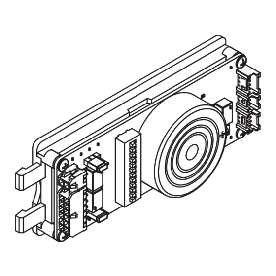
Control Box
#6-32 X 3/8" Faceplate Screws (4)
Basic Features........................................................................... 2
Installation Components ............................................................ 3
Electrical Specifications ............................................................. 4
Typical Wiring Diagrams ............................................................ 4
Single Door ............................................................................ 4
Double Door .......................................................................... 5
Electrical Trim ........................................................................ 7
Retrofit Wiring.............................................................................7
•
Do not exceed rated specifications.
•
The DE5300 must be installed in accordance with these instructions by a qualified electrician.
•
Wiring and applications must be in accordance with all local codes and regulations.
Customer Service
1-877-671-7011 www.allegion.com/us
DE5300 Delayed
Egress System
Mounting Bracket
PUSH UNTIL ALARM SOUNDS
DOOR CAN BE OPENED
IN 15 SECONDS
Door Sign
General Information
Parts Included
Module
Field Wiring Cable
#6-32 X 1/4" Mounting Bracket Screws (2)
Table of Contents
Installation ................................................................................. 8
Basic Functional Test ............................................................... 11
Module Setup .......................................................................... 11
Onboard Switch Settings Table ............................................... 12
Advanced Function Test .......................................................... 13
Onboard Indicators .................................................................. 14
Troubleshooting ....................................................................... 15
WARNING
Key Switch
Faceplate
Device Wiring Cable
Installation Instructions
© Allegion 2021
Printed in U.S.A.
911031-00 Rev. 04/21-e
Advertisement
Table of Contents

Related Manuals for Von Duprin DE5300


Summary of Contents for Von Duprin DE5300
-
Page 1: Table Of Contents
General Information The Von Duprin DE5300 is designed for controlled egress applications when used in conjunction with a magnetic lock. It meets both life safety and security needs, as well as the requirements of NFPA101 for “Special Locking Arrangement” and IBC “Special Egress-Control Devices”. -
Page 2: Basic Features
Remote Alarm Maglock Nuisance Delay Fire Alarm When a DE5300 is located in a public area, it can be desirable to system limit false releases when the Push Pad is accidentally pushed. The interface Nuisance Delay is the brief time a Push Pad can be accidentally Internal pushed before the Release Delay sequence starts. -
Page 3: Installation Components
Door loop or electric hinge can also be used. Provides fire alarm status to Required Fire Alarm DE5300 so that it can release the (NC contacts) Multiple Fire Alarms can be used in series. maglock in case of fire alarm. -
Page 4: Electrical Specifications
Ground Not Used Not Used *Includes current from DE5300 only (does not include current from optional components such as Inhibit Device, Remote Alarm, or Trim Device) Typical Wiring Diagrams (Single Door) • The DE5300 is used as a controlled egress device with access control. -
Page 5: Double Door
Frame Side Door Side Von Duprin RXLC Exit Device Yellow (NC) Green (C) RXLC Cable Blue (NO) EPT2/10 1. The maglock MBS provides added security and is optional DPS* -If not used, connect the WHT and GRY wire of the Device Wiring Cable together. - Page 6 Frame Side Door Side Door 1 Von Duprin RXLC Exit Device Yellow (NC) Green (C) RXLC cable Blue (NO) EPT2/10 Frame Side Door Side Door 2 Von Duprin RXLC Exit Device Yellow (NC) Green (C) RXLC cable Blue (NO) EPT2/10...
-
Page 7: Electrical Trim
On the discontinued DE5101 device, the Door Position Switch, Card reader and Fire Alarm contacts were tied to the white SC wire. On the new DE5300 device, these contacts are wired to the red 24VDC wire (see wiring diagrams below). -
Page 8: Installation
Installation Install end cap bracket. Disconnect Power To avoid risk of shock, disconnect AC power from power supply before proceeding with this installation. If using battery backup option, unplug all four wires from battery terminals. If installed, remove end cap, cover plate and end cap bracket. - Page 9 Installation, continued Slide cover plate fully into place. Slide module into mounting bracket as shown until module snaps into place. Install end cap. Route device wiring cable over mounting bracket and make connections on module per wiring diagrams in Section 4. Remove backing from door sign and apply above exit device (door sign is in cardboard tube).
- Page 10 Installation, continued 7m Remove and discard cylinder plug from key switch Connect key switch cable and field wiring cable to assembly in faceplate. module. Remove Connect Key Switch Cable to Module and loop through strain relief feature. Connect Cylinder Field Wiring Cable Plug to Module Use 1...
-
Page 11: Basic Functional Test
2. Turn the Key Switch counter-clockwise to put the DE5300 into Disarmed/Reset Mode (Status Indicator is OFF). 3. Turn the Key Switch clockwise which causes the DE5300 to enter Rearm Delay Mode (Status Indicator is ON for 10 seconds - this time is adjustable). -
Page 12: Onboard Switch Settings Table
Rearm Time person to exit or enter without an alarm through an unlocked door. 30 (Infinite) DE5300 powers up into Disarmed Powerup Mode (unlocked If the DE5300 is Armed and with alarm sounding). there is a power outage, then upon power restoration, the DE5300 powers up into Armed Powerup Mode (locked). -
Page 13: Advanced Function Test
3. Turn the Key Switch clockwise to arm the DE5300. -If the Rearm Time onboard switch setting is ON (default = 10 seconds), the DE5300 will enter Rearm Delay Mode. After Rearm Delay Mode expires, the DE5300 will enter Armed Mode. -
Page 14: Onboard Indicators
Inhibit contacts open (Active) DE5300 not secure (Relay contact state depends on Secure Relay NO/NC jumper setting) DE5300 secure DE5300 not in alarm (Relay contact state depends on Alarm Relay NO/NC jumper setting) DE5300 in alarm condition Maglock is unlocked... -
Page 15: Troubleshooting
-To trigger delayed egress, push the Push Pad in. The DE5300 will sound an Internal Alarm (red Status Indicator is flashing fast). -At the end of the Release Delay, the maglock will unlock allowing exit. The Internal Alarm will continue until the DE5300 is reset with the Key Switch or Inhibit Input (if INH Reset onboard switch setting is ON). - Page 16 Trim is unlocked when it Install the correct trim type. Secure) is being used. should be locked. 1. Set DE5300 switch 12 to OFF (Step M996L shipped Fail Safe by 2. Set switch on M996L to FSE. M996L trim not operating as default.
Need help?
Do you have a question about the DE5300 and is the answer not in the manual?
Questions and answers
can i change 15 second delay to 30 second delay ?
The Von Duprin DE5300 is designed to keep the door secured for 15 seconds following an exit attempt, in compliance with NFPA101 and IBC requirements. The provided information does not specify whether the delay can be extended to 30 seconds.
This answer is automatically generated