Table of Contents
Advertisement
Advertisement
Table of Contents

Related Manuals for Kamada power KMDPJ24100

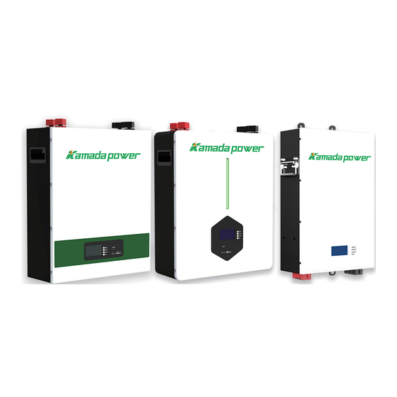
Summary of Contents for Kamada power KMDPJ24100
-
Page 2: Table Of Contents
Contents 1.ABOUT THIS MANUAL ......................................................1.1 Purpose ..............................1.2 Scope ..........................1.3 Safety Instructions ..2.INTRODUCTION ........................................................ 2.1 Features ..........................2.2 Product Over View ..........................2.3 Mounting the Unit ............................2.4 Specifications 3.INSTALLATION ....................................................3.1 Diagram of accessories ........................ -
Page 4: Introduction
2.INTRODUCTION The battery main using for energy storage system. Built-in smart BMS to match various of hybrid inverters. 2.1 Features LiFePO4 Battery. Long warranty period:5 years. Higher energy density, smaller volumn. This battery pack is designed for energy storage systems. Support connected in parallel mode for expansion. - Page 5 Name Function Description Power positive output, two terminals with the same Power Positive Terminal positive terminal is a parallel output 1.Testing battery performance RS485 Communication Interface 2.When multiple batteries are used in parallel, it acts as a communication connection port between batterie RS232 Communication Interface Testing and modifying battery parameters CAN Communication Interface...
- Page 6 (KMD-PC Series) 4321 ADD RST PARALLEL-RS485 RS232 CAN RS485...
- Page 7 Name Function Description Power positive output, two terminals with the same Power Positive Terminal positive terminal is a parallel output 1.Testing battery performance RS485 Communication Interface 2.When multiple batteries are used in parallel, it acts as a communication connection port between batterie RS232 Communication Interface Testing and modifying battery parameters CAN Communication Interface...
- Page 8 (KMD-PJ Series) RS485 RS232 PARALLEL-RS485 4321 RUN ALM 9 10...
- Page 9 Name Function Description Power positive output, two terminals with the same Power Positive Terminal positive terminal is a parallel output ON/OFF Indicator The indicator light is on to indicate that the battery is on 1. You can turn on and off the battery, the default is automatically turned on when the power switch is turned on, long press for 3 seconds, when the power indicator is flashing, release to automatically turn off the...
-
Page 10: Mounting The Unit
2.3 Mounting the Unit Consider the following points before selecting where to install: · Do not mount the battery on flammable construction materials. · The ambient temperature should be between 0°C and 45°C to ensure optimal operation. · The recommended installation position is to be adhered to the wall vertically. ·... -
Page 11: Specifications
2.4 Specifications Battery Specifications PJ/PL/PC24100 PJ/PL/PC48100 PJ/PL/PC48200 PJ/PL/PC51100 PJ/PL/PC51200 PJ/PL/PC24200 ELECTRICAL Nominal Voltage 24V/48V/51.2V 100Ah 200Ah 100Ah 200Ah 100Ah 200Ah Energy Capacity (2.56KWH) (5.12KWH) (4.8KWH) (9.6KWH) (5.12KWH) (10KWH) Battery Type LFP(LiFePO4) Depth Of Discharge (DoD) DoD 80% OPERATION Max. Charging Current 90A @25℃... -
Page 12: Installation
3. INSTALLATION (KMD-PJ Series) 3.1.1Diagram of accessories POWER 3.2.1 Description of accessories Part Name Specification Battery KMD-PJ24100/KMD-PJ48100/KMD-PJ48200 Expansion screws Outer hexagon expansion screw GB/T5285-1985-M10X80-8.8 Output negative power According to different battery specifications and customer needs, match cable the corresponding output negative power line Output positive power According to different battery specifications and customer needs, match cable... -
Page 13: Precautions For Installing Batteries
3.3.1 lnstallation steps (KMD-PJ Series) Assembly and Name Assembly Instructions commissioning step number step 1 Fixed expansion screw a. Fasten the expansion screw to the load-bearing wall step 2 Wall mounted battery b. Fasten the battery to the expansion screw Pair plugging positive and c.Insert the positive and negative power cord pairs between the step 3... - Page 14 (KMD-PL Series/KMD-PC Series) 3.1.2 Diagram of accessories 3.2.2 Description of accessories Part Name Specification Battery KMD-PLPC4850/KMD-PLPC48100/KMD-PLPC48150/KMD-PLPC48200 Caster wheel Different products with corresponding castors Screw-Stainless steel natural color-Passivated-M6x10-Machine tooth- Screws Crossed flat head-No combination Mounting ears on the back of the battery SPCC surface powder-coated Mounting ears on the black matte fine sand pattern-80x35x15mm-wall thickness 2mm-3 back of the battery...
-
Page 15: Lnstallation Steps
Corresponding wall brackets are equipped according to different battery Wall Mount Bracket specifications Expansion screws Outer hexagon expansion screw GB/T5285-1985-M10X80-8.8 Output negative power According to different battery specifications and customer needs, match cable the corresponding output negative power line Output positive power According to different battery specifications and customer needs, match cable the corresponding output positive power line... - Page 16 3.4.2 Precautions for Installing Batteries Install the machine Before choosing an installation location, consider the following: Do not install the battery on flammable building materials Mount on a solid wall Install this inverter at eye level to read the LCD display at all times To ensure optimum operation, the ambient temperature should be between 0 °...
-
Page 17: Connection Step
4.INVERTER CONNECTION CAUTION As different inverters have different connection rules, please find the battery connection rules in the inverter user manual and follow it.Here list the basiclly connection step between our battery and unknown brand inverter for your reference. WARNING Cut off main power before operation the inverter and battery, after connection and setting is done, Turn on the main power. - Page 18 battery and the inverter/charge is correctly connected and ring terminals are tightly screwed to the inveter terminal. 3.Check the inverter user manual to know inverter communication type(RS485 or CAN),and then Find the corresponding communication type(RS485 or CAN) in "(4.3)Interface definition" of battery user manual,The inverter communication network port definition must be consistent with our battery's interface definition, otherwise the connection cannot be successful between inverter and our battery.
-
Page 19: Communication Introduction
4.2 Communication introduction RS232 BMS can communicate with the upper computer through RS232 interface, so that the upper computer can monitor all kinds of battery information,including battery voltage, current, temperature, status and batteryproduction information, etc.The default baud rate is 9600bps. CAN communication, the default communication rate is 500K. - Page 20 Electrical Interface Definition RS232 - -Adopt 6P6C vertical RJ11 socket RJ11 pin Definition description TX ( veneer) RX (veneer) CAN- - adopts 8P8C vertical RJ45 socket RS485 - - 8P8C vertical RJ45 socket RJ45 pin Specifies RJ45 pin Specifies 1、 2、 3、 6、 8 1、8 RS485-B1 CANL...
- Page 21 4.4 Dial Switch When PACK is used in parallel, different PACK can be distinguished by setting the address of ADD switch on BATTERY , and it is necessary to avoid setting the address to be the same.For the definition of BMS ADD switch, refer tothe following table. Address Dial code switch position...
-
Page 22: On/ Off Or Soc Led (Mode Or Soc)
4.5 ON/ OFF or soC Led (Mode or soC) LED instructions Table 1 LED Working status indication Normal / SOC Indication LEDs State Alarm / I nstructions Protection ● ● ● ● ● ● ● ● ● OFF OFF OFF OFF OFF OFF Power Off Sleep All off... - Page 23 Table 2 Capacity indication State Discharge Charge Capacity indicator light ● ● ● ● ● ● ● ● ● ● ● ● 0~16.6% OFF OFF Flash2 OFF OFF OFF OFF OFF 16.6~33.2% OFF OFF Flash2 OFF OFF OFF OFF ON 33.2~49.8% OFF OFF Flash2 ON...
-
Page 24: Connection For Parallel Mode
4.6 Connection for Parallel Mode 1. The ADD address of this battery wired with the inverter is 1, other batteries dial the corresponding address according to the dial code address rule 2. Continuous current 100A. 6AWG or 4AWG wire is recommended for the power cord... -
Page 25: Emergency Situations
5.EMERGENCY SITUATIONS KMD cannot guarantee battery absolute safety. 5.1 Fire 5.2 Leaking Batteries 5.3 Wet Batteries 5.4 Warranty Any product damage or property loss caused by the following conditions,KMD does not assume any director indirect liability. - Page 26 Shen zhen Kamada Ele c tronic Co., Lt d Web: www. kmdpower. c om E-mail: mar k eting @k mdpower.co m Address: Building 4, Masha x uda High-te c h lndu s try Par k, Pingdi Street , Longgang Distri c t518117,Shen z hen, Guangdong, P.R.China . Fax : +86-755-23229135 Tel:+86-755-2833 224 5...
Need help?
Do you have a question about the KMDPJ24100 and is the answer not in the manual?
Questions and answers