Table of Contents
Advertisement
Quick Links
INSTALLATION & SERVICE MANUAL
FOR
BLADE PREMIUM PLUS WATER HEATER
Models WHP050, WHP070, WHP090 & WHP115
With 200 or 300 litre storage cylinders
INCLUDES ALPHA
Pro-Tec PLUS 50,70,90 & 115 Boiler manual
BLADES LOW CARBON SYSTEMS Ltd
4 Valhalla Industrial Estate, Holsworthy, Devon EX22 6HN
For Technical help or Service call...01566 770799
For use with Natural Gas or Propane Gas (LPG)
Leave these instructions with the User
Advertisement
Table of Contents

Related Manuals for Alpha WHP050


Summary of Contents for Alpha WHP050
- Page 1 INSTALLATION & SERVICE MANUAL BLADE PREMIUM PLUS WATER HEATER Models WHP050, WHP070, WHP090 & WHP115 With 200 or 300 litre storage cylinders INCLUDES ALPHA Pro-Tec PLUS 50,70,90 & 115 Boiler manual BLADES LOW CARBON SYSTEMS Ltd 4 Valhalla Industrial Estate, Holsworthy, Devon EX22 6HN For Technical help or Service call...01566 770799...
-
Page 3: Table Of Contents
CONVERSION TO SPACE HEATING DETAILS 14.0 ROUTINE SERVICING 15.0 WIRING DIAGRAM 16.0 SHORT PARTS LIST 17.0 COMMISSIONING DETAILS 22-23 SERVICE RECORDS 31-34 NOTES APPENDIX “A” ALPHA BOILER MANUAL APPENDIX “B” DAB PUMP MANUAL Blade 50,70,90,115 Premium Plus Water Heater Manual July 2020... -
Page 4: Introduction
THIS MANUAL IN APPENDIX “A” AND SHOULD BE ADHERED TO IN ALL RESPECTS WHERE APPLICABLE The Flues for these boilers should single open or twin flue systems as supplied Blades PLC. Alpha flue systems must not be used on the PREMIUM PLUS water heaters The boiler and cylinder must be checked and serviced annually in accordance with section 14.0 in... -
Page 5: Water Heater Technical Data
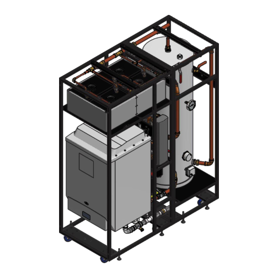
WATER HEATER TECHNICAL DATA WHP070 / WHP050 WHP090 / WHP115 Overall Frame Size 1200mm x 700mm x 1965mm high 1535mm x 700mm x 1965mm high Weight Empty 220kg 300kg Weight full 450kg 525kg Front Section (FS) Size 565mm x 700mm x 1965mm high... - Page 6 3.0 SCHEMATIC LAYOUTS PREMIUM PLUS WATER HEATER Blade 50,70,90,115 Premium Plus Water Heater Manual July 2020...
- Page 7 3.1 SCHEMATIC LEGEND Blade 50,70,90,115 Premium Plus Water Heater Manual July 2020...
-
Page 8: Installation Requirements
The Blades water heaters are delivered in two basic configurations: The WHP050 and WHP070 PREMIUM PLUS are delivered with the two sections assembled and secured to the transport pallet in the normal way and ready for installation. - Page 9 The PREMIUM PLUS Water Heater are delivered in two basic configurations: The WHP050 and WHP070 are delivered with the two sections assembled and secured to the transport pallet in the normal way and ready for installation.
- Page 10 5.1 WHP050 / WHP070 PREMIUM PLUS WATER HEATER Disconnecting Procedure Disconnect the following compression fitting and ensure compression nut are loose Item ‘A’ Pre-heat cold feed compression valve Item ‘B’ Incoming Main compression straight coupling Item ‘C’ Cylinder circulating Flow compression valve Item ‘D’...
-
Page 11: Equipment Details
6.0 EQUIPMENT DETAILS 6.1 CYLINDER All cylinders are purpose made to Blade specific designs by a leading manufacture, the construction is fully welded stainless steel and approved for mains pressure or gravity systems and come complete with ERP compliant high-density insulation and solid external powder coated finish. They come in two standard sizes 300 and 200 litres other sizes are available as special orders details on request. - Page 12 Failure to provide adequate treatment may invalidate the warranty. WATER HEATER MODELS PLATE HEAT EXCHANGER SCHEDULE WHP050 WHP070 WHP090 WHP115 Duty rating...
- Page 13 6.4 DHW TIME CLOCK PROGRAMMING Current time and day setting Press the R button to reset the timer to its default settings, activate using a pencil or similar pointed Instrument. (pressing R will delete all stored programmes). Press Y to enter function setup. (Note: if another button is not pressed within 10 seconds the display will revert to the normal screen).
- Page 14 Summer Time Setting 1) Press the Y button, then use the + or - buttons to scroll through to “summer” (flashing). 2) Press the Y button again to access the summer time setting. 3) Press the + or - button to change between summer on or off. 4) Press Y to confirm summer setting, time will advance 1 hour.
- Page 15 6.5 DHW CYLINDER THERMOSTAT User explanation A cylinder thermostat switches on and off the heat supply from the boiler to the hot-water cylinder. It works by sensing the temperature of the water inside the cylinder, switching on the water heating when the temperature falls below the thermostat setting, and switching it off once this set temperature has been reached.
- Page 16 2. Release the button and after approx. 10 seconds press and hold the HOLIDAY button again. After 5 seconds the red LED will light up and an audible click is heard, keep the HOLIDAY button pressed for a further 5 seconds until the LCD display flashes.
-
Page 17: Fixing Details
7.0 FIXING DETAILS Base Plans for WHP050, WHP070, WHP090 & WHPH115 Showing fixing details Frame Fixing Bracket Frame Levelling and Immobilisation Detail Blade 50,70,90,115 Premium Plus Water Heater Manual July 2020... -
Page 18: General Services Requirements
8.0 GENERAL SERVICES REQUIREMENTS 8.1.1 For site services connection information, refer to the connection diagrams. All connections should be made in accordance with current building regulations. 8.1.2 The electrical and controls connections should be made in an approved manner, and the unit should be earthed in accordance with building regulations. - Page 19 9.0 MAINTENANCE AND SERVICING CLEARANCES Blade 50,70,90,115 Premium Plus Water Heater Manual July 2020...
-
Page 20: Frame Details
10.0 FRAME DETAILS 90-115kW PREMIUM PLUS WATER HEATER Blade 50,70,90,115 Premium Plus Water Heater Manual July 2020... - Page 21 50-70kW PREMIUM PLUS WATER HEATER Blade 50,70,90,115 Premium Plus Water Heater Manual July 2020...
- Page 22 11.0 FLUE SYSTEM FOR THE PREMIUM PLUS WATER HEATER This Water Heater is ONLY suitable for an OPEN flue or a TWIN pipe system OPEN FLUE (TYPE B23 FLUE) The Blade Servers leave the factory with B23 type flue configuration (open chamber and forced draught single flue pipe) and receives the air for combustion from the openings in the rear of the boiler therefore air supply for combustion and ventilation must be provided in accordance with BS 6644 &...
- Page 23 FLUE JOINTING All joints must be made using the following technique Step 1 Cut pipe square and de-burr Step 2 Lubricate surfaces with provided silicone grease prior to push fitting. BLADE FLUE MANIFOLDS FLUE MANIFOLD FOR 50 AND 70kW BOILERS FLUE MANIFOLD FOR 90 AND 115kW BOILERS The 90kW boiler only has three PFGHRD units...
- Page 24 FLUE INSTALLATION DETAILS 50kW and 70kW BOILERS Blade 50,70,90,115 Premium Plus Water Heater Manual July 2020...
- Page 25 FLUE INSTALLATION DETAILS 90kW and 115kW BOILERS Blade 50,70,90,115 Premium Plus Water Heater Manual July 2020...
-
Page 26: Installation Schematic
12.0 INSTALLATION SCHEMATIC LAYOUT Blade 50,70,90,115 Premium Plus Water Heater Manual July 2020... -
Page 27: Conversion To Space Heating Details
13.0 CONVERSION TO SPACE HEATING DETAILS The Water Heater can be supplied factory converted and configured to supply both DHW and space heating on request Blade 50,70,90,115 Premium Plus Water Heater Manual July 2020... -
Page 28: Routine Servicing
14.0 ROUTINE SERVICING Follow the Boiler Manufactures recommendations for Boiler Servicing but it should also include the following items as required but at a minimum of 1-year intervals to maintain the Water Heater warranties. 1) DHW cylinder check operation of the P&TRV 2) Expansion Vessel cold and hot operating pressures to be checked 3) Check incoming water Main pressure To maintain the boiler and Water Heater guarantee all the above actions must be carried out including... -
Page 29: Wiring Diagram
15.0 WIRING DIAGRAM Blade 50,70,90,115 Premium Plus Water Heater Manual July 2020... -
Page 30: Short Parts List
16.0 SHORT PARTS LIST WATER HEATER Description PART No WHP070 WH0090 WHP115 WHP050 B1-70-WHP1-1 B1-90-WHP1-1 B1-115-WHP1-1 DHW Plate Heat Exchanger B1-50-WHP1-1 B1-70-WHP1-2 B1-90-WHP1-2 B1-115-WHP1-2 DHW Pump B1-50-WHP1-2 B1-70-WHP1-3 B1-90-WHP1-3 B1-115-WHP1-3 200L DHW Storage Cylinder B1-50-WHP1-3 B1-70-WHP1-4 B1-90-WHP1-4 B1-115-WHP1-4 300L DHW Storage Cylinder... -
Page 31: Commissioning Details
17.0 COMMISSIONING DETAILS Customer Details Installation Address Telephone Number Installer Details Address Telephone Number e-mail address System Summary Boiler Serial No. PFGHRD Serial No. Pump Serial No. Cylinder Serial No. Plate Heat Serial No. Boiler Commission Gas Testing Cert Declaration (to be completed by the installer): I confirm that the above system has been installed and commissioned at the above address. - Page 32 Commissioning and Annual Servicing Checklist Site Comments/ Design Check Measurement Units Parameter Heating System Pressurised 1.0 bar Domestic System Pressure Adjusted when Cold 3.0 bar Flue Visual Inspection (during smoke test) Tick Boiler Commissioned Tick Gas tightness Test completed Tick Flue gas Analysed Tick DFHW Open Vent Fitted...
-
Page 33: Service Records
SERVICE Telephone RECORD 01566 770799 It is recommended that your heating system is serviced regularly (minimum annually) and that the appropriate service interval Record is completed SERVICE PROVIDER Before completing the appropriate Service Record below please ensure you have carried out the service as described in the manufacturer’s instructions Always use the manufacturer’s specified spare parts when replacing controls Service 01... - Page 34 SERVICE Telephone RECORD 01566 770799 It is recommended that your heating system is serviced regularly (minimum annually) and that the appropriate service interval Record is completed SERVICE PROVIDER Before completing the appropriate Service Record below please ensure you have carried out the service as described in the manufacturer’s instructions Always use the manufacturer’s specified spare parts when replacing controls Service 05...
- Page 35 SERVICE Telephone RECORD 01566 770799 It is recommended that your heating system is serviced regularly (minimum annually) and that the appropriate service interval Record is completed SERVICE PROVIDER Before completing the appropriate Service Record below please ensure you have carried out the service as described in the manufacturer’s instructions Always use the manufacturer’s specified spare parts when replacing controls Service 09...
- Page 36 SERVICE Telephone RECORD 01566 770799 It is recommended that your heating system is serviced regularly (minimum annually) and that the appropriate service interval Record is completed SERVICE PROVIDER Before completing the appropriate Service Record below please ensure you have carried out the service as described in the manufacturer’s instructions Always use the manufacturer’s specified spare parts when replacing controls Service 13...
-
Page 37: Notes
Notes Blade 50,70,90,115 Premium Plus Water Heater Manual July 2020... -
Page 38: Appendix "A" Alpha Boiler Manual
APPENDIX A ALPHA BOILER MANUAL... -
Page 39: Installation
Installation and Servicing Instructions Alpha Pro Tec Plus 50, 70, 90 and 115 Wall Mounted, Fan Assisted, Gas Fired, High Efficiency Condensing System Boilers For Technical help or for Service call ... ALPHA HELPLINE Tel: 0344 871 8764 website: www.alpha-innovation.co.uk... - Page 40 Service Interval Record and left with the householder. www.centralheating.co.uk Useful contact details: Gas Safe Register - 0800 408 5577 - www.gassaferegister.co.uk Alpha Heating Innovation: General Sales Enquiries - 0344 871 8760 Technical Helpline - 0344 871 8764 Alpha ProTec Plus 50, 70, 90, 115 - Benchmark Scheme...
- Page 41 Service record ........52 INTRODUCTION The Alpha Pro Tec Plus range are wall mounted high efficiency condensing, fan assisted system boilers. The burner is lit electronically and the heat output is controlled by a modulating fan and gas valve. These are system boilers providing heating only for sealed central heating systems. However, they may be used with an open central heating system if required - refer to Section 3.8.
-
Page 42: Safety Symbols
The user must not dispose of the appliance at the end of its service life as municipal waste, but send it to appropriate collection centres. PERSONAL PROTECTIVE EQUIPMENT SAFETY GLOVES SAFETY GOGGLES SAFETY FOOTWEAR Alpha Pro Tec Plus 50, 70, 90, 115 - Safety Symbols... -
Page 43: General Data
1038 1038 Width Depth Clearances for servicing Bottom Top (horizontal flue) Top (vertical flue) Sides Front Boiler dry lift weight Boiler operating weight (full of water) approx. Water content litre Alpha Pro Tec Plus 50, 70, 90, 115 - Data... - Page 44 Hole in wall required mm Flue system (as supplied) Open flue Hole in wall required mm * Maximum Flue Lengths (includes first bend onto boiler flue connection for horizontal installations) Alpha Pro Tec Plus 50, 70, 90, 115 - Data...
- Page 45 2. It is recommended that horizontal and vertical flue assemblies should be supported approximately every 1.5 m with access provided to the joints. 3. These dimensions only apply for flue parts supplied by Alpha. Cascade flue options are also available, please contact Alpha for further details. PUMP The boiler is equipped with a low power consumption pump.
- Page 46 Pro Tec Plus 90 pump (25 - 125) 1000 1500 2000 2500 3000 3500 4000 4500 5000 5500 6000 6500 Flow rate (l/h) A = Available pump head B = Pump power consumption (dotted area) Fig. 3.3 Alpha Pro Tec Plus 50, 70, 90, 115 - Data...
- Page 47 3.024245 connected to the common flow circuit and linking the bus connections in the boiler as shown in Fig. 3.6. With this configuration the master boiler can be controlled normally with external controls connected and the two boilers will function in sequence as a cascade. Contact Alpha for further details on this function. Fig. 3.6...
-
Page 48: Safety
Primary flow switch Combustion chamber cover Burner Heat exchanger Air inlet pipe Air pressure switch Venturi Flue sensor Automatic air vent Heat exchanger automatic air vent Pump Thermofuse Gas valve Fig. 3.7 Alpha Pro Tec Plus 50, 70, 90, 115 - Data... - Page 49 Air inlet pipe Thermofuse Ignition electrode Flame sensing electrode Combustion chamber cover Manifold cover Heat exchanger Venturi Flue hood Pump Flue sampling point Condensate trap Air sampling point Fig. 3.8 Alpha Pro Tec Plus 50, 70, 90, 115 - Data...
- Page 50 Alpha Pro Tec Plus boilers leave the factory with 'B23' type flue configuration (open chamber and forced draught - single flue pipe). To change the configuration to 'C' type (sealed chamber and forced draught - concentric flue pipe), remove the 80 mm dia.
- Page 51 45° bend is equivalent to 1.4 m of flue length Pro Tec Plus model 80/125 mm Concentric flue 14.5 m 11 m 80 mm Open flue 30 m 28 m 14 m 8.5 m Fig. 4.1 Alpha Pro Tec Plus 50, 70, 90, 115 - General Boiler Information...
- Page 52 Fig. 4.2 FLUE TERMINATION The Alpha Pro Tec Plus range of boilers can be individually flued using either 80 mm open flue configuration or 80/125 mm concentric flue. Multiple boilers can be individually flued or cascade flue kits are also available in 150 mm or 200 mm.
- Page 53 Filling of the system must be carried out in a manner approved by the local Water Undertaking. Drain taps (to BS 2879) must be used to allow the system to be completely drained. Alpha Pro Tec Plus 50, 70, 90, 115 - General Boiler Information...
- Page 54 4.10 FLUSHING THE HEATING SYSTEM It is essential that the central heating system is thoroughly cleaned and flushed before fitting an Alpha Pro Tec Plus boiler. Failure to do so will invalidate the warranty. If this is difficult because the system is old/dirty refer to Section 4.8, Fig.
-
Page 55: Installation
80 Dia. E - Electrical connection G - Gas supply HR - Heating return HF - Heating flow CD - Condensate drain SV - Safety valve outlet (tundish) Fig. 5.1 Alpha Pro Tec Plus 50, 70, 90, 115 - Installation... - Page 56 HEATING HEATING SAFETY RETURN FLOW VALVE (28 mm) (11/2" BSP) (3/4" BSP) (11/2" BSP) MINIMUM BOTTOM CLEARANCE 250 mm necessary. Fig. 5.3 Alpha Pro Tec Plus 50, 70, 90, 115 - Installation...
- Page 57 30 mm per metre). When installing the extensions, a wall/ceiling mounted clamp must be installed at least every 1.5 metres. All joints between flue sections should be connected using the clamps provided. It is not required to add additional screws through the clamps and into the flue sections. Alpha Pro Tec Plus 50, 70, 90, 115 - Installation...
- Page 58 80/125 mm diameter Square gasket Pro Tec Plus 50 14.5 m Concentric flue pipe Adapter Pro Tec Plus 70 11 m Pro Tec Plus 90 Pro Tec Plus 115 Fig. 5.9 Alpha Pro Tec Plus 50, 70, 90, 115 - Installation...
- Page 59 Leave the control panel open until commissioning procedures have been completed. Carry out electrical system checks - Short circuit, Polarity, Earth continuity and Resistance to earth with a suitable multimeter. Alpha Pro Tec Plus 50, 70, 90, 115 - Installation...
- Page 60 Fig. 5.11 Alpha Pro Tec Plus 50, 70, 90, 115 - Installation...
- Page 61 EXTERNAL TEMPERATURE PROBE - Fig. 5.12 Alpha Pro Tec Plus boilers can be controlled using the Alpha Single Boiler Controller (available as an optional kit), or with the installation of an alternative programmer/room thermostat. These must be 'volt free' switching. In either scenario the external probe can be connected directly to the boiler electrical connections G and J, refer to the external probe instruction sheet for positioning on an external wall.
- Page 62 2 (P3) 1 - Inlet gas pressure point 2 - Outlet gas pressure point 2 (P3) 3 - Off/Set adjustment screw (minimum) 4 - Outlet flow regulator (maximum) Fig. 6.1 Alpha Pro Tec Plus 50, 70, 90, 115 - Commissioning...
- Page 63 Then the fan runs at ignition speed and the ignition cycle commences. If during the cycle the pressure switch doesn't close the contacts (i.e. the flue system is blocked or restricted), after 50 seconds fault A4 is displayed. Alpha Pro Tec Plus 50, 70, 90, 115 - Commissioning...
- Page 64 Fig. 6.7 In the standby mode the boiler is still switched on but not active, maintaining the anti-freeze function. To turn it back on simply press button 'B'. RESET Fig. 6.8 Alpha Pro Tec Plus 50, 70, 90, 115 - Commissioning...
- Page 65 °C / °F Flow temperature requested by system in DHW °C / °F Not used Number of burner cycles in simple cascade (cascade only) Number of display counted (cascade only) Alpha Pro Tec Plus 50, 70, 90, 115 - Commissioning...
- Page 66 Note: It is a requirement that the installation is registered by the installer through the Gas Safe Gas Work Notification Scheme. 12. Leave these Installation and Servicing instructions with the User for use on future calls. Alpha Pro Tec Plus 50, 70, 90, 115 - Commissioning...
- Page 67 11. Record all the required readings in the Service Record at the back of this manual. To maintain the boiler guarantee all the above actions must be carried out and recorded in the Service Record at the back of this manual. Alpha Pro Tec Plus 50, 70, 90, 115 - Routine Servicing...
- Page 68 (view 'A' in Fig. 6.1) Lower the panel out and away from the top cover. Note: If only the front panel is to be removed, remove as described in Section 5.7, paragraph 1. View A Fig. 7.1 (Pro Tec Plus 70 shown) Alpha Pro Tec Plus 50, 70, 90, 115 - Routine Servicing...
- Page 69 Check the operation of the boiler. Return all controls to their original settings. Place the case or front case panel in position and secure in position with the screws previously removed, see Section 7.2. Alpha Pro Tec Plus 50, 70, 90, 115 - Routine Servicing...
- Page 70 Flow manifold Air pressure switch Safety valve 4 bar Flue sensor Gas cock Automatic air vent Tundish Test points (air A) - (flue F) Fig. 7.4 Pro Tec Plus 50 Alpha Pro Tec Plus 50, 70, 90, 115 - Routine Servicing...
- Page 71 Flow manifold Flue hood manifold Safety valve 4 bar Air intake pipe Test points (air A) - (flue F) Spark generator Fig. 7.5 Pro Tec Plus 70, 90, 115 Alpha Pro Tec Plus 50, 70, 90, 115 - Routine Servicing...
- Page 72 S20 Room thermostat (optional) X40 Factory fitted link X90 Configuration link (with or without air pressure switch) WARNING: Gas valve ISOLATE ELECTRICAL SUPPLY BEFORE REMOVING ANY COVERS Suppression filter Fig. 8.1 Alpha Pro Tec Plus 50, 70, 90, 115 - Wiring Diagram...
- Page 73 Check return sensor resistance values. 0A80 Flow and return sensor connection fault. Check the wires are connected to the correct sensors. Fault may occur after several minutes of boiler operation. Alpha Pro Tec Plus 50, 70, 90, 115 - Fault Finding...
- Page 74 This may occur if the main PCB or display PCB is changed. Check for correct parameter settings on PCB. Press '-' CH button until 'AUTO' appears, then press and hold 'RESET' button until 'bu1' appears. Alpha Pro Tec Plus 50, 70, 90, 115 - Fault Finding...
-
Page 75: Figure 10: Display
The boiler is supplied with the PCB configuration set according to the boiler model, however it is possible to adjust certain parameters according to the boiler and system configuration. Note: These parameters should only be adjusted by an approved Alpha engineer or Agent. To access the programming menu, press and hold buttons 'B' and 'C' simultaneously. - Page 76 0 - 10 V control feature (0 = temperature, 1 = heat output) External sensor fault 0 - 1 For cascade function (0 = none, 1 = fitted) Alpha Pro Tec Plus 50, 70, 90, 115 - Programming the Boiler PCB...
- Page 77 (m³/h) (rpm) (kg/h) (rpm) 90.0 9.77 6700 7.17 6350 78.0 8.45 5780 6.20 5530 67.0 7.25 4980 5.32 4800 56.0 6.06 4210 4.45 4090 45.0 3480 3.58 3400 4.88 Alpha Pro Tec Plus 50, 70, 90, 115 - Performance Data...
- Page 78 9.76 5680 7.16 5620 83.0 9.00 5260 6.60 5190 8.24 4850 6.05 4760 76.0 69.0 7.48 4440 5.49 4350 62.0 6.72 4040 4.93 3940 55.0 5.97 3650 4.38 3550 Alpha Pro Tec Plus 50, 70, 90, 115 - Performance Data...
- Page 79 12 CASCADE SYSTEM INSTALLATION Alpha Pro Tec Plus 50, 70, 90, 115 - Cascade System Installation...
- Page 80 Complete boiler seal kit 3.025045 Ignition electrode lead 1.035386 Air pressure switch - Pro Tec Plus 50, 90, 115 1.041722 Air pressure switch - Pro Tec Plus 70 1.041723 Alpha Pro Tec Plus 50, 70, 90, 115 - Short Parts List...
-
Page 81: Energy Classification
(*) High temperature regime means 60°C return temperature at heater inlet and 80°C feed temperature at heater outlet. (**) Low temperature means for condensing boilers 30°C, for low-temperature boilers 37°C and for other heaters 50°C return temperature. Alpha Pro Tec Plus 50, 70, 90, 115 - Energy Classification... - Page 82 (*) High temperature regime means 60°C return temperature at heater inlet and 80°C feed temperature at heater outlet. (**) Low temperature means for condensing boilers 30°C, for low-temperature boilers 37°C and for other heaters 50°C return temperature. Alpha Pro Tec Plus 50, 70, 90, 115 - Energy Classification...
- Page 83 (AFC) Seasonal room heating yield (ηs) 92 % Seasonal room heating yield (ηs) 92 % Domestic hot water production yield (ηwh) ------- Domestic hot water production yield (ηwh) ------ Alpha Pro Tec Plus 50, 70, 90, 115 - Energy Classification...
- Page 84 Alpha Pro Tec Plus 50, 70, 90, 115 - Energy Classification...
- Page 85 * To be established by means of table 5 of Regulation 811/2013 in case of “assembly” including a heat pump to integrate the boiler. In this case the boiler must be considered as the main appliance of the assembly. Alpha Pro Tec Plus 50, 70, 90, 115 - Energy Classification...
- Page 86 Pro Tec Plus 70 ‘I’ ‘II’ ‘III’ ‘IV’ * To be determined according to Regulation 811/2013 and transient calculation methods as per Notice of the European Community no. 207/2014. Alpha Pro Tec Plus 50, 70, 90, 115 - Energy Classification...
- Page 87 Page left intentionally blank...
- Page 88 GAS BOILER SYSTEM COMMISSIONING CHECKLIST This Commissioning Checklist is to be completed in full by the competent person who commissioned the boiler as a means of demonstrating compliance with the appropriate Building Regulations and then handed to the customer to keep for future reference. Failure to install and commission according to the manufacturer’s instructions and complete this Benchmark Commissioning Checklist will invalidate the warranty.
-
Page 89: Service Record
SERVICE RECORD It is recommended that your heating system is serviced regularly and that the appropriate Service Interval Record is completed. Service Provider Before completing the appropriate Service Record below, please ensure you have carried out the service as described in the manufacturer’s instructions. Always use the manufacturer’s specifed spare part when replacing controls. - Page 90 These instructions have been carefully prepared but we reserve the right to Sevenoaks, Kent TN15 7RS alter the specification at any time in the interest of product improvement. Tel: 0344 871 8764 © Alpha Therm Limited 2019. email: info@alpha-innovation.co.uk website: www.alpha-innovation.co.uk 1.043480 rev. ST.004218/000 Part No.
- Page 91 APPENDIX B DAB PUMP MANUAL Blade 50,70,90,115 Premium Plus Water Heater Manual July 2020...
- Page 92 ENGLISH INDEX KEY ................................30 GENERAL ..............................30 Safety ..............................30 Responsibility ..........................30 Particular warnings ......................... 30 PRODUCT DESCRIPTION ........................31 PUMPED LIQUIDS ........................... 31 APPLICATIONS ............................32 TECHNICAL DATA ..........................32 MANAGEMENT ............................33 Storage ............................. 33 Transport ............................33 Weight ..............................
- Page 93 ENGLISH INDEX OF TABLES Table 1: Functions ............................31 Table 2: Technical data ........................... 32 Table 3: Maximum head (Hmax) and maximum flow rate (Qmax) of EVOSTA2, EVOSTA3 circulators ..33 Table 4: Mounting the Evosta3 connector ....................... 39 Table 5: Mounting the Evosta2 connector ....................... 40 Table 6: Pump operating modes........................
-
Page 94: Particular Warnings
ENGLISH 1. KEY The frontispiece shows the version of this document in the form Vn.x. This version indicates that the document is valid for all software versions of the device n.y. For example: V3.0 is valid for all Sw: 3.y. In this document the following symbols will be used to avoid situations of ranger: Situation of general danger. -
Page 95: Product Description
ENGLISH Mains terminals and motor terminals may still have dangerous voltage when the motor is stopped. If the power cable is damaged, it must be replaced by the technical assistance service or by qualified personnel, so as to avoid any risk. 3. -
Page 96: Technical Data
ENGLISH 5. APPLICATIONS EVOSTA2, EVOSTA3 series circulators allow integrated adjustment of the differential pressure which enables the circulator performance to be adapted to the actual requirements of the system. This determines considerable energy saving, a greater possibility of control of the system, and reduced noise. EVOSTA2, EVOSTA3 circulators are designed for the circulation of: –... -
Page 97: Table 3: Maximum Head (Hmax) And Maximum Flow Rate (Qmax) Of Evosta2, Evosta3 Circulators
ENGLISH EVOSTA2, EVOSTA3 Hmax [m] Qmax [m EVOSTA2 40-70/xxx M230/50-60 EVOSTA2 80/xxx M230/50-60 EVOSTA3 40/xxxM230/50-60 EVOSTA3 60/xxx M230/50-60 EVOSTA3 80/xxx M230/50-60 Table 3: Maximum head (Hmax) and maximum flow rate (Qmax) of EVOSTA2, EVOSTA3 circulators 7. MANAGEMENT Storage All the circulators must be stored in a dry covered place, with possibly constant air humidity, free from vibrations and dust. -
Page 98: Mechanical Installation
ENGLISH Mechanical installation Figure 2: Mounting EVOSTA2 or EVOSTA3 The arrows on the pump housing indicate the flow direction through the pump. See fig. 1, pos. A. 1. Fit the two gaskets when you mount the pump in the pipe. See fig. 1, pos. B. 2. -
Page 99: Figure 4: Positions Of The User Interface
ENGLISH − To facilitate control and maintenance operations, install an interception valve both on the suction pipe and on the delivery pipe. − Before installing the circulator, accurately flush the system with only water at 80°C. Then drain the system completely to eliminate any harmful substance that may have got into circulation. -
Page 100: Rotation Of The User Interface
ENGLISH 8.2.2 Positioning of the user interface in conditioning and cold water systems The user interface can be positioned only with the cable facing downwards. Figure 5: Positions of the user interface Rotation of the user interface If the circulator is installed on pipes in a horizontal position, it will be necessary to rotate the interface with the respective electronic device through 90 degrees in order to maintain the grade of IP protection and to allow the user a more convenient interaction with the graphic interface. -
Page 101: Non-Return Valve
ENGLISH ATTENTION Water at high temperature. High temperature. ATTENTION System under pressure - Before dismantling the pump, empty the system or close the interception valves on both sides of the pump. The pumped liquid may be at a very high temperature and high pressure. -
Page 102: Electrical Connections
ENGLISH 9. ELECTRICAL CONNECTIONS The electrical connections must be made by expert, qualified personnel. ATTENTION! ALWAYS RESPECT THE LOCAL SAFETY REGULATIONS. Always switch off the mains power supply before working on the electrical or mechanical part of the system. Wait for the warning lights on the control panel to go out before opening the appliance. -
Page 103: Table 4: Mounting The Evosta3 Connector
ENGLISH EVOSTA3 Phase Fit nut and connector on the Unscrew the cable gland nut cable. Strip the wires as and extract the terminal board Rotate the terminal board indicated in the figure. Action from the connector, releasing it through 180°. Connect the wires to the from the side clips. -
Page 104: Table 5: Mounting The Evosta2 Connector
ENGLISH EVOSTA2 Phase Fit nut and connector on the cable. Strip the wires as Unscrew the cable gland indicated in the figure. Connect Action nut and extract the terminal Remove the retaining screw. the wires to the terminal board, board from the connector. respecting the phase, neutral and earth. - Page 105 ENGLISH It is dangerous to touch the circulator. DANGER OF SCALDING!
-
Page 106: Degassing The Pump
ENGLISH Once all the electrical and hydraulic connections have been made, fill the system with water and if necessary with glycol (for the maximum glycol percentage see par. 3) and feed the system. Once the system has been started it is possible to modify the operating modes to adapt better to the plant requirements (see par.12). -
Page 107: Regulating Modes
ENGLISH FUNCTIONS 11.1 Regulating Modes EVOSTA2, EVOSTA3 circulators allow the following regulating modes depending on plant requirements: − Proportional differential pressure regulation depending on the flow present in the plant. − Constant differential pressure regulation. − Regulation with constant curve. The regulating mode may be set through the EVOSTA2, EVOSTA3 control panel. -
Page 108: Regulation With Constant Differential Pressure
ENGLISH 11.1.2 Regulation with Constant Differential Pressure In this regulating mode the differential pressure is kept constant, irrespective of the demand for water, The Hs set point may be set from the display. Regulation indicated for: – Heating and conditioning plants with low load losses –... -
Page 109: Control Panel
ENGLISH CONTROL PANEL The functions of EVOSTA2, EVOSTA3 circulators can be modified by means of the control panel on the cover of the electronic control device. 12.1 Elements on the Display Figure 10: Display Luminous segments indicating the type of set curve Display showing the instantaneous power absorption in Watt, the flow rate in m /h, the head in metres and the set curve. - Page 110 ENGLISH 12.2.3 Display Operation Figura 11: Evosta3 Display The Evosta3 circulator has a display that is able to show the following values. Height of the selected curve (1-2-3) Instantaneous power absorption in Watt Instantaneous head in m Instantaneous flow rate in m3/h The values are shown in sequence for 3".
-
Page 111: Table 6: Pump Operating Modes
ENGLISH 12.2.4 Settings of the pump operating mode EVOSTA3 EVOSTA2 Lower curve with proportional pressure, PP1 Intermediate curve with proportional pressure, PP2 Higher curve with proportional pressure, PP3 Lower curve with constant pressure, CP1 Intermediate curve with constant pressure, CP2 Higher curve with constant pressure, CP3 Lower constant curve, I Intermediate constant curve, II... -
Page 112: Factory Settings
ENGLISH FACTORY SETTINGS Regulating mode: = Minimum proportional differential pressure regulation TYPES OF ALARM Alarm Description No. of curve height blinks EVOSTA2 TRIP: loss of motor control, may be caused by incorrect parameters, 2 Blinks blocked rotor, disconnected phase, disconnected motor 3 Blinks SHORT CIRCUIT: short circuit on phases or between phase and earth 4 Blinks... - Page 113 ENGLISH DIMENSIONS Evosta 2 Dimensions Mod. 1” EVOSTA2 40-70/80/130 (1/2") M230/50-60 Ø91 1”1/2 EVOSTA2 40-70/80/130 (1") M230/50-60 Ø91 1”1/2 EVOSTA2 40-70/80/180 (1") M230/50-60 Ø91 2” EVOSTA2 40-70/80/180 (1"1/4) M230/50-60 Ø91...
- Page 114 ENGLISH Evosta 3 Dimensions Mod. 1” EVOSTA3 40/60/80/130 (1/2") M230/50-60 78,5 Ø91 107,5 1”1/2 EVOSTA3 40/60/80/130 (1") M230/50-60 78,5 Ø91 107,5 1”1/2 EVOSTA3 40/60/80/180 (1") M230/50-60 78,5 Ø91 107,5 2” EVOSTA3 40/60/80/180 (1"1/4) M230/50-60 78,5 Ø91 107,5...
-
Page 115: Performance Curves
ENGLISH PERFORMANCE CURVES EVOSTA2 40-70/XXX... - Page 116 ENGLISH EVOSTA2 80/XXX...
- Page 117 ENGLISH EVOSTA3 40/XXX...
- Page 118 ENGLISH EVOSTA3 60/XXX...
- Page 119 ENGLISH EVOSTA3 80/XXX...
- Page 120 BLADES LOW CARBON SYSTEMS Ltd 4 Valhalla Industrial Estate, Holsworthy, Devon EX22 6HN For Technical help or Service call...01566 770799 info@bladeslcs.co.uk www.bladeslcs.co.uk...
Need help?
Do you have a question about the WHP050 and is the answer not in the manual?
Questions and answers