Table of Contents
Advertisement
Available languages
Available languages
Quick Links
INSTALLER:
Leave this manual with the appliance.
CONSUMER:
Retain this manual for future reference.
SAFETY INFORMATION
WARNING
!
If the information in these instructions are not followed exactly, a fi re
or explosion may result causing property damage, personal injury or
death. Please read the entire manual before you install and use your
appliance. This heeater has not been tested with an unvented gas log
set. To reduce risk of fi re or injury, do not install an unvented gas log
set into the heater.
- This heater can be very hot when burning.
- Combustible materials such as fi rewood, wet clothing, etc. placed
too close can catch fi re.
- Children and pets must be kept from touching the heater when it is
hot.
- The chimney must be sound and free of cracks. Before installing
this appliance, contact the local building or fi re authority and follow
their guidelines.
- Operate only with the doors tightly closed.
- Burn wood behind the log retainer directly on the fi rebricks.
- Do not use an elevated grate or otherwise raise the fi re.
- This appliance is designed to burn natural wood only. Higher
effi ciencies and lower emissions generally result when burning air
dried seasoned hardwoods, as compared to softwoods or to green
or freshly cut hardwoods.
- Do not start a fi re with chemicals or fl uids such as gasoline, engine
oil, etc.
- Do not burn trash or garbage, lawn clippings/waste, rubber,
waste petroleum products, paints or paint thinners/solvents, plastic,
materials containing asbestos, construction debris, railroad ties or
treated wood, manure or animal remains, salt water driftwood or
salted materials, unseasoned wood, coal, charcoal, coloured paper,
cardboard, plywood or particleboard. Burning these materials may
result in release of toxic fumes or render the appliance ineffective and
cause smoke.
- Do not let the appliance become hot enough for any part to glow
red.
Wood Stoves ONLY
- At least 14 squares inches (90.3 square centimeters) of outside air
must be admitted to the room or directly to the appliance through a
4" (101.6mm) diameter pipe.
- KEEP THE STOVE TOP TEMPERATURE BELOW 700°F (371°C).
Attempts to achieve heat output rates that exceed design
specifications can result in steel distortion and damage.
Wolf Steel Ltd., 24 Napoleon Rd., Barrie, ON, L4M 0G8 Canada / 103 Miller Drive, Crittenden, Kentucky, USA, 41030
Phone 1 (866) 820-8686 • www.timberwolffi replaces.com • ask@timberwolffi replaces.com
$10.00
ADD SAFETY STANDARD INFORMATION
& EPA QUALIFICATION (IF APPLICABLE)
ENGLISH
FRENCH PG. 59
W415-2827 / A / 08.20.21
Advertisement
Chapters
Table of Contents
Troubleshooting

Subscribe to Our Youtube Channel
Related Manuals for Timberwolf TZ3000H


Summary of Contents for Timberwolf TZ3000H
- Page 1 Wolf Steel Ltd., 24 Napoleon Rd., Barrie, ON, L4M 0G8 Canada / 103 Miller Drive, Crittenden, Kentucky, USA, 41030 Phone 1 (866) 820-8686 • www.timberwolffi replaces.com • ask@timberwolffi replaces.com W415-2827 / A / 08.20.21...
- Page 2 safety information • This appliance is hot when operated and can cause severe burns if contacted. • Any changes or alterations to this appliance or its controls can be dangerous and is prohibited. • Do not operate appliance before reading and understanding operating instructions.
- Page 3 safety information • Y o ur app liance req uires perio d ic m ain tenance and clean in g . Failure to m aintain yo ur app liance m ay lead to sm o ke spillag e in yo ur hom e. •...
-
Page 4: Table Of Contents
table of contents dimensions operation appliance operation general information bypass door specifi cations catalyst general instructions operating sounds, smells and rating plate information characteristics high effi ciency heating air control 2.4.1 hot air gravity vent system (NZ220) 8 fi re extinguishers / smoke and carbon 2.4.2 central heating system (NZ62CH) monoxide detectors fuel loading and burn cycle... -
Page 5: Dimensions
dimensions 1.0 dimensions W415-2827 / A / 08.20.21... -
Page 6: General Information
2.0 general information general information WARNING • This appliance and its components are designed to be installed and operated as a system. Any alteration to or substitution for items in this system, unless allowed by these installation instructions, will void the CSA Group listing and may void the product warranty. -
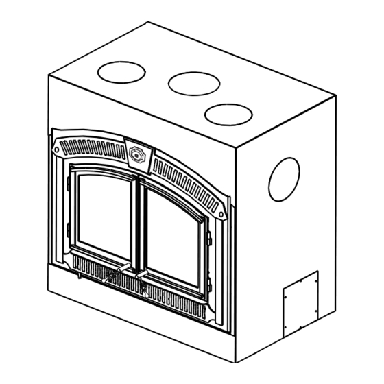
Page 7: Rating Plate Information
general information rating plate information Rating plate is located behind the appliance faceplate, underneath the fi rebox. This illustration is for reference only. Refer to the rating plate on the appliance for accurate information. note: The rating plate must remain with the appliance at all times. It must not be removed. W415-2827 / A / 08.20.21... -
Page 8: High Effi Ciency Heating
The TZ3000H is a high effi ciency appliance that may be operated as a standalone system, however, a blower is recommended to further enhance the effi ciency of the appliance. The TZ3000H and its optional heat distribution systems cannot be connected to other duct systems. The TZ3000H must be ducted independently when these installation options are used. -
Page 9: Central Heating System (Nz62Ch)
The NZ64 provides an ideal means of circulating warm air within the room it resides. The blower will only operate when the doors are fully closed. TZ3000H We recommend installing the blower in a different room or even a different level of the house. This will generate greater air movement and improve the distribution of the warm air cooling from the appliance as well as improving air movement in the summer months if using the summer bypass switch option. -
Page 10: Installation Planning
3.0 installation planning installation planning • Wear gloves, protective footwear and safety glasses for protection. • Carefully follow the instructions for assembly of the pipe and other parts needed to install the appliance. Failure to do so may result in a fi re, especially if combustibles are too close to the appliance or chimney and air spacers are blocked, preventing the free movement of cooling air. -
Page 11: Outside Combustion Air
Model TZ3000H has the option of taking outside air directly into the appliance through the opening on the left hand side or taking inside air through the lower front grille or a combination of both. For inside air, push in the control slider. -
Page 12: Fl Oor Protection
installation planning fl oor protection ember strip and hearth extensions 3.3.1 WARNING • Hearth extensions are to be installed only as described to prevent high temperatures from occurring on concealed combustible materials. Hearth ember strips prevent burning or hot particles from inadvertently falling directly on combustible surfaces in the event the building should settle and disturb the original construction. -
Page 13: Hearth Examples
installation planning hearth examples FLUSH HEARTH RAISED HEARTH RAISED APPLIANCE RAISED HEARTH AND APPLIANCE W415-2827 / A / 08.20.21... -
Page 14: Installation
installation 4.0 installation WARNING • Never install a single wall slip section or smoke pipe in a chase structure. The higher temperature of this single wall pipe may radiate suffi cient heat to combustible chase materials to cause a fi re. •... -
Page 15: Typical Chimney Installation
installation typical chimney installation W415-2827 / A / 08.20.21... -
Page 16: Adding Chimney Sections
installation adding chimney sections W415-2827 / A / 08.20.21... -
Page 17: Offset Chimney Installation
installation offset chimney installation W415-2827 / A / 08.20.21... -
Page 18: Installing Fl Ashing And Storm Collar
installation installing fl ashing and storm collar typical existing masonry The appliance may be connected to either a lined or unlined masonry chimney. IF THE CHIMNEY IS LINED: The fl ues must be made of vitrifi ed clay and be in sizes of 8”... -
Page 19: Framing
5.0 framing framing WARNING • In order to avoid the possibility of exposed insulation or vapour barrier coming in contact with the appliance body, it is recommended that the walls of the appliance enclosure be “fi nished” (ie. drywall/sheetrock), as you would fi... -
Page 20: Minimum Enclosure Clearances
framing minimum enclosure clearances A minimum of 6” (62mm) is required to combustibles from the side of the appliance. note: When constructing the enclosure, allow for fi nishing material thickness to maintain clearances. minimum mantel clearances • Risk of fi re. Maintain all specifi ed air space clearances to combustibles. Failure to comply with these instructions may cause a fi... - Page 21 fi nishing 6.0 fi nishing • Ventilation openings are required in enclosures up to 96” (244cm) high. They are recommended for all enclosures above 84” (213.4cm), combustible fi nishing materials may be used on the front face. • Use only a non-combustible material to fi nish the face of the appliance. A non-combustible material such as cement board is required for this purpose.
-
Page 22: Finishing
fi nishing ventilation openings note: As an alternate to grates, a 1” x 40” (25mm x 1016mm) wide gap can be left in the bottom and top of any fi nishing material to circulate the air from the fl oor, around the apppliance and out the top. W415-2827 / A / 08.20.21... -
Page 23: Baffl E Installation
During shipping, the catalyst may have shifted from its proper location. Prior to initial burn, ensure the catalyst is correctly installed. Refer to the “catalyst inspection and replacement” section. The TZ3000H contains a ceramic fi bre baffl e, catalyst and catalyst shield. It is important that each of these components are installed correctly prior to operating the appliance. -
Page 24: Faceplate Installation
fi nishing faceplate installation template removal 6.3.1 Remove the screws and template, discard only the template once all the facing material has been installed. Retain the screws for installing the faceplate. faceplate, hinge, ash lip and air control arm installation 6.3.2 WARNING •... -
Page 25: Door Installation
fi nishing door installation 6.3.3 Left Door Right Door 1. Install the left door handle through the left door 2. Install the right door handle through the right door assembly. Secure using the lock washer and nut assembly. provided. Install the three fl at washers and the door latch as illustrated. -
Page 26: Door Gap Adjustment
6.3.4 The door gap for the TZ3000H (see graphic below) can be set by adjusting the hinges of each door (x4). Each hinge contains a set screw located on the side of the hinge. Loosen the set screw and turn the slotted hinge pin to create an even gap. -
Page 27: Catalyst Temperature Monitor Installation
fi nishing catalyst temperature monitor installation 6.3.5 WARNING • It is important to install the catalyst temperature monitor prior to framing in the appliance completely. Before installing the new catalyst temperature monitor, determine how the existing catalyst temperature monitor is mounted. - Page 28 fi nishing Installing the Catalyst Temperature Monitor Slide the catalyst temperature monitor into the bracket and attach with screws (supplied). Setting depth of probe Slide collar onto probe. Set the depth to 2 1/4” and secure with set screw. Wire routing Liberally spread stove cement (not supplied) along the bottom of depth gauge.
- Page 29 fi nishing Insert the probe on an angle and gradually straighten Slide the straightened probe into the hole. the probe so that it aims down. Ensure the catalyst temperature monitor indication light Attach the bracket to the ash lip with screw (provided). is visible through the lower trim.
-
Page 30: Optional Nz64 Blower Installation
fi nishing optional NZ64 blower installation WARNING • All wiring should be done by a qualifi ed electrician and shall be in compliance with local codes and with the current National Electric Code ANSI / NFPA No. 70-Current (in the United States), or, with the current C22.1 Canadian Electric Code (in Canada). - Page 31 fi nishing BLOWER INSTALLATION note: Consideration should be made for blower location as the closer to the appliance, the greater the air fl ow noise will be. Blower may be installed on either side of the appliance. A. Position the blower to an inside or outside wall into a framed opening 12 3/8”...
- Page 32 fi nishing Blower Fan Connections - Removing the junction box cover on the blower exposes 3 coloured wires: One black wire - connects to power “L2” (neutral lead). One green wire - connects to ground. One white wire - connects to the fan-speed control, rheostat, or wall switch, or thermostat.
-
Page 33: Selecting Wood
7.0 selecting wood selecting wood WARNING • This appliance is designed to burn natural wood only. Do not burn treated wood, coal, charcoal, coloured paper, cardboard, solvents or garbage. This appliance has not been tested with an unvented gas log set. To reduce risk of fi... -
Page 34: Operation
operation 8.0 operation WARNING • The wood heater has a preset minimum low burn rate that must not be altered. It is against United States Federal regulations to alter this setting or otherwise operate this wood heater in a manner inconsistent with instructions in this manual. -
Page 35: Bypass Door
operation bypass door The bypass door is an internal mechanism that allows the exhaust products to travel through an obstrusive path to the fl ue prior to engaging the catalyst. The bypass door is operated by pulling the bypass rod located on the right side of the appliance out and down until it catches and remains open. -
Page 36: Catalyst
operation catalyst This catalytic heater is equipped with a temperature probe to monitor catalyst operation. The catalyst is an integral part of this appliance. It is imperative to inspect and maintain the catalyst to help sustain optimal effi ciency and emission levels. Catalyst operating temperatures range from 500ºF to 1,400ºF (260ºC to 760ºC); operating the appliance with the catalyst temperature above the maximum for a prolonged period will cause permanent damage. -
Page 37: Fuel Loading And Burn Cycle
operation fuel loading and burn cycle WARNING • Burn wood behind the log retainer directly on the fi rebricks. Do not use elevated grate or otherwise raise the fi re. • Do not store wood within appliance installation clearances or within the space required for re-fueling and ash removal. -
Page 38: Lighting A Fi Re
operation lighting a fi re WARNING • Always operate this appliance with the door closed and latched except during start up and re-fueling or unless otherwise noted with compatible Wolf Steel approved accessories. Burning your appliance with the doors open or ajar creates a fi re hazard that may result in a house and/or chimney fi re. Always wear gloves to prevent injury. - Page 39 operation D. To maintain a brisk fi re, a hot E. Slowly add larger wood (2x4 size When the fi re seems to be at its pieces). Lay the pieces lengthwise coal bed must be established peak, medium sized logs may from side to side in the hot and maintained.
-
Page 40: Smoking
operation smoking A properly installed appliance should not smoke. If yours does, check the following: • Has the chimney had time to get hot? • Is the smoke passage blocked anywhere in the appliance, chimney connector or chimney? • Is the room too airtight and the air intake not connected to the outside? Try with a window partly open. •... -
Page 41: Maintenance
9.0 maintenance maintenance ash removal procedures WARNING • Improper disposal of ashes results in fi res. Do not discard ashes in cardboard boxes, dump in backyards, or store in garages. • If using a vacuum to clean up ashes, be sure the ashes are entirely cooled. Using a vacuum to clean up warm ashes could cause a fi... - Page 42 maintenance WARNING • Always check the wood heater has been cooled suffi ciently before attempting to change any components within the fi rebox. Locate the ceramic fi bre baffl e. Slide baffl e forward and down to remove. Locate the catalyst shield. Move perforated catalyst shield up and over shoulder bolts.
- Page 43 maintenance Slide the catalyst forward and out. The steel tabs are Grab the steel tabs located on either side of the friction held and will separate from the catalyst when catalyst. pulled out. Holding the steel tabs located on either side of the catalyst, slide the new catalyst into the cavity.
-
Page 44: Creosote Formation And Removal
maintenance creosote formation and removal When wood is burned slowly, it produces tar and other organic vapors, which combine with expelled moisture to form creosote. The creosote vapors condense in the relatively cooler chimney fl ue or a slow-burning fi re. As a result, creosote residue accumulates on the fl... -
Page 45: Cast Iron Door Glass And Gasket Replacement
maintenance cast iron door glass and gasket replacement Remove the doors from the appliance (if necessary, refer to your door installation instructions). Place the doors face down on a protected surface to avoid any damages. INSTALLATION INSTRUCTIONS FOR THE RIGHT DOOR: A. -
Page 46: Internal Gasket Replacement
maintenance internal gasket replacement WARNING • All internal components are heavy. It is recommended to provide support for components where needed when installing. It is recommended that the gaskets of your appliance be replaced every 6-10 years or when stove emissions seem to increase. - Page 47 maintenance Remove nuts and bolts on either side of appliance Lower baffl e. while supporting the baffl e. Open door to baffl e. Remove gaskets A, B, and C. Replace gaskets A, B, and C. Secure with stove Locate Gasket D. cement (not supplied).
- Page 48 maintenance Open dilution door and remove gasket. Apply new gasket using stove cement (not supplied) to secure. This is to prevent the ends from fraying and locking the gasket into position of the gasket groove. After installing gaskets, follow Steps 1-8 in reverse to reinstall components. Ensure smooth operation of bypass door.
-
Page 49: Care Of Glass
maintenance care of glass WARNING • Do not clean glass when hot! Do not use abrasive cleaners to clean glass. If the glass is not kept clean, permanent discolouration and/or blemishes may result. Normally a hot fi re will clean the glass. The most common reasons for dirty glass include: •... -
Page 50: Nz64 Blower Replacement
maintenance 9.12 NZ64 blower replacement A. Remove the grill and fi lter by removing the 2 securing screws. B. Remove the nut securing the blower bracket to the housing. C. Lift the handles to pull the blower and bracket off of the stud. D. -
Page 51: Replacement Parts
10.0 replacement parts maintenance WARNING • Failure to position the parts in accordance with this manual or failure to use only parts specifi cally approved with this appliance may result in property damage or personal injury. Contact your dealer for questions concerning prices and policies on replacement parts. Normally, all parts can be ordered through your Authorized dealer / distributor. - Page 52 replacement parts W415-2827 / A / 08.20.21...
-
Page 53: Troubleshooting
troubleshooting 11.0 troubleshooting 11.1 general troubleshooting symptom problem test solution Smoke enters the Cold air blockage in Burn a piece of newspaper to establish a draft. room during start-up chimney. Closed doors. If the fl ame is not getting enough air, fi rst make sure the air control is open. -
Page 54: Catalyst Troubleshooting
troubleshooting Appliance smoking. Has the chimney had time to get hot? Is there adequate supply of combustion air? Is the outside air damper opened? Is the smoke passsage blocked anywhere in the appliance or chimney? Is the smoke fl ow impeded by too long of a horizontal pipe or too many bends? Is it a weak draft perhaps caused by a leaky chimney, a cold outside chimney, too short a chimney, or a chimney too close to a tree or a... -
Page 55: Warranty
After the fi rst year, with respect to the TIMBERWOLF’S Limited Warranty, Wolf Steel may, at its discretion, fully discharge all obligations with respect to this warranty by refunding to the original warranted purchaser the wholesale price of any warranted but defective parts. - Page 56 warranty CATALYTIC COMBUSTOR LIMITED WARRANTY The Catalytic Combustor has a 6 year limited warranty. Each appliance is entitled to only one replacement of a failed Catalyst Combustor during the fi rst three-year term. After the three year term if a replacement Catalytic Combustor is required, the limited warranty will be covered according to the following schedule.
-
Page 57: Service History
13.0 service history service history W415-2827 / A / 08.20.21... - Page 59 Wolf Steel Ltd., 24 Napoleon Rd., Barrie, ON, L4M 0G8 Canada / 103 Miller Drive, Crittenden, Kentucky, USA, 41030 Téléphone 1 (866) 820-8686 • www.timberwolffi replaces.com • ask@timberwolffi replaces.com W415-2827 / A / 08.20.21 $10.00...
- Page 60 consignes de sécurité • Cet appareil est chaud lorsqu’il fonctionne et peut causer de graves brûlures en cas de contact. • Toute modifi cation apportée à cet appareil ou aux contrôles peut être dangereux et est interdit. • Ne faites pas fonctionner l’appareil avant d’avoir lu et compris les instructions d’opération.
- Page 61 consignes de sécurité • Gardez les matériaux d’emballage hors de la portée des enfants et mettez ces matériaux au rebut de façon sécuritaire. Comme tous les emballages de plastique, ces matériaux ne sont pas des jouets et doivent demeurer hors de la portée des enfants et des bébés. •...
- Page 62 table de matières dimensions sélection du bois information générale fonctionnement spécifi cations fonctionnement de l’appareil instructions générales la porte de dérivation catalyseur information à propos de la plaque d’homologation sons de fonctionnement, les odeurs, chauffage à haute effi cacité et caractéristiques contrôle du tirage 2.4.1 système d’évent d’air chaud par extincteurs de feu / détecteur de...
-
Page 63: Dimensions
1.0 dimensions dimensions W415-2827 / A / 08.20.21... -
Page 64: Spécifi Cations
2.0 information générale general information AVERTISSEMENT • Cet appareil et ses composants sont conçus pour être installés et utilisés en tant que système. Toute altération ou substitution pour des éléments de ce système, sauf si autorisé par les présentes instructions d’installation, entraîne l’annulation de l’inscription de l’ETL et peut annuler la garantie du produit. -
Page 65: Information À Propos De La Plaque
information générale information à propos de la plaque d’homologation La plaque d’homologation est située à l’arrière la façade de l’appareil, au dessous de la chambre de combustion. Cette illustration est à titre d’illustration seulement. Consultez la plaque d’homologation sur l’appareil pour obtenir l’information précise. -
Page 66: Chauffage À Haute Effi Cacité
à haute effi cacité Le TZ3000H est un appareil à haute effi cacité qui peut fonctionner en tant qu’un système autonome, cependant, nous recommandons d’installer une souffl erie pour augmenter l’effi cacité de l’appareil. Le TZ3000H et ses systèmes de distribution de chaleur ne peuvent pas être connecter à d’autres systèmes de conduit. -
Page 67: Système De Chauffage Centrale (Nz62Ch)
La souffl erie ne fonctionnera pas si les portes sont complètement fermées. TZ3000H Installez la souffl erie dans une autre pièce ou même sur un étage différent de la maison. Ceci créera une plus grande circulation d’air et améliorera la distribution de la chaleur provenant de l’appareil. -
Page 68: Planfication De L'installation
installation planning 3.0 planfi cation de l’installation • Portez des gants, chaussures et des lunettes de protection. • Suivez attentivement les instructions pour l’assemblage de la cheminée et des autres composants nécessaires à l’installation de l’appareil. Toute omission pourrait causer un incendie, particulièrement si des matériaux combustibles sont trop près de l’appareil ou de la cheminée et que des ouvertures d’air sont bloquées, empêchant la libre circulation de l’air de refroidissement. -
Page 69: Air Comburant Extérieur
Le modèle TZ3000H peut tirer l’air comburant extérieur et l’acheminer directement dans l’appareil à travers une ouverture sur le côté gauche ou tirer l’air intérieur à travers la grille intérieur, enfoncez le levier de contrôle. -
Page 70: Protection Du Plancher 70 9.0
planifi cation de l'installation protection du plancher pare-braises et base de protection 3.3.1 AVERTISSEMENT • Les bases de protection doivent être installées uniquement comme décrit, afi n d’empêcher les matériax combustibles dissimulés d’être exposés à des hautes températures. Les pare-braises empêchent toute particule chaude ou en combustion de tomber de façon accidentelle directement sur des surfaces combustibles, dans l’éventualité... -
Page 71: Exemples De Bases De Protection
planifi cation de l'installation exemples de bases de protection W415-2827 / A / 08.20.21... -
Page 72: Installation
installation 4.0 installation AVERTISSEMENT • Ne jamais installer un conduit de raccordement à paroi simple dans une incente. Les températures plus élevées de ce conduit peuvent irradier suffi samment de chaleur aux matériaux combustibles pour causer un incendie. • Pour éviter un risque d’incendie, vous devez suivre toutes les instructions à la lettre, incluant les dégagements entre le système de conduits et l’enceinte. -
Page 73: Installation Typique De La Cheminée
installation installation typique de la cheminée W415-2827 / A / 08.20.21... -
Page 74: Ajout De Sections De Cheminée
installation ajout de sections de cheminée W415-2827 / A / 08.20.21... -
Page 75: Installation De La Cheminée Avec Déviation
installation installation de la cheminée avec déviation W415-2827 / A / 08.20.21... -
Page 76: Installation Du Solin Et Du Collet De
installation installation du solin et du collet de solin raccordement à une cheminée de maçonnerie L’appareil peut être raccordé aussi bien à une cheminée en maçonnerie doublée qu’à une cheminé en maçonnerie non doublée. SI LA CHEMINÉE EST DOUBLÉE: Les tuiles doivent être d’argile vitrifi... -
Page 77: Ossature
5.0 ossature AVERTISSEMENT • Afi n d’éviter la possibilité que l’isolant ou un coupe-vapeur n’entrent en contact avec l’extérieur du caisson, il est conseillée d’installer l’appareil contre des murs fi nis (c.à.d. panneau de gypse), comme tout autre mur de la maison. -
Page 78: Dégagements Minimaux Aux
ossature dégagements minimaux aux enceintes combustibles Un minimum de 6” (152mm) aux matériaux combustibles est requis à partir des côtés de l’appareil. note: Lors de la construction de l’enceinte, prenez un compte l’épaisseur des matériaux de fi nition pour maintenir les dégagements. - Page 79 6.0 fi nitions fi nishing • Des prises d’air de ventilation sont requises sur les enceintes allant jusqu’à 96” (244cm). Il est conseillé d’en installer sur toutes les enceintes au-dessus de 84” (213,4cm), il est possible de mettre des matériaux de fi nition combutibles sur la surface avant. •...
-
Page 80: Finitions
fi nitions ventilation de l’enceinte note: Plutôt que d’utiliser des grilles, il est possible de pratiquer, au-dessus et au bas de l’appareil, une large fente de 1” x 40” (25mm x 1016mm) dans les matériaux de fi ntion, quel qu’il soit, afi n de permettre une circulation d’air autour de l’appareil avec prise au niveau du plancher et sortie au-dessus de l’appareil. -
Page 81: Installation Du Défl Ecteur
Voir la section « catalyseur inspection et remplacement ». Le TZ3000H comporte un défl ecteur en fi bre de céramique, un catalyseur et un bouclier de la catalyseur. Il est important d’installer correctement chacun de ces composants avant d’utiliser l’appareil. -
Page 82: Installation De La Façade
fi nitions installation de la façade enlèvement du gabarit 6.3.1 Retirez les vis et le gabarit. Ne jetez pas le gabarit qu’après avoir installé GABARIT tous les matériaux de la façade. Conservez les vis pour installer le panneau de façade. installation de la façade, de la charnière, du pare-cendres, et du 6.3.2 levier du contrôle de combustion... -
Page 83: Installation De La Porte
fi nitions installation de la porte 6.3.3 Porte Gauche Porte Droite 1. Installez la poignée de la porte à travers 2. Installez la poignée de la porte droite à travers l’assemblage de la porte gauche. Fixez à l’aide de l’assemblage de la porte droite. Installez les trois la rondelle de blocage et l’écrou fournis. -
Page 84: Réglage De L'écart De La Porte
6.3.4 L’écart de la porte TZ3000H (voir l’illustration ci-dessous) peut être défi nie en ajustant les charnières de chaque porte (x4). Chaque charnière contient un vis de réglage située sur le côté de la charnière. Desserrez la vis de réglage et tournez l’axe de charnière fendue pour créer un espace de même. -
Page 85: Installation Du Moniteur De Température Du Catalyseur
fi nitions installation du moniteur de température du catalyseur 6.3.5 AVERTISSEMENT • Il est important d’installer le moniteur de température du catalyseur avant de fi naliser l’encadrement. Avant d’installer le moniteur de température du catalyseur nouveau, déterminez comment le moniteur de tem- pérature du catalyseur existant est monté. - Page 86 fi nitions Installation du Moniteur de Température du Catalyseur Fixez le nouveau moniteur de température du catalyseur au support nouveau (fourni) à l’aide d’un vis (fourni). Réglage de la Profondeur de la Sonde Réglez la profondeur à 2 1/4” et fi xez-le avec Glissez le collet sur la sonde.
- Page 87 fi nitions Insérez la sonde à un angle et progressivement re- Faites glisser la sonde dans le trou. dresser la sonde afi n qu’elle est an panne. Assurez-vous que la lumière d’indication du moniteur de température catalyseur est visible à travers la Fixez le support à...
-
Page 88: Installation De La Souffl Erie Optionnelle Nz64
fi nitions installation de la souffl erie optionnelle NZ64 AVERTISSEMENT • L’installation électrique doit être effectuée par un technicien qualifi é, en conformité aux codes locaux et avec la version courante du National Electric Code ANSI/NFPA No. 70-Current (aux États-Unis), ou le code C22.1 Canadian Electric Code (au Canada). - Page 89 fi nitions INSTALLATION DE LA SOUFFLERIE note: Prenez en considération l’emplacement de la souffl erie, car plus elle sera située près de l’appareil, plus la circulation de l’air sera audible. A. Placez la souffl erie contre un mur intérieur ou un mur extérieur dans une ouverture charpentée de 12 3/8”...
- Page 90 fi nitions Un fi l identifi é « blower » (souffl erie) se branche au rhéostat KB-35 (non fourni) et ensuite le fi l KB-35 de la souffl erie se branche au fi l blanc de la souffl erie. Un fi l identifi é « L1 »...
-
Page 91: Sélection Du Bois
7.0 sélection du bois selecting wood AVERTISSEMENT • Cet appareil est conçu de brûler bois naturel seulement. Ne brûlez pas du bois traité, du charbon, du papier de couleur, du carton, du solvant, ou des déchets. Cet appareil n’a pas été testé avec un ensemble de bûches à... -
Page 92: Fonctionnement
operation 8.0 fonctionnement AVERTISSEMENT • L’appareil de chauffage au bois a un faible taux minimale prédéfi ni de combustion qui ne doit pas être modifi é. Il est contre les règlements fédéraux de l’États-Unis pour modifi er ce paramètre ou autrement utiliser ce poêle à bois d’une manière incompatible avec les instructions de ce manuel. -
Page 93: Fonctionnement De L'appareil
fonctionnement fonctionnement de l’appareil L’air comburant primaire entre par le boîtier d’entrée d’air réglé par le contrôle de combustion, s’engage sur le côté à travers un conduit, entre par la sortie supérieure centrale de la chambre de combustion dans un système d’air préchauffé... -
Page 94: La Porte De Dérivation
fonctionnement la porte de dérivation La porte de dérivation est un mécanisme interne qui permet à des produits d’échappement voyager à travers un chemin discret au conduit de cheminée avant d’entreprendre le catalyseur. La porte de dérivation est actionnée en tirant sur la tige de contournement située sur le côté droit de l’appareil dehors et vers le bas jusqu’à... -
Page 95: Catalyseur
fonctionnement catalyseur Cet appareil de chauffage à catalyse est équipé avec une sonde de température pour surveiller le fonctionnement du catalyseur. Le catalyseur fait partie intégrante de l’appareil. Il est impératif de l’inspecter et de l’entretenir afi n qu’il maintienne un niveau optimal d’effi cacité et de faibles émissions. La température de fonctionnement du catalyseur se situe entre 500ºF à... -
Page 96: Chargement Du Bois Et Cycle De Combustion
fonctionnement chargement du bois et cycle de combustion AVERTISSEMENT • Brûlez le bois en arrière du pare-bûches directement sur les briques réfractaires. N’utilisez pas un chenet et n’essayez pas de surélever le feu de quelque manière. • N’entreposez pas le bois à l’intérieur des dégagements de l’appareil ou dans l’espace requis pour le ravitaillement ou l’enlèvement des cendres. -
Page 97: Allumage Du Feu
fonctionnement allumage du feu AVERTISSEMENT • Faites toujours fonctionner cet appareil avec la porte fermée et verrouillée sauf durant l’allumage et le ravitaillement ou sauf indication contraire avec compatibles Wolf Steel accessoires. Faire fonctionner cet appareil avec les portes ouvertes ou entrouvertes crée un risque d’incendie de cheminée ou du domicile. Portez toujours des gants pour prévenir les blessures. - Page 98 fonctionnement D. Pour maintenir un feu vif, un lit Lentement, ajoutez des morceaux Lorsque la fl ambée semble être de braises doit se former et être de bois plus gros (2" x 4"). Posez à son maximum, des bûches de entretenu.
-
Page 99: Fumage
fonctionnement fumage Un appareil installé convenablement ne devrait pas fumer. Si vôtre fume, vérifi ez les points suivants: • Est-ce que la cheminée a pu se réchauffer suffi samment? • Est-ce que le passage de la fumée est bloqué soit dans la cheminée, soit dans le conduit de raccordement, soit dans l’appareil? •... -
Page 100: Entretien
maintenance 9.0 entretien enlèvement des cendres AVERTISSEMENT • Une mise au rebut inadéquate des cendres cause des incendies. Ne jetez pas les cendres dans des boîtes de carton, dans la cour arrière, et ne les entreposez pas dans le garage. •... - Page 101 entretien AVERTISSEMENT • Assurez-vous toujours que le foyer à bois est suffi sammant refroidi avant de tenter de remplacer tout composant du foyer. Localisez le défl ecteur en fi bre. Glissez le défl ecteur vers l’avant puis vers le bas. Localisez l’écran de catalyseur perforé.
- Page 102 entretien Sortez le catalyseur en le faissant glisser vers l’avant. Saisisez les languettes en acier situées de chaque côté Les languettes en acier sont retenues par friction et se du catalyseur. séparent du fi ltre lorsque tiré. Tenez les languettes en acier situées de chaque côté du catalyseur et faites glisser le nouveau catalyseur à...
-
Page 103: Formation Et Enlèvement De La Créosote
entretien formation et enlèvement de la créosote Lorsque le bois brûle lentement, il produit du goudron et autres vapeurs organiques qui, se combinant à la vapeur d’eau évacuée, forment la créosote. Ces vapeurs se condensent dans le conduit relativement froid de la cheminée d’un appareil brûlant lentement. -
Page 104: Nettoyage De La Cheminée
entretien nettoyage de la cheminée AVERTISSEMENT • Voir les instructions du fabricant de la cheminée pour le nettoyage et l’inspection de l’appareil. La cheminée et l’appareil doivent être inspectés et nettoyés s’il y a lieu au moins une fois l’an. En cas d’utilisation fréquente du chauffage au bois, le nettoyage de la cheminée doit être fait au besoin pour éviter des feux de cheminée. -
Page 105: Remplacement De La Porte De Fer Forgé Et Joint D'étanchéité
entretien remplacement de la porte de fer forgé et joint d’étanchéité Enlevez les portes de l’appareil (si nécessaire, consultez votre manuel d’instructions). Pour éviter des endommages, placez-les sur une surface protégée, face vers le bas. INSTRUCTIONS D’INSTALLATION POUR LA PORTE DU CÔTÉ DROITE: A. -
Page 106: Remplacement Du Joint D'étanchéité Interne
entretien remplacement du joint d’étanchéité interne AVERTISSEMENT • Tous les composants internes sont lourdes. Il est recommandé de fournir un soutien pour les composants nécessaires où lors de l’installation. Nous recommandons de remplacer les joints d’étanchéité de votre appareil tous les 6 à 10 ans ou lorsque les émissions du foyer semblent augmenter. - Page 107 entretien Retirez les écrous and boulons de chaque côté de Abaissez le défl ecteur. l’appareil, tout en soutenant le défl ecteur. Ouvrez la porte du défl ecteur. Retirez les joints d’étanchéité A, B, et C. Remplacez les joints d’étanchéité A, B, et C. Fixez à Localisez le joint d’étanchéité...
- Page 108 entretien Ouvrez la porte de dérivation et retirez le joint d’étanchéité. Appliquez un nouveau joint d’étanchéité en utilisant le ciment de poêle (non fourni) pour le-sécuriser. Ceci est d’éviter l’effl iochage des extrémité et de fi xer le joint d’étanchéité dans la position de l’encoche. Une fois que les nouveaux joints d’étanchéité...
-
Page 109: Soins Du Verre
entretien soins du verre AVERTISSEMENT • Ne pas nettoyer la vitre lorsqu’elle est chaude! N’employez pas de détergents abrasifs pour nettoyer la vitre. Si vous ne nettoyez pas les dépôts régulièrement, la vitre risque de rester marquée en permanence. Normalement, un feu très chaud maintiendra la vitre propre. -
Page 110: Remplacement De La Souffl Erie Nz64
entretien 9.12 remplacement de la souffl erie NZ64 A. Retirez la grille et le fi ltre en enlevant les 2 vis. B. Retirez l’écrou servant à fi xer le support de la souffl erie au boîtier. C. Soulevez les poignées afi n de retirer la souffl erie et le support de la tige fi... -
Page 111: Pièces De Rechange
10.0 pièces de rechange entretien AVERTISSEMENT • Omettre de positionner les pièces conformément à ce manuel ou d’utiliser uniquement des pièces spécifi quement approuvées pour cet appareil peut causer des dommages matériels ou des blessures corporelles. Contactez votre détaillant pour les questions concernant les prix et la disponibilité des pièces de remplace- ment. - Page 112 pièces de rechange W415-2827 / A / 08.20.21...
-
Page 113: Guide De Dépannage
troubleshooting 11.0 guide de dépannage 11.1 dépannage générale symptôme problème solution La fumée se répand Blocage d’air froid dans Brûlez un morceau de papier journal pour créer un tirage. dans la pièce durant la cheminée l’allumage Les portes sont fermées. Si le feu ne reçoit pas suffi... - Page 114 guide de dépannage Le poêle offre Le système de Remplacez le système de combustion. un rendement combustion est bouché. médiocre. Brûler des matériaux qui Retirez le matériel usagé et remplacez-le par un bois séchée de produisent beaucoup de qualité séche à l’air. charbon et de cendres.
-
Page 115: Guide De Dépannage Du Catalyseur
guide de dépannage 11.2 guide de dépannage du catalyseur symptôme problème solutions E ffritem e nt d e c a ta lyse u r Catalyseur échoué Remplacez le catalyseur. Évitez que l’appareil devienne chaud ou qu’il refroidisse trop Choc thermique extrême rapidement. -
Page 116: Garantie
à aucun dommage accidentel, consécutif ou indirect. Cette garantie défi nit l’obligation et la responsabilité de Wolf Steel en ce qui concerne l’appareil TIMBERWOLF. Toute autre garantie énoncée ou implicite en ce qui concerne ce produit, ses composants ou accessoires est exclue. - Page 117 garantie GARANTIE LIMITÉE COMBUSTION CATALYTIQUE Le catalyseur est couvert par une garantie limitée de six ans. Durant les trois premières années, la garantie couvre un seul remplacement de catalyseur défectueux par appareil. Après ces trois années, si le remplacement du catalyseur est nécessaire, la garantie limitée couvrira les frais conformément aux modalités suivantes : 4e année ........
-
Page 118: Notes
13.0 notes W415-2827 / A / 08.20.21... - Page 119 notes W415-2827 / A / 08.20.21...
Need help?
Do you have a question about the TZ3000H and is the answer not in the manual?
Questions and answers