
Related Manuals for Power-Genex ASD-5000 Series


Summary of Contents for Power-Genex ASD-5000 Series
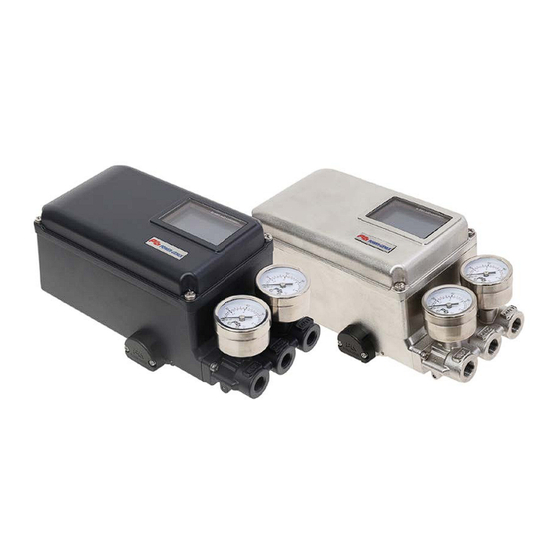
- Page 1 Instruction and Operating Manual Smart Valve Positioner ASD-5000 Series Power-Genex Ltd. ver 1.0...
-
Page 2: Table Of Contents
ASD-5000 Series Contents Overview of Structure ................................9 Technical data ..................................10 How to order code ................................11 4.1. Descriptions on Nameplate ..........................12 Principle of Operation ............................... 12 Descriptions of LCD Display and Buttons ........................ 13 6.1. LCD Display ................................14 6.1.1. - Page 3 ASD-5000 Series 9.4. Wiring for Intrinsic Safety ........................... 28 9.4.1. Input signal (4-20mA @ VDC)......................28 9.4.2. Output signal (24VDC) ..........................28 9.4.3. Alarm limit (24VDC) ..........................29 9.4.4. 2 x SPDT ................................. 29 9.4.5. 2 x P&F, SJ2-SN ............................30 9.5.
- Page 4 3. Before machinery/equipment is restarted, take measures to prevent unexpected operation and malfunction. 4. Contact POWER-GENEX beforehand and take special consideration of safety measures if the product is to be used in any of the following conditions. 1. Conditions and environments outside of the given specifications, or use outdoors or in a place exposed to direct sunlight.
- Page 5 Deterioration of rubber materials are not covered by the limited warranty. Compliance Requirements 1. The use of POWER-GENEX products with production equipment for the manufacture of weapons of mass destruction (WMD) or any other weapon is strictly prohibited. 2. The exports of POWER-GENEX products or technology from one country to another are governed by the relevant security laws and regulations of the countries involved in the transaction.
- Page 6 ASD-5000 Series 1-3 Precautions Be sure to read before handling. Operation Warning 1. Do not operate the positioner outside the specified range as this may cause problems. (Refer to the specifications.) 2. Design the system to include a safety circuit to avoid the risk of danger should the positioner suffer failure.
- Page 7 ASD-5000 Series 1-4 Precautions Be sure to read before handling. Handling Caution 1. Avoid excessive vibration or impact to the positioner body and any excessive force to the armature, as these actions may cause damage to the product. Handle carefully while transporting and operating.
- Page 8 ASD-5000 Series 1-5 Precautions Be sure to read before handling. Maintenance Warning 1. After installation, repair or disassembly, connect compressed air and conduct tests to confirm appropriate function and leakage. Do not use the positioner when noise from the bleeder sounds louder compared with the initial state, or when it does not operate normally.
-
Page 9: Overview Of Structure
ASD-5000 Series Overview of Structure ASD-5000 positioner consists of the following parts. • Electronic card with microprocessor, HART modem and LCD • MPS for position feedback • Pilot valve, torque motor, pressure gauge and block Names of External Parts PCB Cover... -
Page 10: Technical Data
ASD-5000 Series Technical data 1. Input 6. Enclosure Standard Material : Aluminum die-cast + Epoxy painted Supply power : 4 to 20mA, Loop powered 316 Stainless steel housing Max. : 50mA Protection class : IP66 Min. : 3.6mA Pneumatic connections :... -
Page 11: How To Order Code
ASD-5000 Series How to order code Model classification code or ordering information or type designation or model schedule or model numbering system ① ② ③ ④ ⑤ ⑥ ⑦ ⑧ ⑨ ⑩ ⑪ ⑫ ⑬ ⑭ ASD-5 Series positioner ASD - 5... -
Page 12: Descriptions On Nameplate
ASD-5000 Series 4.1. Descriptions on Nameplate Model No: Model number and options are described. Input signal: Current input signal is described. 4~20mA current is used. Inquire the head office or the agents if other special input signal is required. -
Page 13: Descriptions Of Lcd Display And Buttons
ASD-5000 Series If 4-20 mA input signal is supplied, the micro-processor compares input signal with position feedback and sends control signal to the I/P converting module. Pneumatic signal from the I/P converting module operates the valve and the valve stays at the desired position. -
Page 14: Lcd Display
ASD-5000 Series 6.1. LCD Display 6.1.1. Modes of Display Focusing on target value and present value Focusing on present value (basic display) Showing all data After rotated by 90 / 270° Showing TV and PV by graph showing trend deviation (±5%) 6.1.2. -
Page 15: Installation
ASD-5000 Series Installation Be sure to install the air filter regulator before the positioner and check a supply air pressure required to move the valve. 7.1. Mounting onto Linear Actuator 7.1.1. Installation of Follower Guide ① Follower guide ② Clamp plate ③... -
Page 16: Mounting Onto Cast Yoke Or Pillar Yoke
ASD-5000 Series 7.1.3. Mounting onto Cast Yoke or Pillar Yoke < Cast yoke type > < Pillar yoke type > ① Cast yoke ② Mounting bracket ③ Screws(M8) ④ U-bolts ⑤ Pillar yoke 7.1.4. Mounting on Other Kind of Cast Yoke <... -
Page 17: Mounting On Diaphragm Actuator
ASD-5000 Series 7.1.5. Mounting on Diaphragm Actuator Feedback Levers "B" type: 8 ~ 70mm stroke "C" type: 8 ~ 130mm stroke 7.1.6. Installation of Feedback Pin Follower Guide www.powergenex.com... -
Page 18: Standard Installation
ASD-5000 Series 7.1.7. Standard Installation ① Supply air directly to the actuator, adjust the air filter regulator and set air when the valve reaches to 50% stroke. ② Install the feedback pin at around 30% higher point of the stroke indicated on the feedback lever than the required stroke of the control valve and fix with a screw tightly. -
Page 19: Operating Angle
ASD-5000 Series 7.1.8. Operating Angle 7.1.9. Proper Installation of Valve stem pin on Feedback Lever 7.1.10. Proper Directions of Installation www.powergenex.com... -
Page 20: Mounting Onto Rotary Actuator
ASD-5000 Series 7.2. Mounting onto Rotary Actuator 7.2.1. The ASD-5000 positioner supports NAMUR mounting standard (VDI/VDE 3835, IEC 60534-6- ① ASD-5000 positioner ② Multi-size bracket ③ Rotary pneumatic actuator Assemble the multi-size bracket to the ASD-5000 positioner with 4 pcs M6 screw. The ... -
Page 21: Mounting With Fork Lever Type
ASD-5000 Series 7.2.2. Mounting with Fork Lever Type ① ASD-5000 positioner ② Multi-size bracket ③ Rotary pneumatic actuator ④ Fork lever ⑤ Positioner feedback lever 7.2.3. Position of Fork Lever Clockwise movement Counter-clockwise Movement www.powergenex.com... -
Page 22: Re-Assembling Multi-Size Bracket According To Rotary Actuator
ASD-5000 Series 7.2.4. Re-assembling Multi-size Bracket according to Rotary Actuator (mm) (mm) (mm) (mm) Check L and H on the actuator and re-assemble the multi-size bracket to fit your actuator mounting configuration. www.powergenex.com... -
Page 23: Air Connections
ASD-5000 Series Air Connections ① Be sure to install the air filter regulator before the positioner. ② Supply air should not contain water, oil or moisture. ③ It is recommended to set a supply air pressure 10% higher than the actual operating Pressure of the actuator. -
Page 24: Asd-5000 (Rotary Type)
ASD-5000 Series 8.2. ASD-5000 (rotary type) Spring return Double Acting Double Acting As input signal increases, As input signal increases, As input signal increases, actuator shaft rotates actuator shaft rotates actuator shaft rotates counter-clockwise counter-clockwise clockwise Actuator : RA Actuator : RA Actuator : DA 8.3. -
Page 25: Electrical Connections
ASD-5000 Series Electrical Connections ① Be sure to supply the rated voltage and current stated on this manual. Otherwise, it may cause a serious damage or malfunctions. ② Check polarity of + and – exactly and connect wires. ③ When it is necessary to open the positioner cover at a humid place, more attention is required. -
Page 26: Wiring
ASD-5000 Series 9.2. Wiring 9.2.1. Input signal and Output signal Output signal Transmitter load limitation Zero and span of position feedback (4-20mA output signal) are set automatically during auto-calibration process. 9.2.2. Alarm limit (Wet contact) 24VDC should be supplied for software limit switches. -
Page 27: Limit Switch (Dry Contact)
ASD-5000 Series 9.2.3. Limit switch (Dry contact) 9.2.4. Proximity sensor (P&F, SJ2-SN) 9.3. Earthing The earthing of enclosure is necessary to maintain Intrinsic safety because the insulation between an intrinsically safe circuit and a frame of the equipment is not capable of withstanding a 500V dielectric strength test. -
Page 28: Wiring For Intrinsic Safety
ASD-5000 Series 9.4. Wiring for Intrinsic Safety The ASD-5 positioner is designed to meet the intrinsic safety standards of IEC/EN 60079-0, IEC/EN 60079-11, EN 13463-1, EN 13463-5. But the ASD-5 positioner can be affected by the electrical or magnetic energy from other electric products. So please make a note of the instructions below. -
Page 29: Alarm Limit (24Vdc)
ASD-5000 Series 9.4.3. Alarm limit (24VDC) Terminal No. Alarm 1(Low) : 11(+), 12(-) Alarm 2(high) : 14(+), 15(-) Safety parameters : Ui ≤ 28Vdc, Ii ≤ 93mA, Pi ≤ 651mW, Li = 0, Ci = 0nF 9.4.4. 2 x SPDT Terminal No. -
Page 30: P&F, Sj2-Sn
ASD-5000 Series 9.4.5. 2 x P&F, SJ2-SN Terminal No. P&F sensor 1(lower) : 11(+), 12(-) P&F sensor 2(upper) : 14(+), 15(-) Safety parameters : Ui ≤ 16Vdc, Ii ≤ 25mA, Pi ≤ 64mW, Li ≤ 100μH, Ci ≤ 30nF www.powergenex.com... -
Page 31: Cable Gland / Blind Plug
ASD-5000 Series 9.5. Cable Gland / Blind Plug 9.5.1. Cable Gland 1. Cable Gland Cover 2. Cable Gland Sealing 3. Cable Gland Body 4. Blind Plug 1. The cable gland is installed as above before delivery. Change the positions of the cable gland and the blind plug for installation on other side. - Page 32 ASD-5000 Series Quick Auto-Calibration 10.1. 퀵 오토 캘리브레이션 입력신호 공급후 MODE 버튼을 약 5 초 동안 누르면 오토-켈리브레이션이 바로 진행됩니다. DIRECTION : 회전방향 CCW – RA, CW – DA MODE 버튼을 5 초간 눌러준다 CENTER : 중간 각도의 벗어난 정도를 표기...
- Page 33 ASD-5000 Series Description of Parameters Flow 11.1. Diagram of Parameters www.powergenex.com...
- Page 34 ASD-5000 Series < Language : 한국어 > www.powergenex.com...
- Page 35 ASD-5000 Series < Language : 中文 > www.powergenex.com...
- Page 36 ASD-5000 Series 11.2. Main Parameters Ref. Parameter Description Function DISPLAY VARIABLE DISPLAY changes the LCD display mode PV % PV % value shows the current position by % 11.4.2 shows the current position by % in a reverse way PV-REV % PV-Reversed % value ( Ex.
- Page 37 ASD-5000 Series 11.3. Parameters 11.3.1. Main Parameters Ref. Parameter Description Function Default 11.5.1 INPUT Input signal 4…20mA or 20…4mA 4…20mA 11.5.2 REV/DIR ACTION RA / DA Reverse acting or direct acting Auto-set Linear, Shape mode, 11.5.3 LIN/SHAPE/USER Characteristic Linear or User set (17points) 11.5.4...
- Page 38 ASD-5000 Series 11.4. Setting of Main Parameters 11.4.1. [LOCK] LOCK ON / OFF MODE MODE MODE DISPLAY VARIABLE LOCK DISPLAY VARIABLE MANUAL MANUAL MONITORING MONITORING AUTO TUNE AUTO → → PARAMETERS PARAMETERS TEST TEST LOCK LOCK [LOCK]은 포지셔너의 기능을 조작하지 못하도록 설정하는 기능입니다.
- Page 39 ASD-5000 Series 11.4.3. Manual Mode MODE MODE MODE DISPLAY VARIABLE MANUAL MANUAL MANUAL MANUAL SET MANUAL SET MONITORING → 25.0% COMMAND AUTO TUNE → PARAMETERS 25.0% TEST UP&DN 버튼으로 0.1%씩 조정이 가능합니다. 버튼 조작을 이용하여 수동으로 밸브를 조작하는 기능입니다. 기능을 이용하여 시운전 및 임의 동작이 필요한 경우 외부 신호와 상관없이 조작이 가능합니다.
- Page 40 ASD-5000 Series 11.4.5. [AUTO] Auto-Calibration Mode MODE MODE DISPLAY VARIABLE AUTO TUNE MANUAL AUTO CALIBRATION MONITORING PARA. RESET AUTO TUNE START & END CAL. → PARAMETERS COLD START TEST 켈리브레이션 , 공장 초기화 , 재시작을 실행하는 메뉴입니다. 켈리브레이션은 두가지 방식이 있으며, 켈리브레이션 내용은 아래와 같습니다.
- Page 41 ASD-5000 Series 11.4.5.B Initializing Setting Values (RESET) MODE MODE DISPLAY VARIABLE AUTO TUNE MANUAL AUTO CALIBRATION MONITORING PARA. RESET AUTO TUNE START & END CAL. → PARAMETERS COLD START TEST All setting values return to the standard factory setting values.
- Page 42 ASD-5000 Series 11.4.6. Test Mode 11.4.6.A [VALVE TEST] MODE MODE MODE DISPLAY VARIABLE TEST TEST MANUAL VALVE TEST VALVE TEST MONITORING INSTALL CHECK SET COMMAND AUTO TUNE → → PARAMETERS TEST MODE MODE MODE TEST TEST TEST VALVE TEST VALVE TEST...
- Page 43 ASD-5000 Series 11.4.6.B [INSTALL CHECK] MODE MODE MODE DISPLAY VARIABLE TEST TEST MANUAL VALVE TEST INSTALL CHECK MONITORING INSTALL CHECK 25.0 deg AUTO TUNE → → PARAMETERS TEST MODE MODE MODE TEST TEST TEST Intall INSTALL CHECK INSTALL CHECK INSTALL CHECK Fault 25.0 deg...
- Page 44 ASD-5000 Series 11.5. Parameters Flow Diagram www.powergenex.com...
- Page 45 ASD-5000 Series 11.5.1. [INPUT] Change of Input signal (default: 4-20mA) MODE MODE MODE DISPLAY VARIABLE PARAMETERS PARAMETERS MANUAL INPUT INPUT MONITORING REV/DIR ACTION 4~20mA AUTO TUNE LIN/SHAPE/USER 20~4mA PARAMETERS SPAN TEST ZERO UP MODE MODE DISPLAY VARIABLE DISPLAY VARIABLE INPUT...
- Page 46 ASD-5000 Series 11.5.3. [LIN/SHAPE/USER] Selection of Linear, Shape or User Set (default: LINEAR) MODE MODE MODE DISPLAY VARIABLE PARAMETERS PARAMETERS MANUAL INPUT LIN/SHAPE/USER MONITORING REV/DIR ACTION LINEAR AUTO TUNE LIN/SHAPE/USER SHAPE MODE PARAMETERS SPAN USER TEST ZERO UP MODE MODE...
- Page 47 ASD-5000 Series 11.5.3.C [USER] User characteristic MODE MODE MODE PARAMETERS PARAMETERS PARAMETERS LIN/SHAPE/USER LIN/SHAPE/USER LIN/SHAPE/USER LINEAR USER USER SHAPE MODE USER 0.0 % 4mA – 20mA 까지 1mA 마다 위치 값을 조정하여 사용자가 원하는 제어 곡선을 만들 수 있습니다. Example 1)
- Page 48 ASD-5000 Series 11.5.4. [SPAN] Span Adjustment (default: 100.0) MODE MODE MODE DISPLAY VARIABLE PARAMETERS PARAMETERS MANUAL INPUT SPAN MONITORING REV/DIR ACTION 100.0 % AUTO TUNE LIN/SHAPE/USER PARAMETERS SPAN TEST ZERO UP MODE MODE DISPLAY VARIABLE DISPLAY VARIABLE INPUT MANUAL REV/DIR ACTION...
- Page 49 ASD-5000 Series 11.5.6. [DEADBAND] Setting of Dead Band (default: 0.3) MODE MODE MODE DISPLAY VARIABLE PARAMETERS PARAMETERS MANUAL REV/DIR ACTION DEADBAND MONITORING LIN/SHAPE/USER 0.3 % AUTO TUNE SPAN PARAMETERS ZERO UP TEST DEADBAND MODE MODE DISPLAY VARIABLE DISPLAY VARIABLE REV/DIR ACTION...
- Page 50 ASD-5000 Series 11.5.7. PID-Gain MODE MODE MODE DISPLAY VARIABLE PARAMETERS PARAMETERS MANUAL LIN/SHAPE/USER MONITORING SPAN P-Gain AUTO TUNE ZERO UP I-Gain PARAMETERS DEADBAND D-Gain TEST 포지셔너 제어에 필요한 PID 제어 값을 조정하는 파라메터 입니다. 일반적인 상황에서는 별도의 조작이 필요 없으며, 밸브의 헌팅 및 오실레이션이 발생되는 경우...
- Page 51 ASD-5000 Series 11.5.7.C D-Gain (Differential Gain) MODE MODE MODE PARAMETERS PARAMETERS PARAMETERS P-Gain D-Gain P-Gain I-Gain I-Gain D-Gain D-Gain As D-Gain is set automatically during auto-calibration process, it is not necessary to change manually. D-gain 은 미분적분을 하는 파라메터로 오버슛 및 언더슛이 발생되지 않도록 제어값을 감소...
- Page 52 ASD-5000 Series 11.5.8. [CTRL] – Control Speed Adjustment MODE MODE MODE DISPLAY VARIABLE PARAMETERS PARAMETERS MANUAL SPAN CONTROL MONITORING ZERO UP SPEED AUTO TUNE DEADBAND 1ST DAMPING PARAMETERS 2ST DAMPING TEST CONTROL SENSITIVITIY LEVER COMP . LINEARIZATION 11.5.8.A [SPEED] – Response Speed Adjustment (default: 995)
- Page 53 ASD-5000 Series 11.5.8.B [1ST DAMPING] – 1 Damping Limit (default: automatically-set) MODE MODE MODE PARAMETERS PARAMETERS PARAMETERS CONTROL CONTROL CONTROL SPEED 1ST DAMPING SPEED 1ST DAMPING 1ST DAMPING 2ND DAMPING 2ND DAMPING SENSITIVITIY SENSITIVITIY Damping is to limit a control range and set automatically during an auto-calibration process.
- Page 54 ASD-5000 Series 11.5.8.D [SENSITIVITIY] – Setting of Sensitivity (default: MIDDLE) MODE MODE MODE PARAMETERS PARAMETERS PARAMETERS CONTROL CONTROL CONTROL SPEED SENSITIVITIY SPEED 1ST DAMPING 1ST DAMPING 2ND DAMPING MIDDLE 2ND DAMPING SENSITIVITIY HIGH SENSITIVITIY This is to set a sensitivity of positioner. For a more stable control, set to HIGH with a big actuator and to LOW with a small actuator.
- Page 55 ASD-5000 Series 11.5.8.F [LINEARIZATION] MODE MODE MODE PARAMETERS PARAMETERS PARAMETERS CONTROL CONTROL CONTROL 2ND DAMPING LINEARIZATION LINEARIZATION SENSITIVITIY LINZ 25% LINZ 25% LEVER COMP. LINZ 50% 25.0% LINEARIZATION LINZ 75% 선형화 보상 파라메터로, 25%구간씩 위치 값으로 보상하여 보다 정밀한 제어를 할 수 있도록...
- Page 56 ASD-5000 Series 11.5.9. SUB Parameter MODE MODE MODE DISPLAY VARIABLE PARAMETERS PARAMETERS MANUAL ZERO UP SUB MENU MONITORING DEADBAND FULL CLOSE AUTO TUNE FULL OPEN PARAMETERS CONTROL OUTPUT mA TEST SUB MENU SPLIT LCD ROTATION ALARM INPUT CAL. OUTPUT CAL.
- Page 57 ASD-5000 Series 11.5.9.A [FULL CLOSE] Valve Shut-off Control (default: 0.5) MODE MODE MODE PARAMETERS PARAMETERS PARAMETERS SUB MENU SUB MENU SUB MENU FULL CLOSE FULL CLOSE FULL CLOSE FULL OPEN 0.5 % FULL OPEN OUTPUT mA OUTPUT mA SPLIT SPLIT It is a safety function to close a valve completely.
- Page 58 ASD-5000 Series 11.5.9.C [OUT] Setting of Output Signal (default: 4 - 20mA) MODE MODE MODE PARAMETERS PARAMETERS PARAMETERS SUB MENU SUB MENU SUB MENU FULL CLOSE OUTPUT mA FULL CLOSE FULL OPEN 4~20mA FULL OPEN OUTPUT mA 20~4mA OUTPUT mA...
- Page 59 ASD-5000 Series 11.5.9.E [LCD ROTATION] Rotation of Display Position on LCD MODE MODE MODE PARAMETERS PARAMETERS PARAMETERS SUB MENU SUB MENU SUB MENU FULL OPEN LCD ROTATION FULL OPEN OUTPUT mA 0 Degree OUTPUT mA SPLIT 90 Degree SPLIT LCD ROTATION...
- Page 60 ASD-5000 Series 11.5.9.F [ALARM] Setting of 24VDC Software Limit Switches (default: 0 – 10%, 90 – 105%) MODE MODE MODE PARAMETERS PARAMETERS PARAMETERS SUB MENU SUB MENU SUB MENU OUTPUT mA ALARM ALARM SPLIT ALARM1 LOW ALARM1 LOW LCD ROTATION ALARM1 HIGH 0.0 %...
- Page 61 ASD-5000 Series 11.5.9.G [INPUT CAL.] – Setting of Input Signal (default: factory setting) MODE MODE MODE PARAMETERS PARAMETERS PARAMETERS SUB MENU SUB MENU SUB MENU SPLIT INPUT CAL. INPUT CAL. LCD ROTATION IN 4mA IN 4mA ALARM IN 20mA INPUT CAL.
- Page 62 ASD-5000 Series [HART ADDRESS] – HART Communication Address (default: 0) (Option : HART) 11.5.9.I MODE MODE MODE PARAMETERS PARAMETERS PARAMETERS SUB MENU SUB MENU SUB MENU ALARM HART ADDRESS ALARM INPUT CAL. INPUT CAL. OUTPUT CAL. OUTPUT CAL. HART ADDRESS HART ADDRESS This is to select one of HART communication polling address (0 ~ 15) on site.
- Page 63 ASD-5000 Series 11.5.9.K [PST] – Partial Stroke Testing (default: OFF) MODE MODE PARAMETERS PARAMETERS SUB MENU SUB MENU INPUT CAL. OUTPUT CAL. HART ADDRESS [CYCLE TIME] : TEST time interval (default: 24Hr) - Setting of ‘0Hr’ shows the PST working status every 1 minute.
- Page 64 ASD-5000 Series [RESPONSE] : Waiting time that the valve follows after the test signal (default: ‘10’ seconds) MODE MODE MODE PARAMETERS PARAMETERS PARAMETERS SUB MENU SUB MENU SUB MENU CYCLE TIME RESPONSE COMMAND SET 10 Sec RAMP 5, 15, 20, 30 Sec RESPONSE Even though ‘Good’...
- Page 65 ASD-5000 Series [PRESSURE] – Pressure sensor (default: Auto)(Option : Advanced diagnostics) 11.5.9.L MODE MODE MODE PARAMETERS PARAMETERS PARAMETERS SUB MENU SUB MENU SUB MENU OUTPUT CAL. PRESSURE PRESSURE HART ADDRESS SUPPLY SUPPLY OUT1 PRESSURE OUT2 Advanced diagnostics 기능을 추가하면 4 개의 pressure sensor 가 내장되며, 측정된 값을...
-
Page 66: Maintenance / Service
ASD-5000 Series Maintenance / Service 12.1. Preliminary Check Points 12.1.1. Voltage - The positioner commonly requires 4-20mA @ 24VDC for operation. - Voltage drop (impedance): Without HART – 6.8VDC (340Ω @ 20mA) With HART – 7.8VDC (390Ω @ 20mA) With HART+Advanced diagnostics –... - Page 67 ASD-5000 Series 12.4 Exchanging the Positioner Spare Parts ① Begin procedure after complete removal of supply air. ② Re-start auto-calibration procedure after exchanging spare parts 12.4.1 How to Exchange ASD-5000 Pilot Valve ① Disassemble the Pilot valve cover. ② Disassemble the fixing bolts (4EA) after removing the pilot valve cover ③...
-
Page 68: Spare Parts
ASD-5000 Series Parts list List of Spare Parts Part No. Description PG-ASD-7000-01 Main Body PG-ASD-7000-02 Main Cover PG-ASD-7000-03 Airline Body PG-ASD-7000-04 Auto / Manual screw PG-ASD-7000-05 Gauge Block PG-ASD-7000-06 Gauge PG-ASD-7000-07 Pilot Valve PG-ASD-7000-08 Torque motor Coil PG-ASD-7000-09 Board Cover... -
Page 69: Dimensions
ASD-5000 Series Dimensions 14.1. ASD-5000 (linear type) www.powergenex.com... -
Page 70: Asd-5000 (Rotary Type)
ASD-5000 Series 14.2. ASD-5000 (rotary type) www.powergenex.com... - Page 71 - In case that the products are damaged by fire, earthquake, storm, flood, thunder, lighting, other natural disasters, riot, war, exposure to radioactivity 4. If maintenance is required, please contact distributors or Power-Genex directly. A proper and satisfactory customer service will be provided.
Need help?
Do you have a question about the ASD-5000 Series and is the answer not in the manual?
Questions and answers