
Related Manuals for Power-Genex SS2L Series


Summary of Contents for Power-Genex SS2L Series
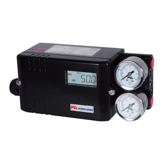
- Page 1 Instruction and Operating Manual Smart Valve Positioner SS2L / SS2R Series SS2SL / SS2SR Series (SS316) <Software Version 4.11> Power-Genex Ltd.
-
Page 2: Table Of Contents
SS2L / SS2R Series C o n t e n t s 1. Safety Instructions / Precautions 2. Overview of Structure 3. Specifications 3.1 Specifications of Profibus PA Communication 3.2 Specifications of Fieldbus Communication 4. Part Numbering System (Order Code) 5. - Page 3 SS2L / SS2R Series 11.5.1 Change of Input Signal 11.5.2 ] Selection of Direct Acting or Reverse Acting 11.5.3 Selection of Linear, E.Q.%, Quick Open, User Set (17points) 11.5.4 Span Adjustment 11.5.5 Zero Adjustment 11.5.6 PID-Gain 11.5.6.A P-Gain 11.5.6.B I-Gain 11.5.6.C D-Gain 11.5.6.D GROP-Gain 11.5.7 Control Speed adjustment...
-
Page 4: Safety Instructions / Precautions
3. Before machinery/equipment is restarted, take measures to prevent unexpected operation and malfunction. 4. Contact POWER-GENEX beforehand and take special consideration of safety measures if the product is to be used in any of the following conditions. 1. Conditions and environments outside of the given specifications, or use outdoors or in a place exposed to direct sunlight. - Page 5 Compliance Requirements 1. The use of POWER-GENEX products with production equipment for the manufacture of weapons of mass destruction (WMD) or any other weapon is strictly prohibited. 2. The exports of POWER-GENEX products or technology from one country to another are governed by the relevant security laws and regulations of the countries involved in the transaction.
- Page 6 SS2L / SS2R Series 1-3 Precautions Be sure to read before handling. Operation Warning 1. Do not operate the positioner outside the specified range as this may cause problems. (Refer to the specifications.) 2. Design the system to include a safety circuit to avoid the risk of danger should the positioner suffer failure.
- Page 7 SS2L / SS2R Series 1-4 Precautions Be sure to read before handling. Handling Caution 1. Avoid excessive vibration or impact to the positioner body and any excessive force to the armature, as these actions may cause damage to the product. Handle carefully while transporting and operating.
- Page 8 SS2L / SS2R Series 1-5 Precautions Be sure to read before handling. Maintenance Warning 1. After installation, repair or disassembly, connect compressed air and conduct tests to confirm appropriate function and leakage. Do not use the positioner when noise from the bleeder sounds louder compared with the initial state, or when it does not operate normally.
-
Page 9: Overview Of Structure
SS2L / SS2R Series 2. Overview of Structure This product consists of the following parts. • Electronic card comprised of microprocessor, HART modem and LCD • Potentiometer for position feedback • Gauge block Description The followings are descriptions of internal parts without cover. Board cover Gauge block Supply air gauge... -
Page 10: Specifications
SS2L / SS2R Series 3. Specifications Input signal 4 - 20 mA @ 24 VDC Min. / Max. current 3.6 mA / 50mA Communication HART / Profibus PA / Foundation Fieldbus Linear type: 5 - 130mm * Operating angle/ stroke Rotary type: 25 - 120°... -
Page 11: Specifications Of Profibus Pa Communication
SS2L / SS2R Series Current Consumption 15 mA 16 mA Voltage drop 8.9 VDC 9.4 VDC (impedance) (445Ω @ 20mA) (470Ω @ 20mA) * For more than 200mm stroke on request ** Operating temperature of -40℃ on request 3.1 Specifications for Profibus PA Communication Profiles PROFIBUS Profile for Process Control Devices Version 3.02 1 AI Function Block... - Page 12 SS2L / SS2R Series Transmission rate 31.25 kbit/s Supply voltage Bus-powered : 9 ~ 32 VDC 2 AI Function Block 1 AO Function Block Block types 2 DI Function Block 1 Transducer Block 1 Physical Block Max. execution time AO block: 31.25 milliseconds Supply voltage Power feed from the fieldbus: 9 ~ 32 VDC Max.
-
Page 13: Part Numbering System (Order Code)
SS2L / SS2R Series 4. Part Numbering System (order code) SS2 x — Body material Aluminum die-cast Stainless steel 316 Actuator type Linear Rotary Protection class Intrinsically safe (Exia IIC T6/T5) Weatherproof to IP66 Feedback lever Linear type 5 ~ 30mm stroke 5 ~ 70mm stroke 5 ~ 130mm stroke 80 ~ 200mm stroke... -
Page 14: Principle Of Operation
SS2L / SS2R Series 4.1 Descriptions on Nameplate ᆢ Model No.: The product model and options selected are described. ᆢ Input signal: 4 – 20mA input signal with 2-wire is described. ᆢ Ambient Temp.: The ambient temperate range for operation is described. ᆢ... -
Page 15: Descriptions Of Lcd Display And Buttons
SS2L / SS2R Series 6. Descriptions of LCD display and Buttons ① Display of input or output ② Main parameters ③ mA, % display mode ④ Operation of HART ⑤ Up button ⑥ Down button ⑦ Mode button ⑧ Enter button Press "Mode"... -
Page 16: Installation
SS2L / SS2R Series 7. Installation Be sure to install the air filter regulator before the positioner and check a supply air pressure required to move the valve. 7.1 Mounting onto Linear Actuator 7.1.1 Installation of Follower Guide ① Follower guide ②... - Page 17 SS2L / SS2R Series 7.1.3 Mounting onto Cast Yoke or Pillar Yoke < Cast yoke type > < Pillar yoke type > ① Cast yoke ② Mounting bracket ③ Screws(M8) ④ U-bolts ⑤ Pillar yoke 7.1.4 Mounting onto Other Kind of Cast Yoke ①...
- Page 18 SS2L / SS2R Series 7.1.5. Mounting on Diaphragm Actuator Feedback Levers "A" type: 8 ~ 30mm stroke "B" type: 8 ~ 70mm stroke "C" type: 8 ~ 130mm stroke "D" type: 80 ~ 200mm stroke 7.1.6 Installation of Feedback Pin Follower Guide www.powergenex.com...
- Page 19 SS2L / SS2R Series 7.1.7 Standard Installation ① Supply air directly to the actuator, adjust the air filter regulator and set air when the valve reaches to 50% stroke. ② Install the feedback pin at around 30% higher point of the stroke indicated on the feedback lever than the required stroke of the control valve and fix with a screw tightly.
- Page 20 SS2L / SS2R Series <Maximum operating ange : 60°> <Indicator position at 50%> <Indicator position at 0% (100%)> <Indicator position at 100% (0%)> www.powergenex.com...
-
Page 21: Mounting Onto Rotary Actuator
SS2L / SS2R Series 7.2 Mounting onto Rotary Actuator 7.2.1 The SS2R positioner supports NAMUR mounting standard (VDI/VDE 3835, IEC 60534-6-2). ① SS2R positioner ② Multi-size bracket ③ Rotary pneumatic actuator ⓐ Assemble the multi-size bracket to the SS2R positioner with 4 pcs M6 screw. The multi-size bracket is assembled for 80x30x20mm as standard at the factory. - Page 22 SS2L / SS2R Series <Indicator position at 0% (or 100%)> <Indicator position at 100% (0%)> 7.2.2 Mounting with Fork Lever Type ① SS2R positioner ② Multi-size bracket ③ Rotary pneumatic actuator ④ Fork lever ⑤ Positioner feedback lever 7.2.3 Position of Fork Lever Clockwise movement Counter-clockwise Movement www.powergenex.com...
- Page 23 SS2L / SS2R Series 7.2.4 Re-assembling Multi-size Bracket according to Rotary Actuator (mm) (mm) (mm) (mm) Check L and H on the actuator and re-assemble the multi-size bracket to fit your actuator mounting configuration. www.powergenex.com...
-
Page 24: Air Connections
SS2L / SS2R Series 8. Air Connections ① Be sure to install the air filter regulator before the positioner. ② Supply air should not contain water, oil or moisture. ③ It is recommended to set a supply air pressure 10% higher than the actual operating pressure of the actuator. -
Page 25: Electrical Connections
SS2L / SS2R Series 9. Electrical Connections ① Be sure to supply the rated voltage and current stated on this manual. Otherwise, it may cause a serious damage or malfunctions. ② Check polarity of + and – exactly and connect wires. ③... -
Page 26: Measuring Output Signal
SS2L / SS2R Series 9.2 Measuring Output Signal 9.2.1 With mA loop calibrator Position Transmitter Specifications Output signal 4 – 20mA, 2-wire Power supply 12 – 30 VDC Output current limit 30mA DC 9.2.2 With multi-meter Linearity ±0.75% F.S Operating temperature -20 ~ +80℃... -
Page 27: Wiring Spdt Micro Switches
SS2L / SS2R Series 9.6 Wiring SPDT Micro Switches Micro Switch Specifications Type SPDT Rating code 10.1A @ 250 VAC Operating temperature -25 ~ +85℃ 9.7 Setting Micro Switches After auto-calibration process, turn the micro switch cams clockwise slowly and check the contact points. -
Page 28: Wiring For Intrinsic Safety
SS2L / SS2R Series 9.9 Wiring for Intrinsic Safety The SS2L / SS2R positioner is designed to meet the intrinsic safety standards of IEC/EN 60079-0, IEC/EN 60079-11, EN 13463-1, EN 13463-5. But the SS2L / SS2R positioner can be affected by the electrical or magnetic energy from other electric products. -
Page 29: Cable Gland / Blind Plug
SS2L / SS2R Series 9.10 Cable Gland / Blind Plug 9.10.1 Cable Gland 1. Cable Gland Cover 2. Cable Gland Sealing 3. Cable Gland Body 4. Blind Plug 1. The cable gland is installed as above before delivery. Change the positions of the cable gland and the blind plug for installation on other side. -
Page 30: Quick Auto-Calibration
SS2L / SS2R Series 10. Quick Auto-Calibration 10.1 Quick Auto-Calibration Supply 4-20mA input signal and push MODE button for 5 seconds, auto-calibration process will start. In case of a reverse acting actuator, RA is displayed and a countdown begins. 5→4→3→2→1→END→RUN (auto-calibration is completed) In case of a direct acting actuator, DA is displayed and a countdown begins. -
Page 31: Description Of Parameters Flow
SS2L / SS2R Series 11. Description of Parameters Flow 11.1 Parameters Flow Diagram Normal RUN Mode Push MODE DISP AUTO PARM TEST LOCK PVPR MSET CHEK TUNE INPU TEST SVMA R/DA MONT PV-R PARA SENT L/EQ ANGL COLD SPAN ZERO CTRL SPED ALRM... -
Page 32: Main Parameters
SS2L / SS2R Series 11.2 Main Parameters Ref. Parameter Description Function DISP DISPLAY changes the LCD display mode PVPR PV % value shows the current position by % 11.4.2 SVMA Input signal mA value shows the input signal by mA (P. -
Page 33: Parameters
SS2L / SS2R Series 11.3 Parameters 11.3.1 Main Parameters Ref. Parameter Description Function Default 11.5.1 (P. 36) INPU Input signal 4…20mA or 20…4mA 4…20mA 11.5.2 (P. 36) R / DA RA / DA Reverse acting or direct acting Linear, E.Q. % (1:25 or 1:50),Quick open L / E.Q / 11.5.3 (P. -
Page 34: Setting Main Parameters
SS2L / SS2R Series 11.4 Setting of Main Parameters The following abbreviations will be used hereafter. MODE ENTER DOWN 11.4.1 LOCK ON / OFF LOCK ① LOCK ON : Saves all setting values. ② LOCK OFF : Be sure to LOCK OFF when it is necessary to read or change the selected parameters and the saved setting values. -
Page 35: Manual Mode
SS2L / SS2R Series 11.4.3 Manual Mode (default: 0) The valve can be moved to 0 – 100% manually. MSET 11.4.4 Monitor Mode CHEK OK 0 ㆍㆍㆍ OK 12 MILE PARA P01 ㆍㆍㆍ P51 ANGL You can check the error codes and a total valve runtime. 11.4.1 MON blinks Select CHEK... -
Page 36: Auto-Calibration Mode
SS2L / SS2R Series 11.4.5 Auto-Calibration Mode AUTO TUNE RSET SENT COLD If necessary, initialize all setting values to the original values set after auto-calibration or return them to the factory setting values. 11.4.5.A Performing Auto-Calibration ① Reverse acting (RA) is a standard factory setting. Even if air lines are connected wrongly by mistake, the SS2 positioner detects automatically and performs auto- calibration for direct acting (DA). -
Page 37: Self-Test Mode
SS2L / SS2R Series 11.4.6 Self-Test Mode TEST MONT • The current valve mounting situation is shown. If the value is far away from 50, the valve will suffer from a poor linearity and hysteresis. Move the positioner and try to reach closer to 50 for the best linearity and hysteresis. -
Page 38: Parameters Flow Diagram
SS2L / SS2R Series 11.5 Parameters Flow Diagram HEVY The colored cells stand for the standard factory settings. All setting values return to the standard factory settings if RESET begins. www.powergenex.com... -
Page 39: Change Of Input Signal
SS2L / SS2R Series 11.5.1 [INPU] Change of Input signal (default: 4-20mA) INPU 4-20 20-4 It is possible to make the positioner respond to 20-4mA input signals optionally even though 4- 20mA input signals are supplied. 11.5.2 [R/DA] Selection of Direct Acting (DA) or Reverse Acting (RA) (default: RA) R/DA 11.5.3 [L/EQ] Change of Linear, E.Q.%, Quick Open or User Set (default: Linear) L/EQ... - Page 40 SS2L / SS2R Series Linear EQ% ( 1 / 25 ) EQ% ( 1 / 50 ) Quick Open User set(17point) - For the user setting, Example 1) User Set Value Ex-1 Ex-2 Input Signal Valve Opening% Point Parameter (mA) (set value) 10MA 10mA...
-
Page 41: Span Adjustment
SS2L / SS2R Series NOTES 1. This user setting has a linear characteristic as standard. 2. 5MA means % corresponding to 5mA. 3. Input all 4MA to 20MA for a required user set characteristic curve. ※ If Shut Off option is set, the set value at 4mA is maintained during interval of the Shut Off setting value as shown in Example 2). The curve goes according the user set value after interval of the Shut Off setting value. -
Page 42: Pid-Gain
SS2L / SS2R Series 11.5.6 PID-Gain P-GN I-GN D-GN GROP ⇕ HIGH MIDD 11.5.6.A P-Gain (Proportional Gain) P-GN Auto Set The micro-processor calculates P-Gain value during auto-calibration process in consideration of sizes of the valve and the actuator. If a hunting problem happens, decrease P-Gain value. If an oscillation problem happens, increase P-Gain value. -
Page 43: D Grop-Gain
SS2L / SS2R Series 11.5.6.B I-Gain (Integral Gain) I-GN Auto Set As I-Gain is set automatically during auto-calibration process, it is not necessary to change manually. 11.5.6.C D-Gain (Differential Gain) D-GN Auto Set As D-Gain is set automatically during auto-calibration process, it is not necessary to change manually. -
Page 44: Control Speed Adjustment
SS2L / SS2R Series 11.5.7 [CTRL] – Control Speed Adjustment CTRL SPED SWST CNLT GCNL SRPS 11.5.7.A [SPED] – Respond Speed Adjustment (default: 1000) SPED 1000 This is to adjust the response speed of the control valve. (Min: 1, Max: 1000) 11.5.7.B [SWST] –... -
Page 45: D Gcnl
SS2L / SS2R Series CNLT is to limit a control range and set automatically during an auto-calibration process. When 0% - 100% input signal is supplied, a recognition range of the positioner is settled according to CNLT. If CNLT is increased as shown in Graph 3, a control speed can become faster but a hunting problem can happen. -
Page 46: Setting Of Dead Band
SS2L / SS2R Series Control the positioner without activating the CONTROL LIMIT mode. Solve a failure of auto-calibration with a big volume actuator. - After setting to 8B perform auto-calibration again. Note that auto-calibration should be performed again after SRPS is set first. 11.5.8 [DEAD] Setting of Dead Band (default: 0.5) DEAD 0-9.99%... -
Page 47: Control Mode
SS2L / SS2R Series 11.5.10 Control Mode according to Valve Working Condition C/MD NORM HARD SMAL HDGP Control Mode is set automatically during auto-calibration. But it can be set manually for the current valve working condition in case of a hunting problem or an overshooting problem. Repleat See 11.5 Select C/MD... -
Page 48: Sub-Parameter
SS2L / SS2R Series 11.5.11 SUB Parameter Ref. Parameter Description Function Default 11.5.11.A Shut-off 0…9.9% 0.3% 11.5.11.B Full-open 0…9.9% 0.3% 11.5.11.C Output signal 4…20mA or 20…4mA 4…20mA 11.5.11.D Split range 4…12mA or 12…20mA 4…20mA Change of Display 11.5.11.E Forward or reverse direction Position on LCD Alarm limit low, 0…10%,... -
Page 49: B Valve Full Open Control
SS2L / SS2R Series 11.5.11.B [FOPN] Valve Full Open Control (default: 0.3) FOPN 0-9.9 The valve can be fully open manually. And it is possible to change 0% to 9.9%. For reference, 0.1% means that the positioner responds to 0.016mA. Therefore, the standard value of 0.3% means that a valve is fully open at 19.952mA. -
Page 50: F Setting Of Alarm Limits
SS2L / SS2R Series 11.5.11.F [ALRM] Setting of Alarm Limits (default: 0 – 10%, 90 – 105%) ALRM AL1L AL1H AL2L AL2H ⇕ ⇕ ⇕ ⇕ 0000 0010 0090 0105 You can set an opening point or a closing point of a control valve. AL1 (L, H) is set to 0 – 10% and AL2 (L, H) is set to 90 –... - Page 51 SS2L / SS2R Series For example, see the below in order to re-set AL2 to 80 – 100%(AL2L = 80, AL2H = 100). ① AL2L Setting ② AL2H Setting How to wire the Alarm Limits 24VDC should be supplied for alarm limits. www.powergenex.com...
-
Page 52: G Setting Of Input Signal
SS2L / SS2R Series 11.5.11.G [ICAL] – Setting of Input Signal (default: factory setting) ICAL IN4M IN20 This is to match 4mA and 20mA input signals from a signal calibrator with the internal setting 0% and 100% of the positioner and save onto memory. If 4mA output signal is measured as 4.2mA and 20mA output signal as 19.8mA with a signal calibrator on site, 4.2mA can be recognized as 0% and 19.8mA as 100% by re-setting with ICAL. -
Page 53: I Hart Polling Address
SS2L / SS2R Series 11.5.11.I [POLL] – HART Communication Polling Address (default: 0) POLL 0 ~ 15 This is to select one of HART communication polling address (0 ~ 15) on site. The default address is “0”. As an unexpected problem can happens during communication, try to select after disconnecting HART communication. -
Page 54: K [Addr] - Manual Setting Of Profibus Pa Address
SS2L / SS2R Series 11.5.11.K [ADDR] – Manual Setting of Profibus PA Address (default: 126) ADDR 1 ~ 125 This is to change the Profibus PA address to 1 – 125 manually on the site. “126” is a factory setting. Select ADDR Change Profibus address... -
Page 55: Re-Setting Of Potentiometer
SS2L / SS2R Series 12.4 Re-setting of Potentiometer (spare part No. 14a, 14b) It is necessary to adjust a setting of potentiometer as below when a gear position is moved due to user’s carelessness. For reference, 0~10kΩ potentiometer is installed into the SS2 positioner. ①... -
Page 56: Troubleshooting
SS2L / SS2R Series 13. Troubleshooting 13.1 Error Codes and Recommended Actions If the positioner doesn’t work properly and on LCD blinks, try to take action as below. DATA DATA blinks Error Cause Symton Action Code Low input current CMLO (3.7mA) Data on LCD are shown too dim or Re-check 4 –... -
Page 57: Checking Diagram For Stable Control
SS2L / SS2R Series 13.2 Checking Diagram for Stable Valve Control NORMAL MODE HARD MODE SMALL MODE Auto-Calibration 4 - 20mA Control test Poor control Hunting Grop-Gain Hard Step 1. (Push UP button 5sec) Oscillation PID-Gain Setting Poor control Step 2. Good control Auto-Control 13.2.1 Judgment of Valve Specifications... -
Page 58: Spare Parts
SS2L / SS2R Series 14. Spare Parts 14.1 SS2L Spare Parts SS2L (LINEAR TYPE) www.powergenex.com... -
Page 59: Ss2R Spare Parts
SS2L / SS2R Series 14.2 SS2R Spare Parts SS2R (ROTARY TYPE) www.powergenex.com... -
Page 60: List Of Spare Parts
SS2L / SS2R Series 14.3 List of Spare Parts Part No. Description S2CO-01 SS2 cover S2BO-03 PCB control board cover BOARD-37 PCB control board module S2BO-08 Pilot valve cover PILOT VALVE-6 Pilot valve module S2BO-06 Body air line cover S2BO-07 Air line O-ring S2BO-01 SS2 body... -
Page 61: Dimensions
SS2L / SS2R Series 15. Dimensions 15.1 SS2L (linear type) www.powergenex.com... -
Page 62: Ss2R(Rotary Type)
SS2L / SS2R Series 15.2 SS2R (rotary type) www.powergenex.com... -
Page 63: Ss2R (2 X Spdt Micro Limit Switch)
SS2L / SS2R Series 15.3 SS2R (with 2 x SPDT micro switch) www.powergenex.com... - Page 64 - In case that the products are damaged by fire, earthquake, storm, flood, thunder, lighting, other natural disasters, riot, war, exposure to radioactivity 4. If maintenance is required, please contact distributors or Power-Genex directly. A proper and satisfactory customer service will be provided.
Need help?
Do you have a question about the SS2L Series and is the answer not in the manual?
Questions and answers
How can I get hart feedback on this ss2L series
To get HART feedback on the Power-Genex SS2L Series, select "H" for the communication option in the part numbering system. This enables HART communication.
This answer is automatically generated