Table of Contents
Advertisement
Quick Links
Advertisement
Table of Contents
Troubleshooting

Related Manuals for Super Products MUD DOG 700

Summary of Contents for Super Products MUD DOG 700
- Page 2 Subject to the terms and conditions below, Super Products warrants to its original purchaser ("original purchaser") that new equipment sold after the effective date of this limited warranty is free of defects in material or workmanship at the time it was shipped from Super Products for a period of 12 months from the shipment date, provided the equipment is used in a normal and reasonable manner and in accordance with all operating instructions.
-
Page 3: Table Of Contents
Plan for Emergency Services......................1 - 14 Job Site Safety and Hazard Warnings - Continued ................1 - 15 Inspect the Job Site........................... 1 - 15 Visibility Conditions When Operating ..................... 1 - 15 Fire Extinguisher ..........................1 - 15 Super Products LLC Publication: 0044321 TOC-1... - Page 4 Decals ..............................1 - 43 Debris Body Tailgate Props ........................1 - 54 Unlocking the Tailgate Props and Raising the Debris Body Tailgate..........1 - 54 Preparation Before Traveling to Worksite ....................1 - 55 TOC-2 Super Products LLC Publication: 0044321...
- Page 5 Preventive Maintenance Instructions ......................4 - 1 Lubrication Recommendation Chart ......................4 - 1 Maintenance Items ............................ 4 - 4 Boom..............................4 - 4 Debris Body............................4 - 4 Electrical System..........................4 - 4 Hydraulic System ..........................4 - 4 Super Products LLC Publication: 0044321 TOC-3...
- Page 6 The Basic Troubleshooting Process ......................5 - 1 Electrical Troubleshooting ........................5 - 7 Winter Recirculation Troubleshooting ....................5 - 14 Hydraulic System ............................ 5 - 15 Electric Block Diagram ........................... 5 - 16 6 Service and Spare Parts 7 Index TOC-4 Super Products LLC Publication: 0044321...
-
Page 7: Safety
Always follow the instruction in this manual and use common sense to avoid hazards Indicates an imminently hazardous situation which, if not avoided, WILL result in death or serious injury. Super Products LLC Publication: 0044321 1-Safety Section 1-1... -
Page 8: Visual Attention Safety
Figure 1-1 NOTE Identifies points of particular interest for more efficient and convenient operation or repair. Translation — Safety Section 130 W Boxhorn Drive Mukwonago, WI 53149 Mukwonago, WI 53149 (800) 837-9711 1-Safety Section 1-2 Super Products LLC Publication: 0044321... -
Page 9: Personal Protection Equipment (Ppe)
Loose clothing can be drawn into the suction hose. Never wear a wristwatch or finger rings when working on or around equipment. Failure to comply could result in serious injury or death. Super Products LLC Publication: 0044321 1-Safety Section 1-3... -
Page 10: When Using Pressurized Air Or Water
When using pressurized air or water for cleaning or material erosion/movement, should following: • Face Shield • Wet Weather Protective Suit • Waterproof Gloves • Respirator • Safety Boots with Metatarsal Guard 1-Safety Section 1-4 Super Products LLC Publication: 0044321... -
Page 11: General Hazards And Prevention Safety
• Keep body and limbs away from suction inlets. • Do not open or close the tailgate or raise or lower the body unless the area is clear of people and obstructions. Super Products LLC Publication: 0044321 1-Safety Section 1-5... -
Page 12: Visibility Conditions When Operating
Replace or repair damaged component immediately. Hot Surface • Stay clear of hot surfaces such as mufflers, hydraulic pumps, valves, and tanks. • Relieve pressure from tank, reservoirs, valves, and hoses before servicing or opening. 1-Safety Section 1-6 Super Products LLC Publication: 0044321... -
Page 13: Crushing Hazards And Prevention Safety
2. Swing body prop support into support position. 3. Slowly lower body tailgate until tailgate contacts tailgate prop support. • To remove tailgate body prop support, reverse above procedure. Super Products LLC Publication: 0044321 1-Safety Section 1-7... - Page 14 Attach only one lanyard per lanyard anchorage point. Face the machine when entering or leaving the • elevated equipment surfaces. • Only mount or dismount when truck and moving parts have completely stopped. 1-Safety Section 1-8 Super Products LLC Publication: 0044321...
- Page 15 Use paper or cardboard to search for leaks. • • Do not use hands or body parts to search for leak. • Keep hands and body away from pin holes and nozzles ejecting hydraulic fluid. Figure 1-9 Super Products LLC Publication: 0044321 1-Safety Section 1-9...
-
Page 16: Power Line/Static Electrical Hazard Warnings
Never get within 10 feet of an overhead power line! • Consider all overhead lines as energized until the electric utility indicates otherwise or an electrician verifies that the line is not energized and has been grounded. 1-Safety Section 1-10 Super Products LLC Publication: 0044321... -
Page 17: Chemical And Biological Hazard Safety
If excessive dust is generated, a dust collection or suppression system should also be used during operation. Super Products LLC Publication: 0044321 1-Safety Section 1-11... -
Page 18: Transport Safety And Hazards Warnings
Use a spotter if you do truck and equipment. not have clear view. • Check for low hanging electric or telephone wires and power cables on the ground. 1-Safety Section 1-12 Super Products LLC Publication: 0044321... -
Page 19: Transport Safety And Hazards Warnings - Continued
Truck has a high center of gravity when carrying a loaded debris body. Use extreme caution when transporting at highway speeds. Slow down for sharp corners to avoid tipping or turning over. Super Products LLC Publication: 0044321 1-Safety Section 1-13... -
Page 20: Job Site Safety And Hazard Warnings
Prepare for Working Near Existing Utilities • Boots must have high tops and meet the electric hazard protection requirements of ASTM F2413 OR ASTMF117, when tested at 14,000 volts. Tuck legs of pants completely inside boots. 1-Safety Section 1-14 Super Products LLC Publication: 0044321... -
Page 21: Job Site Safety And Hazard Warnings - Continued
Do not operate equipment if unsafe but away from possible points of ignition. The fire conditions cannot be controlled. extinguisher should always be classified for both oil and electric fires. It should meet legal and regulatory requirements. Super Products LLC Publication: 0044321 1-Safety Section 1-15... -
Page 22: Vacuum Equipment Operation Safety And Hazard Warnings
Safety Messages. Always use common sense to avoid • Brings truck RPM to idle hazards. • Opens the vacuum relief valve • Shuts off the water pump • All functions remain inactive 1-Safety Section 1-16 Super Products LLC Publication: 0044321... -
Page 23: Vacuum Equipment Operation Safety And Hazard Warnings - Continued
The in-line vacuum relief valve must be in line within 50 feet from the end of the hose or pipe for proper operation. Super Products LLC Publication: 0044321 1-Safety Section 1-17... -
Page 24: Vacuum Equipment Operation Safety And Hazard Warnings - Continued
150°F or higher. Pressurized or pump off loading is not permitted unless the flash point of the material is 150°F or higher, unless nitrogen is present. Figure 1-18 1-Safety Section 1-18 Super Products LLC Publication: 0044321... -
Page 25: Vacuum Relief Valve Safety
(maximum of thirty feet away). If there is more than one operator, there must be a separate T-type valve for each operator. Super Products LLC Publication: 0044321 1-Safety Section 1-19... -
Page 26: Vacuum Relief Valve Safety (Continued)
8. Reset the vacuum relief valve. Remove and store the vacuum relief valve if it is not going to be used. Figure 1-20 Figure 1-19 1-Safety Section 1-20 Super Products LLC Publication: 0044321... -
Page 27: Vacuum Relief Valve Safety (Continued)
1) Vent Open Button 2) Vent Closed Button the vacuum hose may not be able to reach the remote. Figure 1-21 Super Products LLC Publication: 0044321 1-Safety Section 1-21... - Page 28 Never move close to the end of any vacuum hose unless the safety person has the remote pendant and is in a position to observe all operators. Failure to comply could result in serious injury or death. 1-Safety Section 1-22 Super Products LLC Publication: 0044321...
-
Page 29: Testing The Remote-Operated Vacuum Relief Valve
6. After testing, shut down the vacuum pump per operating procedure. Never work beyond the distance from the truck that the wireless remote control was previously tested at. Failure to comply could result in equipment not properly operating. Super Products LLC Publication: 0044321 1-Safety Section 1-23... -
Page 30: High-Pressure Water Safety And Hazard Warnings
Water gun has a kickback when turned on. • Always bleed the pressure from the handgun before disconnecting it from the high-pressure handgun connection. 1-Safety Section 1-24 Super Products LLC Publication: 0044321... -
Page 31: High-Pressure Water Safety And Hazard Warnings - Continued
Be aware of the operating pressures associated with the vehicle and the proper hose specifications for safe operation. Waste Equipment Technology Association publishes a variety of industrial-related information that owners and Super Products LLC Publication: 0044321 1-Safety Section 1-25... -
Page 32: Dust Hazard And Explosion Prevention Safety
• Static charge dissipation • Spark prevention See “Static Charge Dissipation” on page 1-28 and “Spark and Fire Prevention Safety” on page 1-30 for specific information on addressing these two concerns. 1-Safety Section 1-26 Super Products LLC Publication: 0044321... -
Page 33: Hydrocarbon Waste Recovery
300°F without addressing the four concerns. Controlling Lower Explosive Level (LEL) Super Products recommends that a monitor for hazardous hydrocarbon concentrations be installed in the exhaust stream of the vacuum pump to continuously monitor for lower explosive level (LEL). The monitor must... -
Page 34: High-Temperature Prevention
300°F, primary and backup system sensors and air flow modifications to limit operating temperatures should be made to a standard vacuum system as manufactured by Super Products. They include the addition of two temperature gauges with adjustable switches, and two temperature sensors, which should be installed in the exhaust airstream of the vacuum pump. -
Page 35: Static Charge Dissipation
Static Charge Dissipation of the clamp. Wing nuts could assist in making these connections quickly. • Standard Super Products material handling hoses Failure to comply with the recommendations for are specially designed to conduct static electricity. static charge prevention could result in... -
Page 36: Spark And Fire Prevention Safety
The vacuum pump exhaust air should only enter the atmosphere at a minimum of 100 feet away from any other potential ignition source. 1-Safety Section 1-30 Super Products LLC Publication: 0044321... -
Page 37: Debris Body Dumping And Hazard Warnings
In addition, the center of gravity of the debris body is higher with a raised debris body, making the unit more prone to tipping over. Super Products LLC Publication: 0044321 1-Safety Section 1-31... -
Page 38: Sewer Gas Safety And Hazard Warnings
OSHA 3138-01R 2004. The full document can be • Has a limited or restricted means of entry or exit. obtained from www.osha.gov. These spaces may include underground vaults, bodies, storage bins, pits and diked areas, vessels, and silos. 1-Safety Section 1-32 Super Products LLC Publication: 0044321... -
Page 39: Trenching Hazards
SAFETY Trenching Hazards NOTE Reference to OSHA regulations are for informational purposes only and not intended as legal advice. Super Products LLC Publication: 0044321 1-Safety Section 1-33... -
Page 40: De-Energize And Lockout Procedures
“off” position. They provide protection by preventing machines or equipment from becoming energized because they are positive restraints that no one can remove without a key or other unlocking mechanism or through extraordinary means, such as bolt cutters. 1-Safety Section 1-34 Super Products LLC Publication: 0044321... -
Page 41: Hazards With Equipment Maintenance
Follow manufacturer's instructions in handling oils, solvents, cleansers, and other chemical agents. • Do not change any factory-set hydraulic calibrations to avoid component or equipment failures. • Do not modify or alter equipment, functions, or components. Super Products LLC Publication: 0044321 1-Safety Section 1-35... -
Page 42: Decal Location
If any decal provided by Super Products is missing or becomes illegible, a replacement decal can be requested from Super Products at no charge and should be replaced immediately. - Page 43 1-40 Blower Inlet Chamber WARNING 3050-00479 1-38 Rotary Shaft 3.5 x 5.0 DANGER 3050-01179 1-39 Anchor Point WARNING 3050-01222 1-68 Hydraulic Valve Position CAUTION 3050-01286 1-48 Figure 1-33 View of Driver Side Super Products LLC Publication: 0044321 1-Safety Section 1-37...
- Page 44 SAFETY 1-Safety Section 1-38 Super Products LLC Publication: 0044321...
- Page 45 1-63 Boom/Body Valve Manual Overdrive INSTRUCTION 3050-01218 1-51 Anchor Point WARNING 3050-01222 1-68 Cancer and Reproductive Harm WARNING D960 1-62 Transfer Case Oil INSTRUCTION 0041275 1-84 Figure 1-34 View of Passenger Side Super Products LLC Publication: 0044321 1-Safety Section 1-39...
- Page 46 3000 PSI WARNING 0041911 1-66 Air Purge CAUTION 0041914 1-65 Drain Here INSTRUCTION 0041959 1-57 Do Not Substitute WARNING 3050-00575 1-78 Freezing CAUTION 3050-00576 1-79 Figure 1-35 View of Cabinet Passenger Side Interior 1-Safety Section 1-40 Super Products LLC Publication: 0044321...
- Page 47 1-52 Remote Grease for Tailgate Latch INSTRUCTION 3050-01200 1-69 Pinch Points WARNING 3050-01201 1-67 Manual Override Access INSTRUCTION 3050-01219 1-49 Anchor Point WARNING 3050-01222 1-68 Figure 1-36 View of Rear of Truck Super Products LLC Publication: 0044321 1-Safety Section 1-41...
- Page 48 Alarm Must Sound WARNING 0024921 1-74 Compressor INSTRUCTION 0039935 1-80 Boom, Tag Alarm INSTRUCTION 0039936 1-81 Road Mode INSTRUCTION 0044716 1-82 Work Mode INSTRUCTION 0044748 1-83 Figure 1-37 View of Cab Interior 1-Safety Section 1-42 Super Products LLC Publication: 0044321...
-
Page 49: Decals
SAFETY Decals Part No. 3050-00479 Figure 1-38 Part No. 0040636 Figure 1-41 Part No. 3050-01179 Figure 1-39 Part No. 0003403 Figure 1-42 Part No. 3050-00580 Figure 1-43 Part No. 3050-00433 Figure 1-40 Super Products LLC Publication: 0044321 1-Safety Section 1-43... - Page 50 SAFETY Part No. 0041926 Figure 1-44 Part No. 0040971 Figure 1-46 Part No. 0007448 Figure 1-45 Part No. 3050-00051 Figure 1-47 1-Safety Section 1-44 Super Products LLC Publication: 0044321...
- Page 51 SAFETY Part No. 3050-01286 Figure 1-48 Part No. 3050-01219 Figure 1-49 Part No. 0040969 Part No. 3050-00579 Figure 1-52 Figure 1-50 Part No.0041968 Figure 1-53 Part No. 3050-01218 Figure 1-51 Super Products LLC Publication: 0044321 1-Safety Section 1-45...
- Page 52 SAFETY Part no. 0040913 Figure 1-54 1-Safety Section 1-46 Super Products LLC Publication: 0044321...
- Page 53 SAFETY Part No. 3050-00116 Figure 1-56 Part No. 0042496 Figure 1-55 Part No. 0041959 Figure 1-57 Part No.0042003 Figure 1-58 Super Products LLC Publication: 0044321 1-Safety Section 1-47...
- Page 54 SAFETY Part No. 3050-007800 Figure 1-59 Part No. 3050-00772 Figure 1-60 Part No. 3050-01190 Figure 1-63 Part No. 0007437 Figure 1-61 Part No.0042586 Figure 1-64 Part No. D960 Figure 1-62 1-Safety Section 1-48 Super Products LLC Publication: 0044321...
- Page 55 SAFETY Part No. 3050-01201 Figure 1-67 Part No. 0041914 Figure 1-65 Part No. 3050-01222 Figure 1-68 Part No. 0041911 Figure 1-66 Part No. 3050-01200 Figure 1-69 Super Products LLC Publication: 0044321 1-Safety Section 1-49...
- Page 56 SAFETY Part No. 0024915 Figure 1-73 Part No. 0041908 Figure 1-70 Part No. 0003392 Figure 1-71 Part No. 0024921 Figure 1-74 Part No. 0002445 Figure 1-72 1-Safety Section 1-50 Super Products LLC Publication: 0044321...
- Page 57 SAFETY Part No. 0026568 Figure 1-75 Part No. 0041924 Figure 1-76 Super Products LLC Publication: 0044321 1-Safety Section 1-51...
- Page 58 SAFETY Part No. 0040961 Figure 1-77 1-Safety Section 1-52 Super Products LLC Publication: 0044321...
- Page 59 Part No.0039936 Figure 1-81 Part No.3050-00575 Figure 1-78 Part No. 0044716 Figure 1-82 Part No.3050-00576 Figure 1-79 Part No. 0044748 Figure 1-83 Part No. 0039935 Figure 1-80 Part No. 0041275 Figure 1-84 Super Products LLC Publication: 0044321 1-Safety Section 1-53...
-
Page 60: Debris Body Tailgate Props
6. Fully lower and latch the tailgate. If there are any questions on how to implement the above, contact Super Products prior to starting the job. Super Products will not be responsible for any damage or injuries if the above procedures are not completely followed. -
Page 61: Preparation Before Traveling To Worksite
11. Conduct a complete truck walk-around to visually procedures, contact Super Products prior to starting inspect the truck for damage, leaks, or unsafe operation. Super Products will not be responsible for any conditions. damage or injuries if all safety procedures are not 12. -
Page 63: Pre-Operation
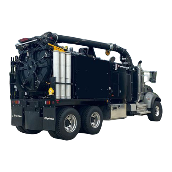
Principles of Operation Equipment Specifications The Mud Dog 700 is designed for removing soil from around utilities such as gas, water, electric and telephone lines as well as in industrial plants for exposing buried Maximum vacuum pressure rating of vacuum system lines of any nature. - Page 64 PRE-OPERATION Figure 2-1 2-Pre-Operation Section 2-2 Super Products LLC Publication: 0044321...
-
Page 65: Vacuum System
(1000) GPM through a six (6) inch hose can be 320°F. Deviations from this maximum operating realized. temperature must be approved by Super Products. Super Products LLC Publication: 0044321 2-Pre-Operation Section 2-3... -
Page 66: Airflow
7. The air goes from the outside of the filter (#6) to the This air cools the vacuum pump allowing for high inside of the filter. Any remaining material, ten vacuum. Figure 2-2 2-Pre-Operation Section 2-4 Super Products LLC Publication: 0044321... -
Page 67: Vacuum Pump Operation
Depress clutch again and select the proper forward gear. The proper gear should be the 6. When done vacuuming, open the vacuum relief door. highest forward gear which will keep the engine Reduce the engine speed to idle. Super Products LLC Publication: 0044321 2-Pre-Operation Section 2-5... -
Page 68: Vacuum Relief Valves
7. Transfer Case/Vacuum Pump Disengagement • Manual Transmission with Manual Shift or Air Shift Transfer Case. Super Products offers two (2) types of vacuum relief valves. The in-line "T" type vacuum relief valve is a) Fully depress the clutch pedal. -
Page 69: Operation Instructions - "T" Type Vacuum Relief
See section on testing of remote operated vacuum relief valve before using due to possible serious injury or death. Super Products LLC Publication: 0044321 2-Pre-Operation Section 2-7... -
Page 70: Suction Line Connections
PRE-OPERATION Suction Line Connections Suction Line Set Up Guidelines Super Products hose-to-hose and hose-to-tube connections provide for fast set up of suction lines. This 1. Install relief valve as shown in this manual. is achieved by providing loose fitting male and female 2. -
Page 71: Water System
The water system is used to loosen soils as well as for you are traveling or when stationary. general cleanup. Various nozzles are available depending on soil conditions. A drain valve allows for draining the tank (10). Figure 2-3 Super Products LLC Publication: 0044321 2-Pre-Operation Section 2-9... -
Page 73: Control System Operation
Service Hydraulic Filter indicator light - change in- tank hydraulic filter when lit. • Cabin Heater Switch - turns on dual cabin heater fans, three speed settings. • LCD Display Super Products LLC Publication: 0044321 3-Control System Operation Section 3-1... -
Page 74: Emergency Stop
Pressing the small red E-Stop button on either remote will: • Open the vent door • Halt all hydraulic functions • Bring the engine to an idle 3-Control System Operation Section 3-2 Super Products LLC Publication: 0044321... - Page 75 Knurled Collar for desired function. For D03 Valves, push spool left or right with small Allen key. • Turn out proportional control valve until pressure gauge reads less than 200 psi. Super Products LLC Publication: 0044321 3-Control System Operation Section 3-3...
-
Page 76: Boom Operation
When operating the boom, make sure you watch for and the appropriate extensions and work nozzle. overhead electrical wires or anything else which could result in serious injury, death or property damage. 3-Control System Operation Section 3-4 Super Products LLC Publication: 0044321... -
Page 77: Water Heater Operation
Never exceed the pressure rating of your system. increase button until desired pump speed is reached. Super Products supplies systems rated at 2500 and The control system obeys the most recent command 3000 PSI. Know which system you have. Repair or from either the remote control or the speed dial. -
Page 78: Winter Recirculation System
"Water Lance Operation" section. 13. Then turn on the winter recirculation switch on the control panel. Water will circulate through the entire system both when you are traveling and when stationary. 3-Control System Operation Section 3-6 Super Products LLC Publication: 0044321... -
Page 79: Air Purge
Never depend only on blowing the water out of your system (if you have an optional water heater) as not all the water will drain from the heater and could freeze causing heater coil damage Super Products LLC Publication: 0044321 3-Control System Operation Section 3-7... -
Page 80: Anti Freeze System
6. Replace the inlet strainer screen and cup. 7. Open the antifreeze supply valve. 8. Close the water tank return valve. 9. Close the manifold drain valve & bypass valve 3-Control System Operation Section 3-8 Super Products LLC Publication: 0044321... -
Page 81: Lance/Cleaning Gun Precautions
Operate the gun if there are any leaks from the Never exceed maximum operating pressure. Make sure packing, fittings, hoses, etc. relief valve is properly operating. Tap or otherwise lock trigger into the ON position. Super Products LLC Publication: 0044321 3-Control System Operation Section 3-9... -
Page 82: Dumping Payload
Figure 3-11 elsewhere in this manual. NOTE 3. From main control panel set "Dig-Dump" mode The boom should be positioned in its cradle when raising switch to "DUMP". the body. 3-Control System Operation Section 3-10 Super Products LLC Publication: 0044321... -
Page 83: Separator Air System
Equipment damage will occur if the body is raised too high or the container is too tall. Super Products LLC Publication: 0044321 3-Control System Operation Section 3-11... -
Page 85: Lubrication And Maintenance
Each maintenance item is numbered and is described on Synthetic Machine Oil the pages following the schedule. ISO 150 Anti-Freeze Super Products Spec 20 Gallons 3060-00036 100 Plus RV Anti- Freeze Super Products LLC Publication: 0044321 4-Lubrication and Maintenenace Section 4-1... - Page 86 Boom Pendant Plug Inspect Clean/Lubricate and Receptacle (optional) HYDRAULIC SYSTEM Hydraulic Oil Inspect Replace Hydraulic Oil For extended hydraulic oil life perform an oil sample analysis and consultation with a lubrication expert 4-Lubrication and Maintenenace Section 4-2 Super Products LLC Publication: 0044321...
- Page 87 See Pump Section WATER RECIRCULATION Check Valve Inspect AIR PURGE Ball Valve Inspect Check Valve Inspect CABINET AND TOOL BOX DOORS Hinges Lubricate Latches Lubricate/Adjust Foam Gasket Inspect PTO GREASE Lubricate Super Products LLC Publication: 0044321 4-Lubrication and Maintenenace Section 4-3...
-
Page 88: Maintenance Items
Add oil if necessary. Initially change oil in water pump after 100 hours of operation and then every twelve (12) months or 1,000 hours whichever comes first. Refer to 'Recommended Lubricants' in this manual. 4-Lubrication and Maintenenace Section 4-4 Super Products LLC Publication: 0044321... -
Page 89: Water System
3. Water Tank Connections: Inspect water tank the top of the debris body. Call Super Products at 1-800- connections for leaks, damage, or wear monthly. 837-9711 for assistance in diagnosing and correcting. - Page 90 Retighten roller bolts securely and recheck wedge adjustment, as above. Recheck leakage and repeat roller adjustment as necessary. Figure 4-1 Flat Tailgate 4-Lubrication and Maintenenace Section 4-6 Super Products LLC Publication: 0044321...
-
Page 91: Troubleshooting
This guide is intended as a quick reference to aid human error. operators and technicians in troubleshooting potential 7. Verify the symptom is gone. Super Products’ Mud Dog® Vacuum issues with the Excavator This guide describes symptoms and lists several probable causes and their solutions. - Page 92 Lack of air pressure Check chassis air pressure. Run engine until pressure rises. Electric signal not present. Check electric troubleshooting. Transfer Case Failed speed sensor on transfer Replace speed sensor. 5-Troubleshooting Section 5-2 Super Products LLC Publication: 0044321...
- Page 93 Inspect suction hose and fittings from hydraulic oil tank to pump for air leak. Water in oil Drain all oil in system, replace oil and oil filter. Inspect or replace hydraulic reservoir fill cap. Super Products LLC Publication: 0044321 5-Troubleshooting Section 5-3...
- Page 94 See - Electrical troubleshooting. Boom functions are noisy. Dry bearing or pivot points. Lubricate bearing and pivot points. No Water Pressure Water supply valve closed. Open supply valve. Water tanks empty. Fill water tanks. 5-Troubleshooting Section 5-4 Super Products LLC Publication: 0044321...
- Page 95 Plugged or dirty fuel filter at water Replace fuel filter. heater. Water flow switch not sensing. See - Electrical Troubleshooting. Electric signal not present. See - Electrical Troubleshooting. Super Products LLC Publication: 0044321 5-Troubleshooting Section 5-5...
- Page 96 Proximity sensor too far from Screw in proximity sensor until it component to be sensed. repeatable senses the component. Truck engine dies. Red E-STOP kill button depressed. Twist & pull out red E-STOP button. 5-Troubleshooting Section 5-6 Super Products LLC Publication: 0044321...
-
Page 97: Electrical Troubleshooting
Check REAR AXLE DISEN LT output LED is lit on the control module. Test prox switch with metal to get prox LED to light. Display not showing. Speed sensor failure. Replace. Super Products LLC Publication: 0044321 5-Troubleshooting Section 5-7... - Page 98 Not switching between dig Dig/Dump signal not Check if DUMP MODE SW and dump mode. present. input LED is lit on the control module. Other electrical problem. See - Common Electrical Problems. 5-Troubleshooting Section 5-8 Super Products LLC Publication: 0044321...
- Page 99 See - Remote Throttle Control. enabled. Wireless pendant not See - Pendant Control. working. Variable water flow See - Common Electrical potentiometer failure. Problems. Proportional valve failed. Perform manual override to verify electrical issue. Super Products LLC Publication: 0044321 5-Troubleshooting Section 5-9...
- Page 100 Check circuit breaker status. breaker is blown. Burner control system is in Water heater master control lock-out mode. switch off, then back on. Observe burner operation sequence. See - Water Heater burner control. 5-Troubleshooting Section 5-10 Super Products LLC Publication: 0044321...
- Page 101 Water heat burner not See - Water Heater and Burner running. Control Lights Lights will not work. Too much current load. See - Common Electrical Problems Circuit breaker tripped. See - Common Electrical Problems Super Products LLC Publication: 0044321 5-Troubleshooting Section 5-11...
- Page 102 Remote Throttle not See - Remote Throttle Control functioning. enabled. Connector not completely Check that pendant bridge plugged in. CAN 2 LED is lit red. Cord is damaged. See - Common Electrical Problems. 5-Troubleshooting Section 5-12 Super Products LLC Publication: 0044321...
- Page 103 Output on but function not Ground return wire failure. See- Loss of electrical working. connection. Device has failed to See - Device failed. operate. Loss of electrical Cut, broken or dislodged Repair wiring. connection. wire. Super Products LLC Publication: 0044321 5-Troubleshooting Section 5-13...
-
Page 104: Winter Recirculation Troubleshooting
5. Turn the high pressure water bypass valve closed 6. Turn the Water Heater switch on at the control panel. The Water Heater SW LED is lit. 5-Troubleshooting Section 5-14 Super Products LLC Publication: 0044321... -
Page 105: Hydraulic System
TROUBLESHOOTING Hydraulic System Super Products LLC Publication: 0044321 5-Troubleshooting Section 5-15... -
Page 106: Electric Block Diagram
TROUBLESHOOTING Electric Block Diagram 5-Troubleshooting Section 5-16 Super Products LLC Publication: 0044321... - Page 107 TROUBLESHOOTING Control System Schematic Super Products LLC Publication: 0044321 5-Troubleshooting Section 5-17...
- Page 108 TROUBLESHOOTING Control System Schematic 5-Troubleshooting Section 5-18 Super Products LLC Publication: 0044321...
- Page 109 TROUBLESHOOTING Control System Schematic Super Products LLC Publication: 0044321 5-Troubleshooting Section 5-19...
- Page 110 TROUBLESHOOTING Control System Schematic 5-Troubleshooting Section 5-20 Super Products LLC Publication: 0044321...
- Page 111 TROUBLESHOOTING Control System Schematic Super Products LLC Publication: 0044321 5-Troubleshooting Section 5-21...
- Page 112 TROUBLESHOOTING Control System Schematic 5-Troubleshooting Section 5-22 Super Products LLC Publication: 0044321...
- Page 113 TROUBLESHOOTING Control System Schematic Super Products LLC Publication: 0044321 5-Troubleshooting Section 5-23...
- Page 114 TROUBLESHOOTING Control System Schematic 5-Troubleshooting Section 5-24 Super Products LLC Publication: 0044321...
- Page 115 TROUBLESHOOTING Control System Schematic Super Products LLC Publication: 0044321 5-Troubleshooting Section 5-25...
- Page 116 TROUBLESHOOTING Control System Schematic 5-Troubleshooting Section 5-26 Super Products LLC Publication: 0044321...
- Page 117 TROUBLESHOOTING Control System Schematic Super Products LLC Publication: 0044321 5-Troubleshooting Section 5-27...
- Page 118 TROUBLESHOOTING Control System Schematic 5-Troubleshooting Section 5-28 Super Products LLC Publication: 0044321...
- Page 119 TROUBLESHOOTING Control System Schematic Super Products LLC Publication: 0044321 5-Troubleshooting Section 5-29...
- Page 120 TROUBLESHOOTING Control System Schematic 5-Troubleshooting Section 5-30 Super Products LLC Publication: 0044321...
- Page 121 TROUBLESHOOTING Control System Schematic Super Products LLC Publication: 0044321 5-Troubleshooting Section 5-31...
- Page 122 TROUBLESHOOTING Control System Schematic 5-Troubleshooting Section 5-32 Super Products LLC Publication: 0044321...
- Page 123 TROUBLESHOOTING Control System Schematic Super Products LLC Publication: 0044321 5-Troubleshooting Section 5-33...
- Page 124 TROUBLESHOOTING Control System Schematic 5-Troubleshooting Section 5-34 Super Products LLC Publication: 0044321...
- Page 125 TROUBLESHOOTING Control System Schematic Super Products LLC Publication: 0044321 5-Troubleshooting Section 5-35...
- Page 126 TROUBLESHOOTING Control System Schematic 5-Troubleshooting Section 5-36 Super Products LLC Publication: 0044321...
-
Page 127: Service And Spare Parts
2.0 Yellow Pills for Quad Nozzle #6 0042129 6” Male Dig Tube 0034854 Intermediate Hose 8” - 110” 0034847-05110 Boom End Hose 8” - 128” 0034847-05128 Tailgate Lock Rod 0034066 Super Products LLC Publication: 0044321 6-Service and Spare Parts Section 6-1... - Page 128 Water Heater Control Module 5500-013189 Water Heater Ignitor 7310-02761 Water Heater Electrode Kit 7310-02941 Water Heater CAD Cell 7310-03070 Water Heater Flow Switch 0043343 KT22A Water Pump Rebuild Kit 0041014 6-Service and Spare Parts Section 6-2 Super Products LLC Publication: 0044321...
-
Page 129: Index
1-15 Determine Maximum Turning Speed Before Operating on Job Site Safety and Hazard Warnings 1-14 Roads or Uneven Ground 1-13 Determine Stopping Characteristics of Truck for Trans- porting Braking Tests 1-13 Dumping Payload 3-10 Super Products LLC Publication: 0044321 Index-1... - Page 130 1-16 1-17 1-18 Preventive Maintenance Instructions 4-1 Vacuum Operation 1-18 Principles of Operation 2-1 Vacuum Operation Safety 1-17 Pure Vacuum 2-3 Vacuum Pump Operation 2-5 Vacuum Refief Valves 2-6 Vacuum Relief Valve Safety 1-19 Index-2 Super Products LLC Publication: 0044321...
- Page 131 Water Heater Operation 3-5 Water Lance Operation 3-4 Water System 2-6 When Transporting Equipment 1-13 When Using Pressurized Air or Water 1-4 Winter Recirculation System 3-6 Winter Recirculation Troubleshooting 5-14 Working with Tools and Equipment 1-10 Super Products LLC Publication: 0044321 Index-3...
- Page 134 Contact Super Products if you require additional information regarding the operation of your Mud Dog Vacuum Excavator. 130 W BOXHORN DR. MUKWONAGO, WI 53149 • P: 800.837.9711 • www.superproducts.com Super Products LLC Publication: 0044321 ©2023 Super Products LLC 1/2023...
Need help?
Do you have a question about the MUD DOG 700 and is the answer not in the manual?
Questions and answers