Table of Contents
Advertisement
Quick Links
Advertisement
Table of Contents

Related Manuals for AmpliVox Otowave 202-H


Summary of Contents for AmpliVox Otowave 202-H
- Page 1 Otowave 202 & 202-H Operating Manual...
- Page 2 READ THIS OPERATING MANUAL BEFORE ATTEMPTING TO USE THE INSTRUMENT. This manual is valid for the Otowave 202 & 202-H (applies from firmware version 1.0.0.072200 onwards – see System Information screen). This product is manufactured by: Amplivox Ltd. 3800 Parkside, Solihull Parkway, Birmingham Business Park, Birmingham, West Midlands,...
- Page 4 For supply in US only Caution: Federal Law restricts this device to sale by or on the order of a licenced medical professional.
-
Page 5: Table Of Contents
TABLE OF CONTENTS INTRODUCTION ................................1 1.1. THANK YOU ................................... 1 1.2. INTENDED APPLICATIONS .............................. 1 1.3. FEATURES ..................................1 1.4. UNPACKING ................................... 1 1.5. STANDARD CONTENTS AND OPTIONAL ACCESSORIES ....................2 1.6. WARNINGS ..................................2 1.7. GUARANTEE................................... 2 IMPORTANT SAFETY INSTRUCTIONS ........................... 3 2.1. - Page 6 DATA TRANSFER TO NOAH OR AMPLISUITE ......................27 DATA MANAGEMENT ..............................28 10.1. LIST RECORDS ................................28 10.2. DELETE RECORDS ................................. 29 10.3. PRINT RECORDS ................................29 10.4. CONNECT VIA USB ............................... 29 PERFORMING DAILY CHECKS ............................. 30 SYSTEM INFORMATION ............................. 31 ROUTINE MAINTENANCE ............................
-
Page 7: Introduction
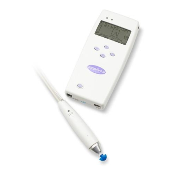
INTRODUCTION 1. INTRODUCTION 1.1. THANK YOU Thank you for purchasing the Amplivox Otowave 202, a portable tympanometer incorporating an ergonomically-designed remote probe assembly that will give many years of reliable service if treated with care. This operating manual applies to the Otowave 202 which is available as a standard option (with 226Hz probe tone) and as an H-option (with 226Hz and 1000Hz probe tones). -
Page 8: Standard Contents And Optional Accessories
Amplivox service department. Return carriage is free of charge for customers in the UK and chargeable for overseas customers. -
Page 9: Important Safety Instructions
IMPORTANT SAFETY INSTRUCTIONS 2. IMPORTANT SAFETY INSTRUCTIONS The Otowave 202 instrument must be used only by practitioners qualified to perform tympanometric tests. It is intended for transient use as a screening and diagnostic tool; however no surgical or medical procedure should be undertaken solely on the basis of results obtained from the instrument. -
Page 10: Power Supply Options
The relevant part numbers are indicated in Section 16. For connected parts marked * only connect the accessories supplied with the instrument or supplied by Amplivox or an Amplivox distributor. These parts have been tested for use with the Otowave 202 tympanometer D-0115692-I (OM031) –... -
Page 11: Data Transfer To A Printer
The tympanometer is supplied with software to allow connection to a computer for the transfer of test results (see Section 8). You must use the designated USB cable which is available from Amplivox (see Section 15). D-0115692-I (OM031) –... -
Page 12: Principles Of Operation
PRINCIPLES OF OPERATION 3. PRINCIPLES OF OPERATION 3.1. OTOSCOPIC EXAMINATION A suitably-qualified health care professional should perform a thorough otoscopic examination to establish that the condition of the ear is suitable for the test options selected and that no contraindications are present. The latter would include obstruction of the external ear canal due to excessive wax and/or hairs, both of which would need to be removed. -
Page 13: Acoustic Reflex Measurement
PRINCIPLES OF OPERATION 3.4. ACOUSTIC REFLEX MEASUREMENT Using the same principle as in tympanometry measures, it is also possible to establish whether an acoustical reflex is present. The acoustic reflex is caused by the contraction of the stapedial muscle as a response to high-intensity stimulation of the ear. -
Page 14: Using The Otowave
USING THE OTOWAVE 4. USING THE OTOWAVE This instrument is equipped with a real-time clock. Before use, please set the date & time to local values in order to ensure that test data and calibration status are correctly identified. Refer to Section 6. 4.1. -
Page 15: Controls And Indicators (Base Unit)
USING THE OTOWAVE 4.3. CONTROLS AND INDICATORS (BASE UNIT) Press the On/Off key momentarily to turn the Otowave 202 on (refer to the diagram below). No warm-up time is required, although a short diagnostic routine will run for a few seconds. During this time the internal pump will operate. -
Page 16: The Probe
USING THE OTOWAVE 4.5. THE PROBE 4.5.1. CONTROLS AND INDICATORS (PROBE) Indicator light Indicates if testing is in process or not. Function button Quick view of the test settings currently used or change of baselinemode. Probe tip with ear tip 4.5.2. -
Page 17: Contralateral Transducer
USING THE OTOWAVE 4.6. CONTRALATERAL TRANSDUCER Ear tip Ear tip to be placed on probe tip of contra phone Probe tip Probe tip screwed onto contra phone Plug Connector to CONTRA socket on Otowave The contralateral transducer is used when it is required to provide a reflex stimulus to the opposite ear to that being tested with the main probe assembly. -
Page 18: Taking Measurements
TAKING MEASUREMENTS 5. TAKING MEASUREMENTS Ensure that the appropriate settings have been made before carrying out a test. See below and the CONFIGURATION options in Section 6, To view the test settings ensure that the MAIN MENU is displayed and then press and hold the function button on the probe to display the TEST SETTINGS screen as shown below. -
Page 19: Performing A Test
TAKING MEASUREMENTS Ensure that the ear tip is pushed all the way down on the probe tip and that there is no gab between probe tip and ear tip. The small holes through the Otowave probe tip must be kept clear. - Page 20 TAKING MEASUREMENTS TESTING LEFT EAR Pressure Settling Cancel Press ◄ at any time to cancel the test and return to the ear selection menu. TESTING LEFT EAR ✓ Seal Obtained Taking Tympanogram Cancel Once an adequate seal is detected the tympanogram measurement is made. This takes about 3 seconds. It is important not to move the probe and to ask the patient to remain very still during the test.
- Page 21 TAKING MEASUREMENTS Remove the eartip from the patient and after a short period the tympanogram will be displayed. The form of the tympanogram will depend on the baseline mode selected and the following illustration is for a 226Hz probe with the default offset of +200daPa. See Section 5.5 for a description of the displays for other baseline modes. Pk : 1.2ml/-46daPa ...
- Page 22 TAKING MEASUREMENTS If the reflex test was performed at more than one frequency use the ▲ and ▼ keys to view the results for the other frequencies. If the Otowave 202 was set to test for a reflex at all levels of the stimulus (see Reflex autostop in Section 5.7) press ►...
- Page 23 TAKING MEASUREMENTS Please note: Results of the last test will be erased as soon as a new test is started. Test results should be saved to the Otowave’s database, printed or sent to a computer to ensure that data is not lost. D-0115692-I (OM031) –...
-
Page 24: Configurations
CONFIGURATIONS 6. CONFIGURATIONS 6.1. SWEEP SETTINGS Video available on when to change tympanometry settings. ITEM DESCRIPTION DEFAULT Sweep Speed: The rate of change of air pressure may be selected to be 100daPa/s 200 daPa/s 200daPa/s or 300daPa/s. This determines the time taken for a pressure sweep from +200 to -400 daPa (6, 3 and 2 seconds, respectively). -
Page 25: Scalar And Vector Mode - 1000 Hz (202-H Option)
CONFIGURATIONS 6.1.2. SCALAR AND VECTOR MODE – 1000 HZ (202-H OPTION) Scalar Mode For 1000Hz operation a similar scalar display mode is available as used for 226Hz (Y-only compensation). The tympanogram format is shown below; however vector display mode may provide better results for some patients (e.g. -
Page 26: Selecting Alternative Display Modes
CONFIGURATIONS Component Mode This 1000Hz mode displays the separate admittance, susceptance & conductance (YBG) information contained within the tympanogram. This is suitable for all patients, and the display format is shown below. mƱ mƱ Admittance Y Susceptance B daPa daPa -400 -200 -400... -
Page 27: Reflex Options
CONFIGURATIONS However if difficulty is experienced in using the eartips to create a seal the alternative THOROUGH option may be helpful. This checks that a range of pressures will be available before starting a test by means of a visual indication of the quality of the seal: TESTING LEFT EAR “Obtaining ear seal”... - Page 28 CONFIGURATIONS frequencies at which the reflex stimulus is to be applied. Then press ► to save the entire selection. Selection: Only if peak found Use the ▲ and ▼ keys to choose the circumstances when a reflex measurement is to be made (always, never, only if a compliance peak is found, or only after confirmation is made at the start of the test sequence).
-
Page 29: System Settings
CONFIGURATIONS 6.3. SYSTEM SETTINGS ITEM DESCRIPTION DEFAULT Set the internal clock date and time. Use the ◄ and ► keys to select Time/Date: a field and the ▲ and ▼ keys to adjust the value. Printer: Select thermal printer you want to use with the unit (Sanibel MPT-II MPT-II or Able AP1300). -
Page 30: Saving Results In The Internal Database
SAVING RESULTS IN THE INTERNAL DATABASE 7. SAVING RESULTS IN THE INTERNAL DATABASE Up to 18 tests can be stored in the Otowave’s internal database. To save the results of a test select SAVE RESULTS from the PROCESS RESULTS menu that is displayed on completion of a test. -
Page 31: Sending The Results To A Printer
SENDING THE RESULTS TO A PRINTER 8. SENDING THE RESULTS TO A PRINTER Video available on how to print using the Sanibel MPT-II printer. Two thermal printers (the Able AP1300 or Sanibel MPT-II) are available as options for use with the Otowave 202 both of which communicate via an infra-red link (IrDA). - Page 32 SENDING THE RESULTS TO A PRINTER PLEASE WAIT Trying to connect.. Do Not break IR link! Cancel The Otowave 202 will then attempt to connect to the printer. When this has been done the data will be transferred. During this time the following message is displayed. PLEASE WAIT Sending Record Do Not break IR link!
-
Page 33: Data Transfer To Noah Or Amplisuite
To transfer test results stored within the tympanometer to a NOAH database the Amplivox NOAH Impedance module must be installed on to a computer. Alternatively, Amplivox ampliSuite allows data to be transferred to a computer and subsequently viewed, annotated & printed. This software is supplied on a CD which includes this operating manual. -
Page 34: Data Management
DATA MANAGEMENT 10. DATA MANAGEMENT Records stored in the database of the Otowave 202 can be listed, viewed, printed, deleted or sent to a computer using the DATA MANAGEMENT option of the main menu: DATA MANAGEMENT LIST RECORDS DELETE RECORDS PRINT RECORDS ... -
Page 35: Delete Records
DATA MANAGEMENT • View the selected record • Print the selected record (using the currently displayed baseline mode) • Delete the selected record 10.2. DELETE RECORDS DELETE RECORDS allows a group of records to be deleted. It is possible to delete all records, all records that have been printed or all records that have been sent to a computer. -
Page 36: Performing Daily Checks
PERFORMING DAILY CHECKS 11. PERFORMING DAILY CHECKS The operation of the Otowave 202 should be checked daily using the 4 in 1 test cavity assembly supplied with the instrument. Select the DAILY CHECK option in the main menu: DAILY CHECK INSERT PROBE Cancel Wait until “Open”... -
Page 37: System Information
SYSTEM INFORMATION 12. SYSTEM INFORMATION To review version related information of your instrument, access the start screen and use the down arrow key to move all the way to the bottom of the screen. Select System Information to find useful information such as variant of your instrument (102-1 or 102-4) and upcoming calibration dates. -
Page 38: Routine Maintenance
13.3. CALIBRATION AND RETURN OF THE INSTRUMENT Amplivox recommends that the Otowave is calibrated annually. A warning message will be displayed at power up if the instrument was calibrated more than twelve months ago. The date of the last calibration is displayed on the SYSTEM INFORMATION screen. - Page 39 ROUTINE MAINTENANCE The instrument should be returned to the manufacturer for service & repair. WARNING There are no user-serviceable parts within it. When packing the instrument for shipping, please use the original shipping carton and packing materials. Place the instrument parts in plastic bags before packing to prevent dirt and dust getting into the probe. Do not return the batteries with the instrument.
-
Page 40: Error Messages & Fault Conditions
ERROR MESSAGES & FAULT CONDITIONS 14. ERROR MESSAGES & FAULT CONDITIONS If a fault condition cannot be cleared, the operator is cautioned against repeatedly starting the instrument. Please note: Refer to the installation & operating instructions provided with the NOAH Impedance Module or ampliSuite software for details of the data transfer operation and errors that may occur. - Page 41 If difficulties resolving fault conditions occur the equipment distributor (or Amplivox if purchased directly) should be consulted. Error messages related to sending data to a computer Connection to a computer is made automatically when the USB cable is connected as long as the appropriate software (NOAH Interface or ampliSuite) has been installed and the Otowave 202 has the main menu displayed.
- Page 42 ERROR MESSAGES & FAULT CONDITIONS Refer to the installation & operating instructions provided with the NOAH Impedance Module or ampliSuite software for details of the data transfer operation and errors that may occur. If data transfer is not required simply unplug the USB cable and the Otowave 202 will return to normal operation. D-0115692-I (OM031) –...
-
Page 43: Technical Specification
TECHNICAL SPECIFICATION 15. TECHNICAL SPECIFICATION 15.1. PERFORMANCE Tympanometry Instrument type Meatus compensated tympanometer Analysis performed Admittance peak level (in ml or mƱ ) & pressure; Gradient in daPa (for 226Hz); Ear Canal Volume (ECV) @ 200 daPa Probe tone frequency, level 226Hz +/- 2%;... - Page 44 TECHNICAL SPECIFICATION Reflex analysis Reflex pass/fail at each level tested; maximum amplitude of each reflex; nominal pressure used for the reflex test (computer display only) Pressure used for reflex measurement Pressure at tympanogram peak (if found) or at 0daPa Reflex stimulus control Stimulus presented at all levels, or Stimulus ceases when a reflex is found Reflex detection threshold and accuracy...
-
Page 45: Equipment Classification
TECHNICAL SPECIFICATION Weight (probe, incl connection) 110g Interconnection (probe to base) 1.5m combined electrical cable and air tube Environmental Operating temperature range C to +35 Operating humidity range 30% to 90% RH (non-condensing) Operating atmospheric pressure range 980 hPa to 1040 hPa (see Section 2) Transport storage temperature... - Page 46 TECHNICAL SPECIFICATION Definition: Date of Manufacture Definition: Manufacturer D-0115692-I (OM031) – Otowave 202 Operating Manual...
-
Page 47: Ordering Consumables And Accessories
ORDERING CONSUMABLES AND ACCESSORIES 16. ORDERING CONSUMABLES AND ACCESSORIES To order consumables, additional accessories and to replace detachable parts that have been damaged, please contact Amplivox for current prices and delivery charges. The items available are listed below: DESCRIPTION STOCK NO. -
Page 48: Disposal Information
DISPOSAL INFORMATION 17. DISPOSAL INFORMATION Amplivox Limited is fully compliant with the WEEE (Waste Electrical and Electronic Equipment) Regulations. Our PRN (Producer Registration Number) is WEE/GA0116XU and we are registered with the approved WEEE Compliance Scheme, B2B Compliance, approval number WEE/MP3338PT/SCH. -
Page 49: Emc Guidance & Manufacturer's Declaration
EMC GUIDANCE & MANUFACTURER’S DECLARATION 18. EMC GUIDANCE & MANUFACTURER’S DECLARATION Guidance and manufacturer’s declaration – electromagnetic emissions The Otowave 202 Tympanometer is intended for use in the electromagnetic environment specified below. The customer or user of the Otowave 202 Tympanometer should assure that it is used in such an environment. - Page 50 EMC GUIDANCE & MANUFACTURER’S DECLARATION Immunity test IEC 60601 test level Compliance level Electromagnetic environment – guidance Voltage dips, short <5% U <5% U Mains power quality should be interruptions and voltage (>95% dip in U ) for (>95% dip in U ) for that of a typical commercial or variations...
- Page 51 EMC GUIDANCE & MANUFACTURER’S DECLARATION Guidance and manufacturer’s declaration – electromagnetic immunity (2) The Otowave 202 Tympanometer is intended for use in the electromagnetic environment specified below. The customer or user of the Otowave 202 Tympanometer should assure that it is used in such an environment.
- Page 52 EMC GUIDANCE & MANUFACTURER’S DECLARATION Guidance and manufacturer’s declaration – electromagnetic immunity (2) Field strengths from fixed transmitters, such as base stations for radio (cellular/cordless) telephones and land mobile radios, amateur radio, AM and FM radio broadcast and TV broadcast cannot be predicted theoretically with accuracy.
-
Page 53: Use With Non-Medical Electrical Equipment
Refer to Diagrams 1 to 3 below for typical configurations of connected peripheral equipment. Refer to Amplivox Limited at the address given on the front of this user manual if advice is required regarding the use of peripheral equipment. - Page 54 USE WITH NON-MEDICAL ELECTRICAL EQUIPMENT Diagram 1: Otowave 202 used with the medically-approved mains adapter Mains Outlet Medical Mains Adapter Otowave 202 Tympanometer D-0115692-I (OM031) – Otowave 202 Operating Manual...
- Page 55 USE WITH NON-MEDICAL ELECTRICAL EQUIPMENT Diagram 2: Otowave 202 used with the supplied printer Mains Outlet Printer via IrDA Link Printer Power Supply Otowave 202 Tympanometer D-0115692-I (OM031) – Otowave 202 Operating Manual...
- Page 56 Diagram 3: Otowave 202 used with the medically-approved mains adapter and a computer Mains Outlet Medical Mains Adapter Otowave 202 Tympanometer Mains Outlet Computer Power Supply Computer via USB socket D-0115692-I (OM031) – Otowave 202 Operating Manual...
-
Page 57: 1000Hz Tympanometry And Meatus Compensation
1000HZ TYMPANOMETRY AND MEATUS COMPENSATION 20. 1000HZ TYMPANOMETRY MEATUS COMPENSATION 20.1. TYMPANOMETRIC PROPERTIES Tympanometric measurements of the ear are affected by a large number of physiological characteristics, but from a tympanometer's perspective these can be reduced to the three physical properties: •... -
Page 58: Additional Points To Consider
Y display alone gives misleading or ambiguous conclusions. All these display modes are available via Amplivox “ampliSuite”, an application which allows tympanometric test results to be downloaded and displayed on a computer. - Page 59 1000HZ TYMPANOMETRY AND MEATUS COMPENSATION Figure 1: 226 Hz probe tone: The distance between the n sample Y (admittance value of the n sample in the tympanogram) and the baseline sample Y is essentially the same as the difference in lengths between the length |��_����...
- Page 60 Copyright © 2020 Amplivox Ltd. All rights reserved. No part of this publication may be reproduced or transmitted in any form or by any means without the prior written permission of Amplivox Ltd. D-0115692-I (OM031) – Otowave 202 Operating Manual...
Need help?
Do you have a question about the Otowave 202-H and is the answer not in the manual?
Questions and answers