Table of Contents
Advertisement
Quick Links
Advertisement
Table of Contents

Subscribe to Our Youtube Channel
Related Manuals for AmpliVox 270+


Summary of Contents for AmpliVox 270+
- Page 1 270+ Operating Manual...
- Page 2 ABOUT THIS MANUAL READ THIS OPERATING MANUAL BEFORE ATTEMPTING TO USE THE INSTRUMENT. This manual is valid for the 270+ (from firmware version 1.3.1.0 onwards). This product is manufactured by: Amplivox Ltd 3800 Parkside, Solihull Parkway, Birmingham Business Park, Birmingham, West Midlands, B37 7YG www.amplivox.com...
-
Page 3: Table Of Contents
TABLE OF CONTENTS INTRODUCTION 1.1. HANK YOU 1.2. NTENDED APPLICATIONS 1.3. ONTRAINDICATIONS 1.4. TANDARD AND OPTIONAL ACCESSORIES 1.5. ARNINGS UNPACKING AND INSTALLATION 2.1. ENERAL 2.2. ARKINGS 2.3. AFETY INSTRUCTIONS 2.3.1. General 2.3.2. Cautions – General 2.3.3. Environmental factors 2.3.4. Electrical and electrostatic safety 2.3.5. - Page 4 4.6.6. Signal 4.6.6.1. Selection of Tone and speech module 4.6.6.2. Continuous, present and Pulse 4.6.7. Ear (Selection) 4.6.8. mask (activate masking) 4.6.9. output (Ac, BC and freefield) 4.6.10. AUTO (automATIC testing) 4.6.11. >100dB (extended range) 4.6.12. special (Special test selection) 4.7.
- Page 5 5.3.3. Insert Masker 5.3.4. Insert Earphones 5.3.5. Mains adapter maintenance 5.4. CCESSORIES REPLACEMENT PARTS 5.5. EPAIR 5.6. ARRANTY 5.7. ALIBRATION AND ETURN OF THE NSTRUMENT TECHNICAL SPECIFICATIONS 6.1. TANDARD AND REGULATORY 6.2. ENERAL 6.3. UDIOMETRY 6.4. PEECH TESTING 6.5. AXIMUM HEARING LEVELS PROVIDED BY EACH FREQUENCY 6.6.
-
Page 6: Introduction
1. INTRODUCTION 1.1. THANK YOU Thank you for purchasing an Amplivox 270+, a desktop-controlled audiometer that will give many years of reliable service if treated with care. 1.2. INTENDED APPLICATIONS This instrument is designed for use by trained personnel only, such as audiologists, ENT surgeons, doctors,... -
Page 7: Standard And Optional Accessories
1.4. STANDARD AND OPTIONAL ACCESSORIES Shipping documentation will reference the stock number quoted below, and images of the parts alongside the relevant stock number are available on the Amplivox website (www.amplivox.com). The required fitting instructions are supplied with each part. -
Page 8: Unpacking And Installation
Failing to do so may endanger the environment. The CE-mark indicates that Amplivox Ltd meets the requirements of Annex II of the Medical Device Directive 93/42/EEC. TÜV Product Service, Identification No. 0123, has approved the quality system. -
Page 9: Safety Instructions
Amplivox Ltd is aware that safety rules within individual organisations vary. If a conflict exists between the instructions in this manual and the rules of the organisation using this instrument, the more stringent rules should take precedence. -
Page 10: Cautions - General
Amplivox Ltd. Equipment is not user repairable. Repairs must be performed by an authorised service representative only. No modifications of the equipment are allowed by anyone other than a qualified Amplivox Ltd representative. Modification of the equipment could be hazardous. -
Page 11: Environmental Factors
The requirement for the Separation Device is defined in IEC 60601-1 clause 16. Do not use any additional multiple socket-outlet or extension cord. Use only the Amplivox Mains Power Adaptor. 2.3.5. ELECTROMAGNETIC COMPATIBILITY (EMC) -
Page 12: Explosion Hazards
2.3.6. EXPLOSION HAZARDS Risk of explosion. WARNING Do NOT use in the presence of flammable anesthetics or other gases. Do NOT use in the presence of flammable gaseous mixtures. Users should consider the possibility of explosions or fire when using this device in close proximity to flammable anesthetic gases. -
Page 13: Mains Supply Operation
The audiometer is designed for continuous operation and is powered by a mains adapter which is supplied and specified as part of the equipment. If a replacement is required, please contact your Amplivox distributor. All other connections must be made before connecting the output lead from the adapter into the POWER input socket on the back of the audiometer. -
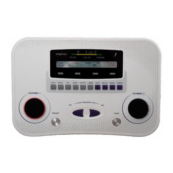
Page 14: Controls And Indicators (Base Unit)
USB connector Computer (via USB port) Please note: Only connect the accessories supplied with the instrument or supplied by Amplivox or an Amplivox distributor. These parts have been tested for use with the Amplivox 270+ audiometer for compliance with the standards IEC 60601-1 and IEC 60601-1-2. The use of accessories other than those specified may compromise compliance with these standards. -
Page 15: Light Indicators
Clear Clears all displayed test results Signal Switch between tone and speech testing Change ear Mask Activate masking Output Select transducer to present signal > 100 dB Test above 100 dB Auto Start auto test Special Select special test Menu Change instrument settings, save and reload tests Power Switch device on or off... -
Page 16: The Sanibel Mpt
2.8. THE SANIBEL MPT-II PRINTER 2.8.1. INSTALLING THE SANIBEL MPT-II PRINTER The Sanibel MPT-II thermal printer is available as an option for use with the 270+ and is connected using the cable supplied. The printer may be specified when ordering and only this printer should be used. It will be correctly configured for use. -
Page 17: Principles Of Operation
3. PRINCIPLES OF OPERATION 3.1. OTOSCOPIC EXAMINATION A suitably-qualified health care professional should perform a thorough otoscopic examination to establish that the condition of the ear is suitable for the test options selected and that no contraindications are present. The latter would include obstruction of the external ear canal due to excessive wax and/or hairs, both of which would need to be removed. -
Page 18: Using The 270
4. USING THE 270+ 4.1. GENERAL PRECAUTIONS When operating the instrument, please observe the following general precautions: CAUTION 1. Use this device only as described in this manual. 2. Be sure to use only stimulation intensities acceptable to the patient. 3. -
Page 19: Operating Language
4.4. OPERATING LANGUAGE The instrument will be set in English by default. To select the operating language for the audiometer (English or German) continue to hold the power button when switching on. An additional display will allow the selection of English (F1) or Deutsch (F2). After selecting a language, the start-up screen will show. -
Page 20: Function Buttons
4.6. FUNCTION BUTTONS 4.6.1. PRESENTING A TONE The presentation button is located to the right of the Channel 1 rotary control. The button is conductive, by touching it the test signal will be presented to the patient (presentation mode) or interrupted (continuous mode). -
Page 21: Menu Operation
4.6.4. MENU OPERATION When the start-up sequence is complete, the TONE AUDIOMETRY screen is displayed. The instrument can be operated using the four softkeys below the display as well as the 10 functional button keys below. 4.6.5. CLEAR (ON-SCREEN RESULTS) Test results from the current or a previous session can be displayed on-screen and are shown below the current test level and frequency. -
Page 22: Signal
4.6.6. SIGNAL 4.6.6.1. SELECTION OF TONE AND SPEECH MODULE Select SIGNAL to change between TONE and SPEECH audiometry. For TONE audiometry the option is given to use sinusoid or warble stimuli. Select F1 for SINE to present a sinusoid signal. Pressing F2 will present a WARBLE signal in the tone audiometry test. For SPEECH select LINE for using external speech files, such as from a CD player. -
Page 23: Mask (Activate Masking)
4.6.8. MASK (ACTIVATE MASKING) Select the MASK button to activate or deactivate masking. Select NONE (F1) to switch masking off. As soon as the masking channel is switched on, the light ring around the Channel 2 rotary control illuminates white. Use MASK (F2) to switch masking noise on and control the level manually. -
Page 24: Special (Special Test Selection)
On the display ‘+’ will indicate that levels greater than 100dBHL can be used. 4.6.12. SPECIAL (SPECIAL TEST SELECTION) Selecting the SPECIAL key enables the selection of the following special tests: • Stenger Test • Alternate Binaural Loudness Balance (ABLB) •... -
Page 25: Menu
4.7. MENU 4.7.1. GENERAL The MENU contains the system settings as well as the data processing options. • The CONFIGURATION (F1) submenu contains general instrument and test settings regarding the audiometric tests. • AUTO contains all settings related to auto-test (F2) •... -
Page 26: Auto-Test Settings
External Talkover: Select NO to use the internal microphone and YES to use an external headset with microphone. 4.7.2.1. AUTO-TEST SETTINGS ITEM DESCRIPTION DEFAULT Retry count: Select the number of times a frequency is repeated (0, 1, 2 or 3 times) if an error in testing occurs (for example, if there is an erratic response from the patient). -
Page 27: Print
To LOAD the stored set of audiogram thresholds, select the location slot (1-10) under which the data is stored (F1) and press F2 (SAVE). Select CANCEL (F4) or the MENU button again to leave the menu without changes. 4.7.4. PRINT The Sanibel MPT-II is the designated thermal printer to be used with the 270+. -
Page 28: Performing Pure Tone Audiometry
4.8. PERFORMING PURE TONE AUDIOMETRY 4.8.1. PURE TONE SCREEN The instrument will always start from the tone audiometry screen. The following information is provided on the screen: Sine or Warble Test Stimuli and Tone present Pulsed, Continuous Test Level Current present level of selected ear (in this example right ear) Test Frequency Current test frequency Masking... -
Page 29: Performing Pure Tone Audiometry
4.8.3. PERFORMING PURE TONE AUDIOMETRY Use the SIGNAL button to choose either AC or BC testing. ◄ ► Use the Channel 1 rotary control to control the level of the test stimulus. Use the left and right key change the frequency. Use the >... -
Page 30: Masking Intelligence
4.8.4.2. MASKING INTELLIGENCE When performing audiometry (with or without masking), the instrument will automatically help by informing the user that masking might be required and advise suggestions. These suggestions are based on the transducers used and will also be shown in the temporary storage of the test. SYMBOL INTERPRETATION Masking is active and efficient, no additional information is shown on screen. -
Page 31: Automatic Testing (Pure Tone Audiometry)
4.8.5. AUTOMATIC TESTING (PURE TONE AUDIOMETRY) Automatic masking can be activated by pressing the SIGNAL button. The option is given to test only one frequency on the current selected ear, all frequencies on the current selected ear or to run a full audiogram on both ears. -
Page 32: Freefield Presenting (Tone Testing)
Afterwards, select AUTO to start the automatic test sequence and the device will apply masking when needed. On screen, the wording eMASK will be shown to indicate that auto-masking is taking place. 4.8.7. FREEFIELD PRESENTING (TONE TESTING) It is possible to present the air conduction test signals (sinusoid, warble, pulsed test signal) via a loudspeaker. Select the OUTPUT button to find your FFIELD option and confirm the output by pressing softkey F3. -
Page 33: Performing Speech Audiometry
4.9. PERFORMING SPEECH AUDIOMETRY 4.9.1. GENERAL The Model 270+ has audio line in/out connections (LINE) for CD, tape player or MP3 input (e.g. for recorded speech testing) and amplifier output (MIC.). Press the FROM button to select between LINE and MIC. Output. Module Speech module SRT Test... -
Page 34: Using Live Speech (Emic.)
4.9.4. USING LIVE SPEECH (EMIC.) Users should be aware that there is a growing body of professional opinion that Live Voice speech audiometry is generally not recommended. Select eMic. to present speech via live speech. The sound will then be presented through the microphone of your external headset. -
Page 35: Masking (Speech Testing)
To use the counter the operator selects the frequency buttons: left for YES or right for NO according to the response made by the patient. The score will be automatically calculated and shown on screen. Pressing F3 (CLEAR) clears the counter to zero. To exit from the counter mode screen press F1 again. The results obtained will be saved in the temporary memory to be printed or sent to the computer. -
Page 36: Performing Special Tests
Please note: When two loudspeakers are connected to the device, use LEFT and RIGHT to select the required loudspeaker. Change the test level and frequency as usual. In order to present a test signal to one loudspeaker and a noise signal to the other, select the MASK button and control the loudness with the Channel 2 rotary control. -
Page 37: Performing Sisi
When ABLB was selected in the SPECIAL menu, ABLB will be shown in the ear selected. To start the sequence, adjust the test tone in the poorer ear to be presented at 20dB above the indicated threshold. The intensity is fixed in the impaired ear and will not be changed. The level of the better hearing ear is set 5dB above hearing threshold. -
Page 38: Performing Mha
detected increments accordingly. To delete the displayed score, select F3 (CLEAR). To return to the initial SISI display, select F4. The score is expressed as a percentage of ratio of the increments heard to the delivered increments (all increments heard = 100% and no increments heard = 0%). RESULT SISI TEST CONCLUSION RECRUITMENT 70 –... -
Page 39: Performing Hls
4.10.5. PERFORMING HLS When selecting HLS, you will be taken to the Speech Module to start the hearing loss simulation. Select F3 to change the filter settings and to present different hearing losses to the subject. Use softkey F2 to change the input from LINE to eMic. -
Page 40: Transfering Data To Pc
To transfer test results stored within the audiometer Amplivox ampliSuite allows data to be transferred to to a NOAH database the Amplivox NOAH Audilink or a computer and subsequently viewed, annotated & NOAH ampliSuite software must be installed on to a printed. -
Page 41: Routine Maintenance
Amplivox ER75. 4. If the surface of the instrument or parts of it are contaminated, it can be cleaned using a soft cloth moistened with a mild solution of water and detergent or similar. -
Page 42: Cleaning The 270
TRANSDUCER MAINTENANCE Before use check the transducer cables and connectors for signs of wear and/or damage. If you find any, please replace the item immediately by contacting Amplivox or your Amplivox distributor, requesting the relevant part number. Handle the audiometric headset, bone vibrator headset and other accessories with care. For parts that are in direct contact with the patient it is recommended that replacement parts are used or the parts are subjected to a standard disinfecting procedure between patients. -
Page 43: Mains Adapter Maintenance
Some reusable accessories are subject to wear with use over time. We recommend that you keep stock of these replacement parts. 5.5. REPAIR Amplivox Ltd is only considered to be responsible for the validity of the CE marking, effects on safety, reliability and performance of the equipment if: •... -
Page 44: Calibration And Return Of The Instrument
This shall apply solely to the original purchaser. This warranty shall not apply to any subsequent owner or holder of the product. Furthermore, this warranty shall not apply to, and Amplivox Ltd shall not be responsible for, any loss arising in connection with the purchase or use of any Amplivox Ltd product that has been: •... -
Page 45: Technical Specifications
6. TECHNICAL SPECIFICATIONS 6.1. STANDARD AND REGULATORY Medical CE mark The CE mark indicates that Amplivox Ltd meets the requirements of Annex II of the Medical Device Directive. Class The 270+ Audiometer is classified as a Class IIa device under Annex IX (Section 1) of the EU Medical Device Directive. -
Page 46: Tone Audiometry
PC Interface Serial Interface: USB Version 1.1 Information sent: Tone Audiometry: THL, MCL, ULL (UCL), BC, masked thresholds and SRT for speech test results for both ears, Communication: Integral talkover facility Talkover and talkback facility via external headset 6.3. TONE AUDIOMETRY Transducer Outputs: Left earphone, Right earphone, Bone (L&R) Insert... -
Page 47: Speech Testing
HLS (Hearing Loss Simulation) 6.4. SPEECH TESTING Material: Recorded speech: Tape or CD/MP3 input Live speech: 1 x microphone input Masking: Signals: Speech weighted noise Monitoring VU Meter: IEC 60268-17; ANSI S3.6:2004) Indicator: Speech Channel: Frequency response: +/- 3dB from 100Hz to 10kHz electrical Voltage requirement at 1.20Vrms at 1kHz 0dB input level setting to... -
Page 48: Emc Guidance & Manufacturer's Declaration
7. EMC GUIDANCE & MANUFACTURER’S DECLARATION CAUTION • This instrument is suitable in hospital environments except for near active HF surgical equipment and RF shielded rooms of systems for magnetic resonance imaging, where the intensity of electromagnetic disturbance is high •... - Page 49 Guidance and manufacturer’s declaration – electromagnetic emissions The Model 270+ Audiometer is intended for use in the electromagnetic environment specified below. The customer or user of the Model 270+ Audiometer should assure that it is used in such an environment. Emissions test Electromagnetic environment –...
- Page 50 Immunity test IEC 60601 Compliance level Electromagnetic environment – guidance test level Voltage dips, short <5% U <5% U Mains power quality should be that of a interruptions and typical commercial or hospital environment. (>95% dip in (>95% dip in U voltage variations on If the user of the Model 270+ Audiometer ) for 0.5...
- Page 51 Guidance and manufacturer’s declaration – electromagnetic immunity (2) The Model 270+ Audiometer is intended for use in the electromagnetic environment specified below. The customer or user of the Model 270+ Audiometer should assure that it is used in such an environment. Electromagnetic environment –...
- Page 52 Guidance and manufacturer’s declaration – electromagnetic immunity (2) Recommended separation distances between portable and mobile RF communications equipment and the Model 270+ Audiometer The Model 270+ Audiometer is intended for use in an electromagnetic environment in which radiated RF disturbances are controlled. The customer or the user of the Model 270+ Audiometer can help prevent electromagnetic interference by maintaining a minimum distance between portable and mobile RF communications equipment (transmitters) and the Model 270+ Audiometer as recommended below, according to the maximum output power of the communications equipment.
-
Page 53: Appendix A - Free Field Calibration Procedure
8. APPENDIX A - FREE FIELD CALIBRATION PROCEDURE 8.1. GENERAL The following is a brief description of the equipment and procedures to be used with the Model 270+ audiometer as a means of performing freefield calibration. The following calibration should be performed before any freefield tests are conducted, and repeated if any changes to equipment positions or settings are made, or if there are other changes to the room (e.g. -
Page 54: Freefield Speech Calibration
8.5. FREEFIELD SPEECH CALIBRATION 8.5.1. GENERAL The freefield speech calibration is carried out in two stages: 1. The speech channel, which contains two elements: an optional equalisation phase a level-setting phase 2. The competing noise channel, which may be omitted if competing noise is not required 8.5.2. -
Page 55: Calibrating The Competing Noise Channel
• Measure the actual listening point level for when playing the calibration tone of each alternative set of test recordings • For each alternative set of test recordings produce a correction table (the difference between the actual listening point level measured and 90dBSPL) •... -
Page 56: Calibrating The Competing Noise Channel
To calibrate the Right channel (if required) press softkey F3 to select RIGHT (do not change the amplifier’s volume control). 1. Adjust the calibration for all of the right channel frequencies (including 1000Hz) by using the frequency keys and the Channel 1 rotary control as described above 2. -
Page 57: Appendix A - Use With Non-Medical Electrical Equipment
Refer to Diagrams 1 to 5 below for typical configurations of connected peripheral equipment. Refer to Amplivox Limited at the address given on the front of this user manual if advice is required regarding the use of peripheral equipment. - Page 58 Diagram 1: 270+ used with the medically-approved mains adapter Mains Outlet Medical Mains Adapter Model 270+ Audiometer D-0126050 rev 1 - 270+ Operating Manual...
- Page 59 Diagram 2: 270+ used with the medically-approved mains adapter and printer Mains Outlet Medical Mains Adapter Model 270+ Audiometer Mains Outlet Printer Power Supply Printer via DATA socket D-0126050 rev 1 - 270+ Operating Manual...
- Page 60 Diagram 3: 270+ used with the medically-approved mains adapter and PC Mains Outlet Medical Mains Adapter Model 270+ Audiometer Mains Outlet PC Power Supply PC via USB socket D-0126050 rev 1 - 270+ Operating Manual...
- Page 61 Diagram 4: 270+ used with the medically-approved mains adapter and CD/Tape player Mains Outlet Medical Mains Adapter Model 270+ Audiometer Mains Outlet CD/tape/MP3 Player D-0126050 rev 1 - 270+ Operating Manual...
- Page 62 Diagram 5: 270+ used with the medically-approved mains adapter and external amplifier Mains Outlet Medical Mains Adapter Model 270+ Audiometer Mains Outlet Amplifier D-0126050 rev 1 - 270+ Operating Manual...
- Page 63 Copyright © 2020 Amplivox Ltd All rights reserved. No part of this publication may be reproduced or transmitted in any form or by any means without the prior written permission of Amplivox Ltd D-0126050 rev 1 - 270+ Operating Manual...
Need help?
Do you have a question about the 270+ and is the answer not in the manual?
Questions and answers