
Related Manuals for Soilmoisture Equipment PR16


Summary of Contents for Soilmoisture Equipment PR16
- Page 1 PR16 QUICK START GUIDE September 2023 The Next Generation of the Chameleon Laboratory Permeameter...
-
Page 2: Warranty And Liability
UNPACKING Your PR16 Lab Permeameter has been thoroughly tested before shipment. When packed, it was in perfect working order. Unpack with care, being sure to remove all packing material. Follow the instructions carefully in order to ensure long, trouble-free service. Any damage found upon receipt should be reported immediately to the transport carrier for claim. -
Page 3: Specifications
Falling-Head Method and also Constant-Head Method procedures. Thanks to the Monitor® Precision Pressure Transducer, and the Chameleon Software Application, both measurement methods are fully automated. The PR16 comes with all required components (computer is NOT included in the standard kits). -
Page 4: System Options
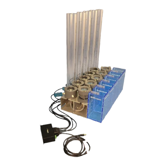
System Options Model PR16: Single Unit, Flow Cell: 5.0 cm ID, 5.0 cm Length Model PR16-5: Five Independent Units, Flow Cell: 5.0 cm OD, 5.0 cm Length Model PR16-81: Single Unit, Flow Cell: 8.0 cm ID, 5.0 cm Length Model PR16-85: Five Independent Units, Flow Cell: 8.0 cm ID, 5.0 cm Length Acquaint Yourself with the PR16 Components Major Components of the PR16 Setup. - Page 5 PR16 Flow Cell 1. Flow Cell Stud 2. Stud Wingnut 3. Flow Cell Cap 4. Perforated Plate 5. Mesh Screen 6. Cylinder O-ring 7. Sample Ring 8. Stud Nut 9. Stud Washer 10. Paper Filter Retainer 11. Flow Cell Base O-ring 12.
- Page 6 PR16 Parts 30. Reservoir O-ring 36. Female Luer Hose Connection 31. Stand Knob 37. Tubing 32. Knob Centralizer 38. Stopcock 33. Knob Spacer 39. Stand 34. Port Plug 40. Receiver 35. Male Luer hose Connection 41. Monitor™ Precision Pressure Transducer 42.
-
Page 7: Software Installation
Software Installation NOTE: The latest version of the Chameleon Software Application can always be downloaded for free from the SoilMoisture webpage below. https://www.soilmoisture.com/resources/Software-Downloads/ + Open the Windows Explorer, go to the USB drive and run “setup.exe” file. + Click “Next” in the “Monitor Transducer” window. - Page 8 + Click the “Browse” Button in the “Select Installation Folder” window to select the installation folder. We recommend the default folder “C:\SEC\Monitor\”. Click the “Disk Space” to see a list of your drives and space available on each of them. Select “Everyone”...
- Page 9 + Click “Close” in the “Installation Complete” window. A Windows Shortcut (Monitor Transducer) will be created on your computer Desktop. Assemble the Reservoir Assemble the Reservoir according to the schematic. Use a small amount of Vacuum Grease to lubricate the Air Tube and insert it in the central hole of the Stopper.
- Page 10 The Reservoir has 4 side ports. One of them can be used for refilling the Reservoir. This eliminates the need to remove the Stopper for refilling. You can connect the Reservoir to tap water, or to an elevated water reservoir (see the schematic). NOTE: the “elevated reservoir”...
- Page 11 Saturate the Soil Sample Connect a Stopcock to the Flow Cell Base and another Stopcock to the Reservoir Base. Then connect the Reservoir to the Flow Cell Base using the Tubing provided. Considering the vertical and horizontal distance of the Reservoir and the Flow Cell, cut the tubing to a length that is convenient and not too long.
- Page 12 bottom of the Cap should easily touch the Cylinder O-ring. Once the Cap is in place, put the Wingnuts over the Studs and secure them “half turn at a time”. This method is like securing the spare tire of a car. It ensures even progress among the Wingnuts.
- Page 13 Measurement Campaign: Constant Head Method Constant-Head Setup + Set up the system according to the schematic attached. + Connect the Monitor Transducer to your computer using the USB cable provided with the system. + Open the Monitor Transducer program. + Make sure that Valve B is open (schematic above). This is to expose the pressure sensor to ambient air. P.O.
- Page 14 + Open the Monitor Transducer from your Desktop. + If the Monitor sensor reads a pressure other than zero, go to “Monitor” menu then click “Zero”. The pressure reading should go to zero. + Once the sensor is zeroed, click on the “Measurement”...
- Page 15 5.13 cm. Please also note that the outside diameter of Air Tube is assumed to be 0.635 cm (you are not able to change it). + In the “Sample Diameter” field enter Sample Ring inside diameter (d). The inside diameter of PR16 ring is 5.0 cm. + In the “Sample Length” field enter sample length (L ).
- Page 16 + Make sure that the system is set up correctly. Valves A, B, C and D should be closed. + Open Valve D. + Open Valve A. + Wait until the Air Tube starts bubbling. + Wait for 5 more seconds for the system to stabilize. + Click the “Start”...
- Page 17 A step-like reading graph is an indication of a too short measurement time. + Once you get the first Average Flow Rate values, compare them with the measurement parameters table. If you need to readjust the head height or the measurement duration, do so and restart the measurement. For example, looking at the reading graph in image above (one-minute measurement time), you are still able to see some “step-like”...
- Page 18 + The Ksat value appears on the screen once the reading time is over (see the example screenshot above). NOTE: The first reading and the last reading (green highlight in the Readings Table) are used for measuring the Average Flow Rate and then Ksat. The software keeps reading until you press “Stop”.
- Page 19 P.O. Box 30025, Santa Barbara, CA 93130 U.S.A. | Phone: (805) 964-3525 | Fax: (805) 683-2189 Email: sales@soilmoisture.com | Website: http://www.soilmoisture.com...
- Page 20 Calculations Since the soil sample is already saturated at the beginning of the measurement, the Average Flow Rate at the end of measurement campaign can be considered as the steady flow rate (Q). At each time increment, the Average Flow Rate is calculated using the first reading, the last reading and the elapsed time between the two readings: Where Q is the steady-state flow rate (cm /min), V is the volume of water consumed (cm ), A...
- Page 21 The correction Factor (cf) converts the sensor reading (h) to the actual head height (H). In a standard PR16 setup (schematic above) cf is -4.5 cm (see the schematic above). P.O. Box 30025, Santa Barbara, CA 93130 U.S.A. | Phone: (805) 964-3525 | Fax: (805) 683-2189...
- Page 22 Performing a Measurement (Falling Head Method) + Setup the system according to the Falling-head setup schematic. NOTE: before filling up the Reservoir make sure that the Monitor Pressure Transducer is zeroed. +Initial Position: Valve C is open. Valve A is closed. Valve D is open.
- Page 23 + In the “Reservoir Diameter” field enter Reservoir inside diameter (D). The PR16 Reservoir ID is 5.13 cm. + In the “Sample Diameter” field enter the Sample Ring inside diameter (d). The inside diameter of the PR16 standard ring is 5.0 cm.
- Page 24 NOTE: cf is a negative number. Do not forget to enter it with a negative sign. + You need to also set the end point water level. Once the water level subsides below this level, the reading campaign ends automatically. Note that you need to enter the Actual Head Height, H (not the sensor reading, h). In the standard setup (the schematic above), 0.5 cm is a recommended end point.
- Page 25 + The K value appears on the screen once the overhead pressure drops below the designated endpoint level (2 cm in this example). A pop-up window prompts the end of the reading campaign. + Click “Save” to save the readings and the results in a CSV file. The file address can always be found at the top right corner of the measurement window.
- Page 26 Calculations The overhead pressure (water height) variation over time has an exponential trend: Where H is the overhead pressure at time t and a and b are coefficients of the exponential function. Saturated Hydraulic Conductivity then can be calculated as: Where K is saturated hydraulic conductivity, A is the Reservoir cross-sectional area, A...
- Page 27 A Constant Head Setup for the A Falling Head Setup for the Slow Soil Attachment (Sold separately). Fast Soil Attachment (Sold separately). A pipette reservoir is used to shorten the The Reservoir Body Pipe is placed directly over the measurement time. soil sample to maximize the water supply rate.
Need help?
Do you have a question about the PR16 and is the answer not in the manual?
Questions and answers