Table of Contents
Advertisement
Quick Links
Kelly KLS-8080N/NPS Sinusoidal BLDC/PMSM Controller User's Manual
Kelly KLS-8080N/NPS
Motor Controllers
User's Manual
Devices Supported:
KLS72501-8080N/NPS
KLS72601-8080N/NPS
KLS72701-8080N/NPS
KLS72801-8080N/NPS
KLS84501-8080N/NPS
KLS84601-8080N/NPS
KLS84701-8080N/NPS
KLS84801-8080N/NPS
KLS84101-8080N/NPS
KLS84121-8080N/NPS
KLS96401-8080N/NPS
KLS96501-8080N/NPS
KLS96601-8080N/NPS
KLS96701-8080N/NPS
KLS96901-8080N/NPS
KLS96111-8080N/NPS
KLS11401-8080N/NPS
KLS11501-8080N/NPS
KLS11601-8080N/NPS
KLS11701-8080N/NPS
KLS11901-8080N/NPS
KLS11111-8080N/NPS
KLS14351-8080N/NPS
KLS14401-8080N/NPS
KLS14451-8080N/NPS
KLS14601-8080N/NPS
KLS14751-8080N/NPS
KLS14901-8080N/NPS
KLS16601-8080N/NPS
KLS16751-8080N/NPS
V1.13
Rev.1.19
Sep. 2023
Advertisement
Table of Contents

Related Manuals for Kelly KLS11111-8080N


Summary of Contents for Kelly KLS11111-8080N
- Page 1 Kelly KLS-8080N/NPS Sinusoidal BLDC/PMSM Controller User’s Manual V1.13 Kelly KLS-8080N/NPS Motor Controllers User’s Manual Devices Supported: KLS72501-8080N/NPS KLS11401-8080N/NPS KLS72601-8080N/NPS KLS11501-8080N/NPS KLS72701-8080N/NPS KLS11601-8080N/NPS KLS72801-8080N/NPS KLS11701-8080N/NPS KLS84501-8080N/NPS KLS11901-8080N/NPS KLS84601-8080N/NPS KLS11111-8080N/NPS KLS84701-8080N/NPS KLS14351-8080N/NPS KLS84801-8080N/NPS KLS14401-8080N/NPS KLS84101-8080N/NPS KLS14451-8080N/NPS KLS84121-8080N/NPS KLS14601-8080N/NPS KLS96401-8080N/NPS KLS14751-8080N/NPS KLS96501-8080N/NPS KLS14901-8080N/NPS...
-
Page 2: Table Of Contents
Kelly KLS-8080N/NPS Sinusoidal BLDC/PMSM Controller User’s Manual V1.13 Contents Chapter 1 Introduction ................2 1.1 Overview........................ 2 Chapter 2 Features and Specifications ............3 2.1 General functions ....................3 2.2 Features ........................ 4 2.3 Specifications ......................5 2.4 Name Regulation ....................6 Chapter 3 Wiring and Installation ............... -
Page 3: Chapter 1 Introduction
Chapter 1 Introduction 1.1 Overview This manual introduces the Kelly sinusoidal wave brushless BLDC motor controllers‟ features, their installation and their maintenance. Read the manual carefully and thoroughly before using the controller. If you have any questions, please contact the support center of Kelly Controls. -
Page 4: Chapter 2 Features And Specifications
Kelly KLS-8080N/NPS Sinusoidal BLDC/PMSM Controller User’s Manual V1.13 And please don't try to connect the controller to user program while the motor is still running, let alone change the setting in user program or Android App. That is to say, if you want to connect controller to user program or try to do programming, please stop the motor first. -
Page 5: Features
Kelly KLS-8080N/NPS Sinusoidal BLDC/PMSM Controller User’s Manual V1.13 (16) Configurable motor over-temperature detection and protection with the recommended thermistor KTY84-130/150 or KTY83-122. (17) 3 hall position sensor inputs. Open collector, pull up provided. Sin/Cosin Speed sensors inputs. Can not support Resolver sensor type. -
Page 6: Specifications
Kelly KLS-8080N/NPS Sinusoidal BLDC/PMSM Controller User’s Manual V1.13 18) Current multiplication: Take less current from battery, output more current to motor. 19) Easy installation: 3-wire potentiometer will work. 20) Standard PC/Laptop computer to do programming. There is one more choice for customers to program KLS controller. -
Page 7: Name Regulation
2.4 Name Regulation The name regulation of Kelly KLS motor controllers KLS: Kelly BLDC motor controller based on sinusoidal waveform. KLS-8080N is supposed to work with brushless motor with three hall sensors while KLS-8080NPS can work with Sin/Cosin speed sensors. There are +5V, Sin, Cosin and GND I/O ports for brushless motor with Sin/Cosin speed sensors. - Page 8 Kelly KLS-8080N/NPS Sinusoidal BLDC/PMSM Controller User’s Manual V1.13 KLS96601-8080N/NPS 24-96 KLS96701-8080N/NPS 24-96 KLS96701-8080N/NPS 24-96 KLS96901-8080N/NPS 24-96 KLS96901-8080N/NPS 24-96 KLS96111-8080N/NPS 1100 24-96 KLS96111-8080N/NPS 1100 24-96 KLS11401-8080N/NPS 24-110 KLS11401-8080N/NPS 24-110 KLS11501-8080N/NPS 24-110 KLS11501-8080N/NPS 24-110 KLS11601-8080N/NPS 24-110 KLS11601-8080N/NPS 24-110 KLS11701-8080N/NPS 24-110 KLS11701-8080N/NPS 24-110...
-
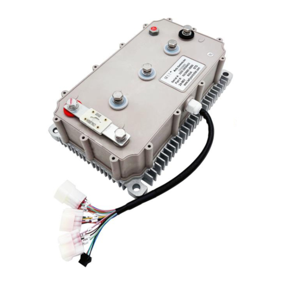
Page 9: Chapter 3 Wiring And Installation
Kelly KLS-8080N/NPS Sinusoidal BLDC/PMSM Controller User’s Manual V1.13 Chapter 3 Wiring and Installation 3.1 Mounting the Controller The controller can be oriented in any position which should be as clean and dry as possible, and if necessary, shielded with a cover to protect it from water and contaminants. - Page 10 Kelly KLS-8080N/NPS Sinusoidal BLDC/PMSM Controller User’s Manual V1.13 Figure 1: With Aluminum Heatsink at the bottom mounting holes‟ dimensions (dimensions in millimeters) +/B+/B-/U/V/W:M8...
- Page 11 Kelly KLS-8080N/NPS Sinusoidal BLDC/PMSM Controller User’s Manual V1.13 Figure 2: With Aluminum Liquid Cooling Heatsink at the bottom mounting holes‟ dimensions (dimensions in millimeters) +/B+/B-/U/V/W:M8...
- Page 12 Kelly KLS-8080N/NPS Sinusoidal BLDC/PMSM Controller User’s Manual V1.13 Figure3: With Sealed Aluminium Housing mounting holes‟ dimensions (dimensions in millimeters) +/B+/B-/U/V/W:M8...
- Page 13 Kelly KLS-8080N/NPS Sinusoidal BLDC/PMSM Controller User’s Manual V1.13 Figure4: With Sealed Aluminium Housing And Aluminum Liquid Cooling Heatsink at the bottom mounting holes‟ dimensions (dimensions in millimeters) +/B+/B-/U/V/W:M8...
-
Page 14: Connections
Kelly KLS-8080N/NPS Sinusoidal BLDC/PMSM Controller User’s Manual V1.13 3.2 Connections 3.2.1 Pin definition 1,The switch signal is valid to 12V on pin11. 2,12V capacity is low. This 12V only can be used for LED or switch signals. 3,Boost and Brake analog regeneration mode used the same pin as pin2. - Page 15 Kelly KLS-8080N/NPS Sinusoidal BLDC/PMSM Controller User’s Manual V1.13 DJ7091Y-2.3-11 Pin Definition (14) REV_SW: Reverse switch input. Orange (6) RTN: Signal return or power supply return. Black (12) FWD: Forward switch or High speed switch White (11) 12V:12V Source Red . Yellowish...
- Page 16 Kelly KLS-8080N/NPS Sinusoidal BLDC/PMSM Controller User’s Manual V1.13 3.2.2 Standard Wiring Figure 5: KLS-8080N controller standard wiring...
- Page 17 Kelly KLS-8080N/NPS Sinusoidal BLDC/PMSM Controller User’s Manual V1.13 Figure 6: KLS8080NPS controller standard wiring...
- Page 18 Kelly KLS-8080N/NPS Sinusoidal BLDC/PMSM Controller User’s Manual V1.13 3.2.3 Optional wiring of KLS-8080N/NPS controller The 12V input signal of the pin supplies the second braking function of the controller. Figure 7: Wiring of brake switch(12V): 12V is provided by external source.
-
Page 19: Installation Check List
Kelly KLS-8080N/NPS Sinusoidal BLDC/PMSM Controller User’s Manual V1.13 3.2.4 Communication Port A 4pin connector to RS232 port is provided to communicate with host computer for calibration and configuration. Figure 10: RS232 Interface on 4pin connector to RS232 converter Figure 11:SM-4P connector for communication interface on KLS8080N controller 3.3 Installation Check List... -
Page 20: Chapter 4 Programmable Parameters
Kelly KLS-8080N/NPS Sinusoidal BLDC/PMSM Controller User’s Manual V1.13 • Make sure the wire is connected correctly • Turn the PWR switch on. • The fault code will be detected automatically at restart. • With the brake switch open, select a direction and operate the throttle. The motor should spin in the selected direction. -
Page 21: Step 1
Kelly KLS-8080N/NPS Sinusoidal BLDC/PMSM Controller User’s Manual V1.13 4.1 Step 1 (1)Low Volt: The min voltage of reporting this fault - Range 18~173, depending on model. Controller will not operate when battery voltage is near the value so as to protect battery. - Page 22 (7)TPS High Err: Hall active pedal, if higher than the value, report the fault of TPS Type. Range: 80~100 As you may know, the output of hall throttle from Kelly is about from 0.86V to 4.2V. Our controller will report 3.3 error code if the output of hall throttle is below 0.5V or above 4.5V by default.
- Page 23 Kelly KLS-8080N/NPS Sinusoidal BLDC/PMSM Controller User’s Manual V1.13 (12)Brake sensor Dead Low: Brake sensor Dead Zone Low. Range: 5~40 Functional description: Set throttle effective starting point Suggestion: Set according to the practical situation, factory default is 20%*5V=1.0V. (13)Brake sensor Dead High: Brake sensor Dead Zone High. Range: 60~95 Functional description: Set throttle effective ending point Suggestion: Set according to the practical situation, factory default is 80%*5V=4.0V.
- Page 24 Kelly KLS-8080N/NPS Sinusoidal BLDC/PMSM Controller User’s Manual V1.13 Value range: Enable and Disable Functional description: If enabled, the controller will detect the current pedal status at power up. If throttle got effective output, the controller will report fault and not operate.
- Page 25 Kelly KLS-8080N/NPS Sinusoidal BLDC/PMSM Controller User’s Manual V1.13 (20-B)Foot Switch Value range: Enable and Disable Functional description: If enabled, the foot switch will be activated. The controller will not accept the throttle signal if the foot switch is turned off. Please see figure 4.1.
-
Page 26: Step 2
Kelly KLS-8080N/NPS Sinusoidal BLDC/PMSM Controller User’s Manual V1.13 control quit. Suggestion: factory default is Disable. (27)Anti-Slip: If enabled, the controller will try to prevent the vehicle rolling back on downhill faster and faster. If the ratio of gearbox is high, it can try to help the motor stop on the downhill. But usually this function only helps motor stop rolling back too fast. -
Page 27: Step 3
Kelly KLS-8080N/NPS Sinusoidal BLDC/PMSM Controller User’s Manual V1.13 High Temp Cut Out °C: Motor High Temp Cut Out, nominal value 130°C. Range: 60~170 Resume °C: Motor High Temp Resume Temp, nominal value 110°C. The controller will resume work when the motor temp is at 110 degrees inside. Range: 60~170 (6)Line Hall Zero: It is only useful when the speed sensor is at 4. - Page 28 Kelly KLS-8080N/NPS Sinusoidal BLDC/PMSM Controller User’s Manual V1.13 Factory set is 0 (3)Accel Time: Accel Time, the time of TPS Torque from 0 to max, accuracy 0.1s, 5 is equal to 0.5s. Range: 1~250 Factory set is 10 (4)Accel Rls Time: Accel Release Time, the time of TPS Torque from max to 0, accuracy 0.1s.
-
Page 29: How To Use Identification Angle Operation For Kls-8080N Controller
Kelly KLS-8080N/NPS Sinusoidal BLDC/PMSM Controller User’s Manual V1.13 (11) Compensation Per% Tried to increase the current usage during Anti-Slip operation. (12)IVT BRK MAX and IVT BRK MIN: These two items are only useful when Joystick function is enabled in the user program. When you want to use Change Dir Brake to reduce the delay time... - Page 30 Kelly KLS-8080N/NPS Sinusoidal BLDC/PMSM Controller User’s Manual V1.13 2, Please connect the controller to user program by using an USB to RS232 cable and SM-4A DB9(RS232) Converter.
- Page 31 Kelly KLS-8080N/NPS Sinusoidal BLDC/PMSM Controller User’s Manual V1.13 Customers also can use a Z-TEK USB to RS232 cable and SM-4A DB9(RS232) Converter to connect the controller to an Android Tablet. The third option is customers can buy our Bluetooth converter to connect the controller to Android Phone.
- Page 32 Kelly KLS-8080N/NPS Sinusoidal BLDC/PMSM Controller User’s Manual V1.13 Please check whether the Identification Angle item is at 85 or not. It is correct if identification angle item is at 85. 5,Please fill 170 in the identification angle item. And please click the write button. The user program will give a pop-up window which show the Write operation is successful.
- Page 33 Kelly KLS-8080N/NPS Sinusoidal BLDC/PMSM Controller User’s Manual V1.13 11,As long as it is not reset error code, the value in identification angle will not go back to 85.The value is always at 170.That is to say, the controller is still in the processing of identification operation.
-
Page 34: How To Use Identification Angle Operation For Kls-8080Nps Controller
Kelly KLS-8080N/NPS Sinusoidal BLDC/PMSM Controller User’s Manual V1.13 4.5 How to use Identification angle operation for KLS-8080NPS controller We must do Identification angle operation before running motor for all KLS controllers. The Identification angle operation can be done in PC program or Android App(Tablet or Cell Phone). - Page 35 Kelly KLS-8080N/NPS Sinusoidal BLDC/PMSM Controller User’s Manual V1.13 DB9(RS232) Converter. Customers also can use a Z-TEK USB to RS232 cable and SM-4A DB9(RS232) Converter to connect the controller to an Android Tablet. The third option is customers can buy our Bluetooth converter to connect the controller to Android Phone.
- Page 36 Kelly KLS-8080N/NPS Sinusoidal BLDC/PMSM Controller User’s Manual V1.13 3,Please download the controller user program from our website for free. www.kellycontroller.com/support.php Please install the user program in your computer, Tablet or Phone. 4.1,Please turn on the key switch so that the controller can get power supply from B+/B- and Pin7/Pin6.Please try to open the user program in your computer or other devices.
- Page 37 Kelly KLS-8080N/NPS Sinusoidal BLDC/PMSM Controller User’s Manual V1.13 Usually we just need to configure two parameters in user program according to the specification of Sin/Cosin speed sensor. Please click Motor button in the user program. Line hall zero: The line hall zero point is at 3Vdd/5=3*5V/5=3.0V.So we need to fill 3*1023/5=613.8=614 for Line hall zero parameter instead of 508 in the user program.
- Page 38 Kelly KLS-8080N/NPS Sinusoidal BLDC/PMSM Controller User’s Manual V1.13 So output range of Sin/Cosin speed sensor is 3-1.1V=1.9V to 3+1.1V=4.1V.(1.9V-4.1V). We set the Line hall high err at 972.It is about 4.75V.The line hall low err at 50.It is about 0.25V.
- Page 39 Kelly KLS-8080N/NPS Sinusoidal BLDC/PMSM Controller User’s Manual V1.13 see any error codes. 13,If the constant beep sound lasts above 5 minters and there are other error codes such as Identify error, hall err etc, please return to the first picture of user program. Please write 85 instead in identification angle by manual.
-
Page 40: Chapter 5 Maintenance
Identification angle operation. • Use a straight through RS232 cable or USB converter provided by Kelly to connect to a host computer. Provide >+18V to PWR(for a 24V controller, provide >+8V). Wire power supply return(supply negative) to any RTN pin. -
Page 41: Buzzer Error Codes
Kelly KLS-8080N/NPS Sinusoidal BLDC/PMSM Controller User’s Manual V1.13 Caution: •Make certain that the motor is connected before trying to run Identification angle The controller needs to be connected to function in the configuration software. batteries, motor and throttle before Identification operation. That is to say, it is not enough to connect only power supply(PWR=pin7) to batteries for Identification Angle operation. - Page 42 Kelly KLS-8080N/NPS Sinusoidal BLDC/PMSM Controller User’s Manual V1.13 caused by too low a value of Regen or throttle potentiometers or incorrect wiring. 3. Controller is damaged. Contact Kelly about a warranty repair. Over temperature ¤¤ ¤¤¤ The controller temperature has exceeded 100℃. The controller will be stopped but will restart when temperature falls below 80℃.
-
Page 43: Contact Us
Kelly KLS-8080N/NPS Sinusoidal BLDC/PMSM Controller User’s Manual V1.13 Contact Us: Kelly Controls Home Page: http://www.KellyController.com Download user manual,instructions and user program: www.kellycontroller.com/support.php E-mail: Sales@Kelly-Controls.com Phone: (01) 224 637 5092...
Need help?
Do you have a question about the KLS11111-8080N and is the answer not in the manual?
Questions and answers