Table of Contents
Advertisement
Quick Links
Advertisement
Table of Contents

Related Manuals for Growatt SPF 18KT DVM-MPV


Summary of Contents for Growatt SPF 18KT DVM-MPV
- Page 1 User Manual Off Grid Solar Inverter Split Phase 18KW Version: 1.0...
-
Page 2: Table Of Contents
Table Of Contents Information on this Manual ..........................1 Validity ................................1 Scope ................................1 Target Group ..............................1 Safety Instructions ............................1 Introduction ..............................2 Features ................................2 Product Overview .............................. 3 Installation ..............................4 Unpacking and Inspection ..........................4 Preparation ............................... -
Page 3: Information On This Manual
Information on this Manual Validity This manual is valid for the following devices: Off gird solar inverter with MPPT controller, 18KW; Scope This manual describes the assembly, installation, operation and troubleshooting of this unit. Please read this manual carefully before installations and operations. Target Group This document is intended for qualified persons and end users. -
Page 4: Introduction
Introduction Hybrid Power System This is a multifunctional split-phase output off grid solar inverter, integrated with a MPPT solar charge controller, a low frequency pure sine wave inverter and a UPS function module in one machine, which is perfect for off grid backup power and self-consumption applications. The whole system also need other devices to achieve complete running such as PV modules, generator, or utility grid. -
Page 5: Product Overview
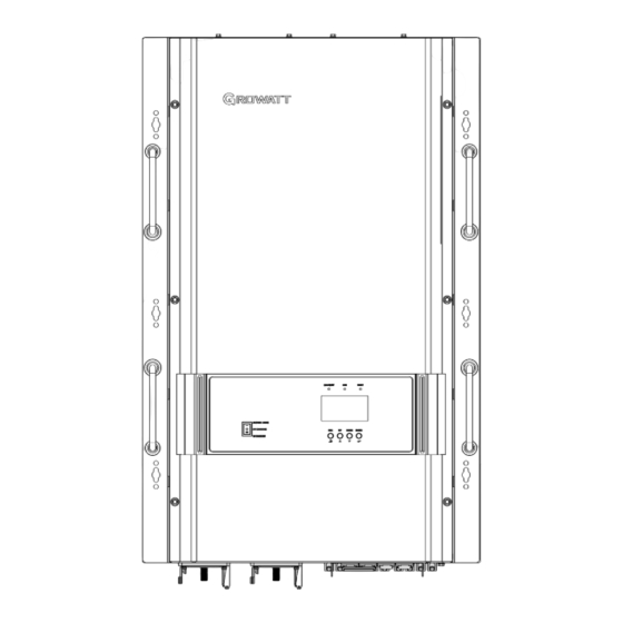
Product Overview 1. ON/OFF Power Switch 2. LCD Display 3. Status Indicator 4. Charging Indicator 5. Fault Indicator 6. Function Buttons 7. Negative Battery Terminal 8. Positive Battery Terminal 9. DC Fan 10. Dry Contact For AGS 11. USB Port 12. -
Page 6: Installation
Installation Unpacking and Inspection Before installation, please inspect the unit. Be sure that nothing inside the package is damaged. You should have received the following items in the package: The unit x1 User manual x 1 Communication cable x 1 Preparation Before connecting all wiring, please take off bottom cover by removing four screws as shown below. -
Page 7: Battery Connection
Battery Connection CAUTION: For safety operation and regulation compliance, it’s requested to install a separate DC over-current protector or disconnect device between battery and inverter. It may not be requested to have a disconnect device in some applications, however, it’s still requested to have over-current protection installed. Please refer to typical amperage in below table as required fuse or breaker size. - Page 8 Lithium battery connection If need to communicate with lithium battery BMS, the inverter protocol should have matched the BMS first. There’re two connectors on the lithium battery, RJ45 port of BMS and power cable. Please follow below steps to implement lithium battery connection: 1.
- Page 9 2. LCD setting To connect battery BMS, need to set the battery type as “LI” in Program 05. After set “LI” in Program 05, it will switch to Program 91 to choose communication protocol. You can choose RS485 c ommunication protocol which is from L01 to L50, and you can also choose CAN communication protocol which is from L51 to L99.
-
Page 10: Ac Input/Output Connection
Note:When the battery type set to Li, the setting option 12, 13, 21 will change to display percent. Note: When the battery type set as“LI”, the Maximum charge current can't be modified by the user. When the communication fail, the inverter will cut off output. Note: Any questions about communicating with BMS, please consult with the supplier. - Page 11 120Vac output Input: HOT1+ HOT2+Ground Output: HOT1+ N or HOT2+ N Please follow below steps to implement AC input/output connection: 1. Before making AC input/output connection, be sure to open DC protector or disconnector first. 2. Remove insulation sleeve 10mm for six conductors. And shorten phase L and neutral conductor N 3 mm. 3.
-
Page 13: Pv Connection
PV Connection CAUTION: Before connecting to PV modules, please install separately a DC circuit breaker between inverter and PV modules. WARNING! All wiring must be performed by a qualified personnel. WARNING! It'’ very important for system safety and efficient operation to use appropriate cable for PV module connection. -
Page 14: Dry Contact Signal
Dry Contact Signal There is one dry contact (3A/250VAC) available on the rear panel. It could be used to deliver signal to generator when battery voltage reaches warning level. 1. The wiring between generator and the inverter (not all generators are the same wiring diagram as below, please ask supplier for instruction if there’s any questions.) Dry contact port: Unit Status... - Page 15 to 100A in small increments on the inverter’s LCD. This is helpful if this powerful charger applies charging to a small capacity battery bank. There are mainly 3 stages: Bulk Charging: This is the initial stage of charging. While Bulk Charging, the charger supplies the battery with controlled constant current.
- Page 16 Battery Equalization Equalization function is added into charge controller. It reverses the buildup of negative chemical effects like stratification, a condition where acid concentration is greater at the bottom of the battery than at the top. Equalizationalso helps to remove sulfate crystals that might have built up on the plates. If left unchecked, this condition, called sulfation, will reduce the overall capacity of the battery.
- Page 17 Power Saver The “Power Saver” function is dedicated to conserve battery power when AC power demand is either minimal or not required at all by the loads. In this mode, the inverter pulses the AC output looking for an AC load (i.e., electrical appliance). Whenever an AC load (greater than 500 watts at 120Vac) is turned on, the inverter recognizes the need for power and automatically starts inverting and output goes to full voltage.
-
Page 18: Operation
Operation Power ON/OFF Once the unit has been properly installed and the batteries are connected well, simply press On/Off switch (located on the button of the case) to turn on the unit. Operation and Display Panel The operation and display panel, shown in below chart, is on the front panel of the inverter. It includes three indicators, four function keys and a LCD display, indicating the operating status and input/output power information. -
Page 19: Lcd Display Icons
LCD Display Icons Icon Description ACInput Information AC input icon Indicate AC input power, AC input voltage, AC input frequency, AC input current Indicate AC power loads in bypass PVInput Information PV input icon Indicate PV power, PV voltage, PV current Output Information Inverter icon Indicate output voltage, output current, output frequency, inverter... -
Page 20: Lcd Setting
In AC mode, battery icon will present Battery Charging Status Status Battery voltage LCD Display <2V/cell 4 bars will flash in turns. Bottom bar will be on and the other three bars Constant Current 2 ~ 2.083V/cell will flash in turns. mode / Constant Bottom two bars will be on and the other two bars 2.083 ~ 2.167V/cell... - Page 21 Setting Programs: Program Description Setting Option Solar first Solar energy provides power to the loads as first priority. If solar energy is not sufficient to power all connected loads, battery energy will supply power the loads at the same time. Utility provides power to the loads only when any one condition happens: - Solar energy is notavailable...
- Page 22 AGM (Default) Flood User-Defined If “User-Defined” is selected, battery charge voltage and low DC cut- off voltage can be set up in program 19, 20 and 21. User-Defined 2 Battery type (Suitable for lithium battery when no communicating with BMS) If “User-Defined 2”...
- Page 23 50Hz (default) Output frequency 60Hz Maximum utility charging current Note: If setting value in Program 02 is smaller than that in Program 11, Default 30A, 0A~100A Settable the inverter will apply (If LI is selected in Program 5, this program can’t be set up) charging current from Program 02 for utility charger...
- Page 24 Only Solar Solar energy will be the only charger source no matter utility is available or not. If this off grid solar inverter is working in Battery mode or Power saving mode, only solar energy can charge battery. Solar energy will charge battery if it's available and sufficient.
- Page 25 battery at the same time. RS485 communication address Default 001,001-255 settable Battery equalization disable Battery equalization Battery equalization enable (default) If “Flooded” or “User-Defined” is selected in program 05, this program can be set up. Battery equalization voltage 48V model: Default 58.4V, 48.0V~60V Settable (the value should be higher than Program 19 value) Battery equalized time Default 60min, 5min~900min Settable...
-
Page 26: Display Information
Display Information The LCD display information will be switched in turns by pressing “UP” or “DOWN” key. The selectable information is switched as below order: voltage, frequency, current, power, firmware version. Setting Information LCD display ① AC Input voltage (If it flashes, it indicates that the input voltage of the generator is displayed at this time, and the current, power and frequency... - Page 27 ① AC input power in Watts ② Inverter temperature ③ Load power in Watts ④ Left:PV1 input power in Watts Right:PV2 input power in Watts ⑤ Battery percentage ⑥ Warning or Fault code Firmware version (CPU1: 040-00-b21; CPU2:041-00- b21) ①Model type (SIG: ②Output...
-
Page 28: Operating Mode Description
Operating Mode Description Description LCD display Operation mode When utility grid connected, no charging; Standby mode /Power PV can charge saving mode Note: No output is supplied by PV *Standby mode: The still can charge batteries. inverter is not turned on yet but at this time, the inverter can charge battery without AC output. -
Page 29: Fault Reference Code
Fault Reference Code Fault Code Fault Event Icon on Inverter Over temperature Battery voltage is too high Battery voltage is too low Output short circuited Output voltage is abnormal. Output voltage is too high. Overload time out BMS communication error Over current or surge MOS over current Warning Indicator... -
Page 30: Trouble Shooting
Trouble Shooting Problem LCD/LED/Buzzer Explanation / Possible cause What to do Unit shuts down LCD/LEDs and buzzer automatically will be active for 3 The battery voltage is too low 1. Re-charge battery. during startup seconds and then (<1.91V/Cell) 2. Replace battery. process. -
Page 31: Specifications
Specifications MODEL SPF 18KT DVM-MPV Battery voltage 48VDC INVERTER OUTPUT Rated Power 18KW Surge Rating (20ms) 43KW Pure sine wave/ same as input (bypass mode) Waveform Nominal Output Voltage 104V-110V-115V-120Vac / 208V-220V-230V-240Vac(+/-10% RMS) Output Frequency 50Hz/60Hz(+/-0.3 Hz) Inverter Efficiency(Peak) >85% Line Mode Efficiency >95%...
Need help?
Do you have a question about the SPF 18KT DVM-MPV and is the answer not in the manual?
Questions and answers